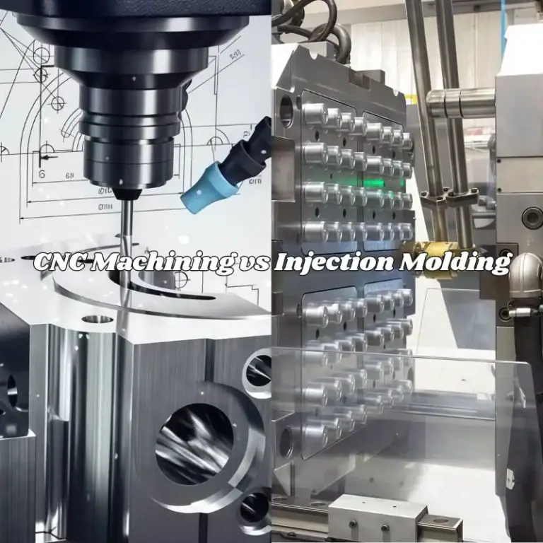
PCB testing equipment involves multiple operations. Part design affects not only whether the equipment can be assembled smoothly, but also the positioning of the PCB during testing. CNC machining can produce non-standard parts such as mounting plates, test fixtures, support bases, and positioning components according to equipment drawings. It is suitable for prototype development, engineering trials, and subsequent production. For this type of electronic testing equipment, the manufacturing plan also needs to address practical requirements such as ESD, material selection, machining deformation, and surface treatment in advance.
Which Parts of PCB Testing Equipment Are Suitable for CNC Machining?
PCB testing equipment contains many non-standard structural parts and precision functional components. Different parts have different requirements for machining accuracy, material properties, and surface quality. Proper classification helps control machining costs.
Testing Platforms and Mounting Structural Parts
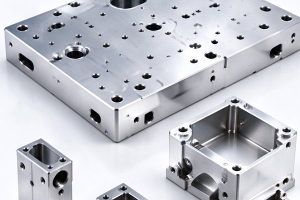
Equipment base plates, mounting plates, support bases, and other components provide module fixation and positioning. The key is to maintain the positional relationship between reference surfaces and mounting holes.
- Equipment Base Plates: Check flatness, hole positions, and machining datums to prevent displacement after assembly.
- Sensor Mounting Bases: Control mounting hole positions and mounting surface dimensions to facilitate repeatable sensor positioning.
- Support Brackets and Connecting Plates: Machine steps, slots, and connection holes according to the equipment layout to meet module assembly requirements.
After machining, these structural parts can provide a reliable mounting foundation for testing modules and auxiliary mechanisms.
PCB Positioning and Testing Fixtures
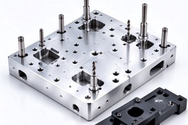
PCB testing usually requires repeated placement of circuit boards. Features such as locating pin holes, limit slots, and pressing areas directly affect the testing position. Static control during fixture-to-PCB contact also needs to be considered.
- Positioning Fixtures: Machine positioning slots, pin holes, and limiting structures according to the PCB outline to control repeatability.
- Testing Fixtures: Reserve mounting positions for probes, connectors, or test interfaces and properly plan the contact areas.
- ESD-Controlled Structural Parts: Positioning blocks, support pads, guide components, and other parts that directly contact PCBs or PCBAs should use static-dissipative materials according to ESD requirements, reducing the risk of discharge caused by static charge accumulation in ordinary insulating materials.
These parts need to be customized around PCB dimensions, testing procedures, and ESD control requirements to balance positioning accuracy with electronic component protection.
How Can CNC Machining Accuracy Be Controlled for PCB Testing Equipment?
Parts for testing equipment are not simply about achieving a single dimensional accuracy. Hole positions, datums, flatness, and assembly relationships between multiple parts must also be controlled, while inspection standards should be determined according to actual functions.
Conduct a DFM Review Before Machining
Before formal machining, manufacturing challenges should be analyzed based on the 3D model, engineering drawings, and assembly relationships.
- Check Tool Accessibility: Confirm that deep slots, narrow slots, deep cavities, and other features can be machined properly.
- Define Machining Datums: Determine the primary positioning surfaces and machining datums according to equipment assembly requirements.
- Optimize Fixturing Plans: Reduce unnecessary re-fixturing and minimize errors caused by repeated positioning.
Addressing manufacturing feasibility issues in advance can reduce rework and design modifications during the prototype stage.
Arrange Inspection for Critical Features
Hole positions, planes, and positioning structures in PCB testing equipment often directly affect equipment operation, so appropriate inspection methods should be arranged according to drawing requirements. Calipers and micrometers can be used for suitable linear dimension checks, while flatness, perpendicularity, position, and complex geometric relationships can be verified with height gauges, vision measuring systems, or CMMs according to the required accuracy. The actual inspection method should be selected based on tolerance levels and part structures rather than using the same inspection equipment for every dimension.
Control Machining Deformation of Thin-Wall and Large Parts
Large mounting plates and thin-wall brackets in PCB testing equipment may experience stress release and dimensional changes after substantial material removal. The machining sequence should therefore be planned in advance.
- Leave Stock During Rough Machining: Avoid removing excessive material in a single operation.
- Arrange Rough and Finish Machining Properly: Complete critical dimensions during a relatively stable machining stage.
- Check the Free State After Machining: For high-precision mounting parts, pay attention to changes in flatness after the part is released from the fixture.
Including deformation control in the machining plan can improve the fit of large mounting components during actual assembly.
How Can CNC Machining for PCB Testing Equipment Balance Lead Time and Cost?
When purchasing parts for testing equipment, customers usually care about prototype speed as well as later modifications, batch delivery, material selection, and overall machining costs.
Select the Machining Plan According to Quantity
Different order quantities require different levels of process preparation, and production investment can be increased gradually according to the project stage.
| Project Stage | Main Requirement | CNC Machining Focus | Customer Concerns |
| Design Validation | Rapid prototype production | Fast programming and single-piece machining | Lead time, dimensions, assembly |
| Engineering Trial | Validate equipment structure | Optimized fixturing and machining processes | Accuracy, modification response |
| Pilot Production | Validate repeat production | Standardized programs and inspection procedures | Consistency, cost |
| Mass Production | Stable continuous supply | Standardized machining and process control | Lead time, yield, batch stability |
| Design Change | Rapid part adjustment | Program and process document modification | Response speed, rework risk |
Adjusting the machining approach according to the project stage can avoid excessive production preparation during prototyping while allowing mature parts to transition more smoothly into batch manufacturing.
Material Selection Should Match Testing Equipment Conditions
Common structural materials for PCB testing equipment include aluminum alloys, stainless steel, and engineering plastics. Aluminum alloys are relatively lightweight and suitable for base plates, mounting plates, and certain fixtures. Hard anodizing and other wear-resistant treatments can be considered when friction and wear are present. When ESD engineering plastics are used for positioning blocks, support pads, guide components, and other parts that directly contact PCBs or PCBAs, static-dissipative materials such as ESD-POM should be prioritized according to ESD requirements rather than selecting materials based only on insulation, wear resistance, or low-friction properties. Material selection should consider part function, dimensional stability, friction conditions, ESD requirements, and the operating environment.
Surface Treatment Should Match Conductivity and Wear Requirements
Aluminum alloy parts in PCB testing equipment do not all require the same surface treatment. The process should be determined according to actual contact conditions and electrical requirements.
- Wear-Resistant Areas: Positioning blocks, sliding structures, and repeatedly contacted areas can be considered for hard anodizing according to load, friction, and fit requirements to improve surface wear resistance.
- Conductive and Grounding Areas: Ordinary anodized layers are electrically insulating. If a part needs to maintain a conductive or grounding path, a surface treatment suitable for conductivity should be selected, or designated contact areas should be masked to preserve the necessary conductive surfaces.
- Dimensional Fit Areas: For precision-fit parts, appropriate machining allowance should be reserved before surface treatment, and coating thickness should be included in dimensional control.
Surface treatment should be planned together with the part’s wear, electrical, and assembly requirements.
What Capabilities Should a CNC Supplier for PCB Testing Equipment Have?
PCB testing equipment parts often involve multiple varieties, small batches, and frequent modifications. A supplier needs to provide coordinated capabilities from drawing interpretation through machining and inspection.
Ability to Handle Complex Hole Patterns and Multi-Surface Structures
Testing equipment parts often contain mounting holes, positioning holes, steps, slots, and machining features in different directions.
- Multi-Axis Machining Capability: Depending on the structure, complex parts can be processed using 3-axis, 4-axis, or 5-axis CNC machining.
- Precision Hole Position Control: Focus on maintaining the positional relationship between positioning holes, pin holes, and mounting holes.
- Multi-Surface Machining Planning: Proper fixturing can reduce the effect of repeated positioning on accuracy.
The stronger the capability for complex structural machining, the easier it is to handle customized requirements for non-standard testing equipment.
Quality Control Capability from Prototypes to Batch Production
PCB testing equipment parts need to maintain consistent dimensions and assembly relationships at different production stages. Suppliers should establish a complete process inspection system. During the confirmation stage, key dimensions are checked against drawing requirements after machining. During process inspection, necessary process controls are applied to critical dimensions and high-risk features. During final inspection, dimensions, appearance, and relevant quality records are completed according to order requirements. A complete inspection process can reduce dimensional variation during batch production and provide customers with more stable subsequent assembly.
The manufacturing challenges of PCB testing equipment are often concentrated in non-standard structures, fixture contact areas, and electronic component protection requirements. Actual projects also need to determine part solutions according to PCB specifications, testing methods, and equipment movements. Through drawing review and machining planning, structural and manufacturing issues can be identified earlier, leaving room for adjustment during subsequent equipment assembly and project implementation.