CNC turning is widely used in precision machinery, automotive components, automation equipment, electronics, and industrial fittings. For businesses that require custom shafts, metal sleeves, threaded connectors, and precision rotating components, surface roughness affects friction, fit accuracy, sealing performance, and service life. Even when a part meets the dimensional requirements specified in an engineering drawing, visible tool marks, burrs, or localized scratches can still affect assembly and equipment operation. Selecting suitable cutting tools, optimizing machining parameters, controlling workpiece vibration, and implementing reliable inspection procedures can improve CNC turning surface finish, reduce rework and scrap, and enhance manufacturing consistency.
Factors Affecting CNC Turning Surface Roughness
CNC turning surface roughness is commonly evaluated using parameters such as Ra and Rz. Ra represents the arithmetic average of the absolute profile deviations and is frequently specified on engineering drawings. Different components require different surface finishes. General structural parts may prioritize machining efficiency, while bearing fits, sealing surfaces, and sliding contact surfaces may require stricter surface quality control. Understanding the main factors affecting roughness helps manufacturers develop more effective machining processes.
Cutting Speed and Feed Rate
Cutting speed and feed rate directly influence cutting conditions, tool wear, and surface texture. A higher feed rate generally produces more noticeable geometric tool marks, while reducing the feed rate can improve theoretical surface roughness, although machining time may increase. Cutting speed affects cutting temperature, built-up edge formation, and tool wear, and different materials respond differently to changes in speed.
- Adjust the feed rate appropriately: For precision shafts, sleeves, and connectors requiring a high-quality surface finish, the finishing feed rate can be reduced when production requirements allow. Adjustments should also consider the tool nose radius, material properties, and tool condition to prevent unstable surface quality caused by unsuitable settings.
- Select an appropriate cutting speed: For materials with good machinability, such as aluminum alloys, cutting speeds can be selected according to tool recommendations and machine capabilities. When machining certain stainless steel grades, particular attention should be paid to cutting heat and work hardening to prevent abnormal tool wear and surface defects caused by unsuitable speeds.
- Control the depth of cut: Finishing operations generally use an appropriate depth of cut to maintain stable cutting conditions. If the allowance is too small, the tool may rub or deform the material instead of cutting it effectively. An excessive allowance can increase cutting loads and cause vibration or dimensional variation.
- Validate parameter combinations: Cutting speed, feed rate, depth of cut, and tool geometry are interrelated. Instead of adjusting only one parameter, manufacturers should verify the combination through trial machining to balance surface roughness, cycle time, and tool life.
For batch CNC turning orders, record the cutting parameters and surface inspection results during first-article production. Applying verified processes to subsequent parts and making adjustments based on tool wear can reduce surface quality variations between batches.
Cutting Tool Material and Nose Geometry
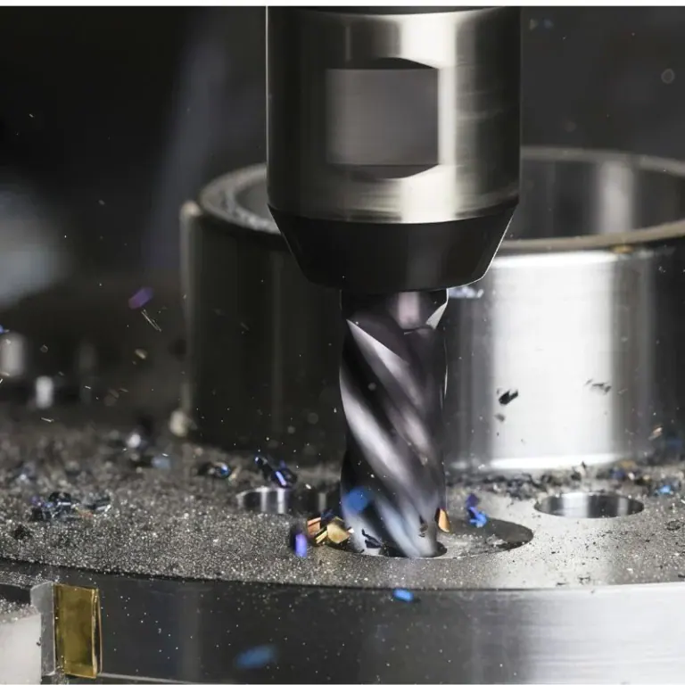
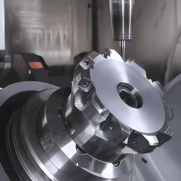
Tool material, cutting-edge sharpness, nose radius, and chip-breaker design all influence the machined surface. Excessive tool wear can cause dragging marks, scratches, or material tearing. An unsuitable relationship between tool geometry and feed rate can also create noticeable periodic tool marks. Tool selection should therefore reflect the workpiece material, part geometry, and required surface roughness.
- Choose suitable tool materials: When machining aluminum alloys, tool sharpness and built-up edge control are important. For stainless steel, wear resistance, toughness, and heat resistance must be considered together. Difficult-to-machine materials such as titanium alloys also require evaluation of tool stability under high temperatures and cutting loads.
- Select an appropriate tool nose radius: Under suitable conditions, a larger tool nose radius can improve theoretical surface roughness. However, it may also increase radial cutting forces, making slender shafts and thin-wall components more susceptible to vibration. The final selection should account for workpiece rigidity, feed rate, and machine stability.
- Replace worn tools promptly: As cutting tools are used, their edges gradually wear and become less sharp, potentially increasing cutting forces and reducing surface quality. Maintaining tool-life records, monitoring changes in the machined surface, and replacing tools when they reach established limits can reduce the risk of roughness defects in batch production.
- Check tool installation: Incorrect tool height, excessive tool overhang, and inadequate clamping can affect cutting stability. Minimizing unnecessary overhang and ensuring secure tool installation help reduce vibration and irregular surface patterns.
For high-precision CNC-turned parts, tool management should be incorporated into standardized production procedures. Consistent tool specifications, service-life records, and regular tool inspections can improve repeatability and minimize surface quality variations caused by differences in tool condition.
Workpiece Rigidity and Machine Stability
Even with suitable cutting parameters, unstable workholding, poor machine condition, or excessive vibration can prevent manufacturers from achieving a uniform surface finish. Slender shafts, thin-wall sleeves, and small-diameter components are particularly sensitive to cutting forces and may develop chatter marks, localized waviness, or dimensional changes.
Workholding should be planned according to part diameter, length, wall thickness, and machining position. Slender shafts may require a tailstock or another suitable support method. Thin-wall sleeves require carefully controlled clamping forces to prevent deformation. Chuck jaws, soft jaws, and locating surfaces should also remain clean so that chips and debris do not affect positioning accuracy.
Machine spindle condition, guideway wear, turret rigidity, and maintenance quality can also influence machining results. Regular inspections of spindle operation, fixture accuracy, and critical machine components help identify sources of vibration. If regular waviness appears on the surface, inspect the machine, tool, workholding arrangement, and cutting parameters instead of relying only on reducing the feed rate.
Methods to Improve CNC Turning Surface Finish
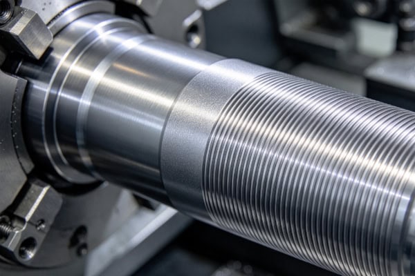
Improving CNC turning surface finish requires coordinated process planning, cutting parameter optimization, coolant management, and operation sequencing. Different materials and component geometries require different machining strategies. An effective finishing process should meet drawing specifications while minimizing vibration, thermal deformation, and tool wear.
Optimize Roughing and Finishing Operations
Roughing and finishing serve different manufacturing purposes. Roughing removes excess material efficiently, while finishing achieves the final dimensions and surface quality. If machining allowances are poorly allocated or the workpiece remains vulnerable to deformation before finishing, surface roughness may become inconsistent.
- Maintain an appropriate finishing allowance: During roughing, leave a suitable amount of material based on the workpiece material, dimensions, and subsequent operations. Excessive allowance increases the finishing load, while insufficient allowance may prevent stable cutting and compromise surface quality and dimensional control.
- Plan the machining sequence: For turned parts with steps, grooves, internal holes, and threads, arrange operations according to the component geometry. Surfaces requiring concentricity or precise fits should be machined under stable positioning conditions to minimize errors caused by repeated setups.
- Control finishing loads: During finishing, maintain continuous and stable cutting conditions. Avoid frequent tool entry and exit or large variations in cutting load caused by uneven allowances. For slender shafts and thin-wall components, optimize support and machining sequences to reduce deformation.
- Avoid unnecessary secondary operations: If appropriate tooling and optimized cutting parameters can achieve the specified surface roughness, additional polishing or finishing operations may be unnecessary. When the part’s function requires a finer finish, select a suitable finishing or post-processing method according to the drawing requirements.
Clearly separating roughing and finishing operations improves process stability and prevents unnecessary costs caused by compensating for problems in earlier operations.
Use Coolant and Lubrication Effectively
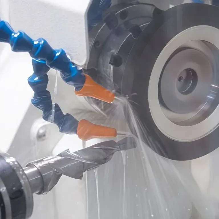
Heat generated during cutting affects tool wear, workpiece dimensional stability, and surface condition. Appropriate cooling and lubrication can reduce temperatures in the cutting zone, improve chip evacuation, and reduce friction between the tool and workpiece under suitable conditions. However, the cooling method must match the material, tool, and machining parameters. Increasing coolant flow alone does not guarantee a better surface finish.
- Maintain a stable coolant supply: For operations requiring coolant, ensure that it reaches the cutting zone effectively. Poor coolant positioning or inconsistent flow can cause localized temperature changes that affect tool life and machining consistency.
- Keep coolant clean: Chips, contaminants, and oil residues in coolant can affect machining conditions and increase the risk of surface scratches. Maintain filtration systems and inspect coolant condition regularly to support stable production.
- Adjust cooling methods to the material: Aluminum alloys, stainless steel, and titanium alloys have different cutting characteristics. Select cooling methods according to tool manufacturer recommendations and process conditions. Some operations depend more on effective chip evacuation and heat management than on simply increasing coolant volume.
- Prevent thermal effects on dimensions: For parts with tight tolerances, monitor temperature increases during continuous machining. When necessary, adjust cycle timing, cooling conditions, and inspection procedures to reduce the influence of temperature changes on dimensional measurements.
Coolant management should be integrated with equipment maintenance and process documentation. Stable cooling conditions help reduce abnormal tool wear and surface defects while improving quality consistency during continuous production.
Control Burrs, Scratches, and Residual Chips
Surface defects are not always caused by cutting parameters. Burrs, chip scratches, clamping marks, and handling damage can also affect appearance, assembly, and final acceptance. Precision-turned parts therefore require suitable protective measures throughout machining, cleaning, inspection, and packaging.
Burrs commonly occur at component edges, groove exits, and cutoff locations. They can be controlled by optimizing tool paths, adjusting cutting parameters, and applying appropriate deburring operations. For parts with small openings or complex edges, define acceptable chamfer dimensions and burr limits to prevent deburring from damaging critical features.
Chip scratches can occur during machining or during part handling, cleaning, and transfer. Removing chips from the workpiece and fixtures promptly, using suitable cleaning tools, and preventing metal parts from colliding can reduce unwanted scratches. Products with strict appearance requirements may also need protective separators or suitable packaging to prevent damage during transportation.
If a component requires anodizing, electroplating, or another surface treatment, confirm the relationship between the required surface roughness and the finishing process before machining begins. Some surface treatments cannot eliminate deep scratches or pronounced tool marks, so the required surface condition may need to be achieved during an earlier manufacturing stage.
CNC Turning Surface Roughness Inspection and Quality Management
A suitable machining process must be verified through inspection. For precision components with strict surface requirements, visual examination alone cannot accurately determine whether roughness meets drawing specifications. Selecting suitable measuring equipment, defining inspection locations, and implementing consistent process controls help evaluate machining results reliably and prevent nonconforming parts from reaching assembly.
Choose an Appropriate Surface Roughness Measurement Method
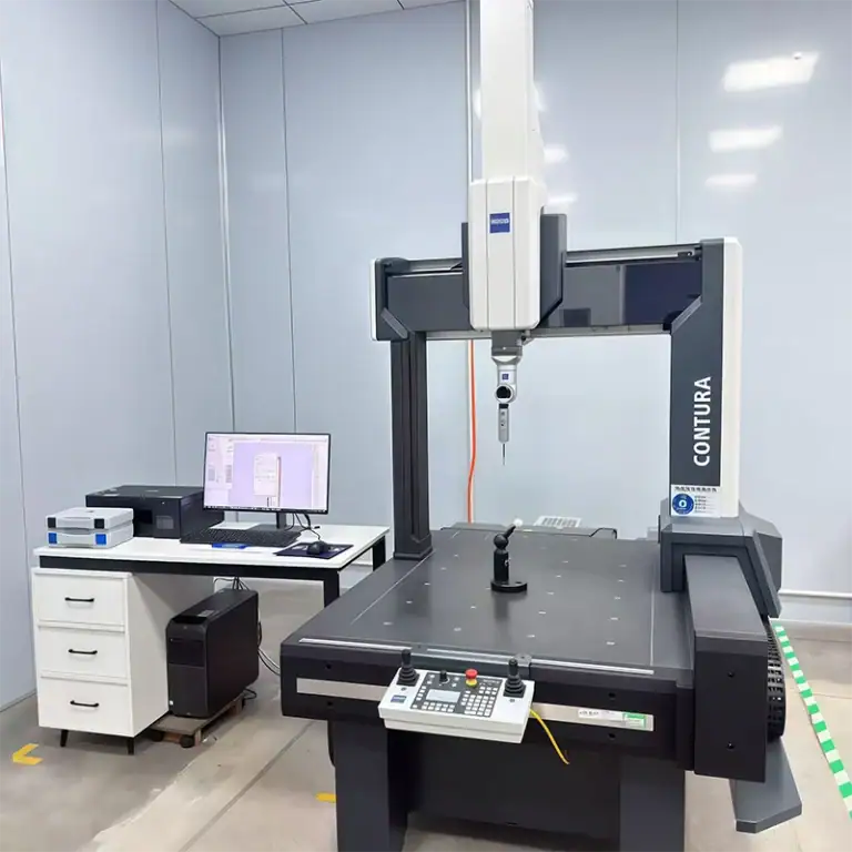
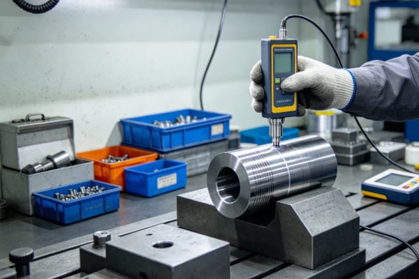
The inspection method should be selected according to component geometry, surface location, drawing parameters, and acceptance criteria. Common methods include contact profilometers that measure surface profiles and optical measuring equipment for surface analysis where appropriate.
- Contact surface roughness testers: A stylus moves along a specified measurement path to collect surface profile data and calculate roughness parameters. Select the correct measurement direction, evaluation length, and cutoff wavelength, and ensure that the workpiece is clean and securely positioned.
- Optical measuring equipment: For certain microstructures, specialized surfaces, or locations unsuitable for contact measurement, optical methods may be considered. Before use, verify the equipment’s measurement capability, applicable range, and compatibility with the drawing’s acceptance requirements.
- Standardize measurement conditions: Measurement location, direction, and workpiece condition can influence results. For cylindrical turned surfaces, determine the measurement direction according to applicable standards and drawing requirements, and use repeatable measurement locations.
- Calibrate and maintain equipment: Measuring instruments require regular calibration and maintenance. A worn stylus, abnormal equipment condition, or inconsistent operating procedures can cause measurement errors and unreliable quality assessments.
Inspection results should be compared with the parameters and applicable standards specified in the engineering drawing. If the drawing specifies Ra, Rz, or another parameter, inspect according to that requirement rather than treating different roughness parameters as interchangeable.
Establish First-Article Inspection and Process Monitoring
Consistent quality management should cover first-article approval, in-process inspection, and final acceptance. First-article inspection verifies whether the program, tooling, workholding method, and cutting parameters meet requirements. In-process inspection helps identify problems caused by tool wear, machine condition changes, or variations in machining conditions.
- First-article approval: Before batch production begins, inspect critical dimensions, surface roughness, threads, and relevant geometric tolerances. Once the results meet requirements, proceed with production using the verified process
- In-process sampling: Determine sampling frequency based on order volume, part risk, and quality requirements. For components sensitive to tool wear or requiring strict surface quality, monitor roughness changes closely and shorten inspection intervals when necessary.
- Traceability of defects: When surface quality fails to meet requirements, record the part batch, machine condition, tool usage, and machining parameters. Investigating the root cause and implementing corrective actions helps prevent recurring defects.
- Maintain quality records: For parts requiring consistent batch delivery, retain relevant inspection data, process revisions, and corrective-action records. These records support traceability and help verify quality on future orders.
Combining roughness inspection with machining process data makes it easier to detect quality trends early and reduce batch scrap and rework costs.
Choose a Reliable Precision CNC Turning Supplier
For businesses outsourcing precision turning, a supplier’s equipment capabilities, process experience, and quality management procedures directly affect the final surface finish. Purchasing decisions should consider more than the unit price. It is also important to confirm that the supplier has the machining and inspection capabilities needed to meet drawing requirements.
When evaluating suppliers, check whether they have CNC turning equipment suitable for the target materials and part geometry, whether they can develop appropriate tooling and cutting parameters, and whether they have suitable surface roughness measurement equipment. For components requiring precision fits, confirm that the supplier understands the specified dimensions, tolerances, and surface finish requirements and can provide the agreed inspection records.
When requesting a quotation, provide complete engineering drawings, material grades, roughness parameters, tolerance requirements, order quantities, and delivery schedules. If the product requires specific surface treatments, deburring standards, or inspection reports, communicate these requirements in advance. Clear technical information allows suppliers to evaluate process feasibility and reduces quotation errors and subsequent changes.
Consistent CNC turning surface quality depends on appropriate cutting parameters, suitable tooling, reliable workholding, effective cooling and lubrication, and standardized inspection procedures. Optimizing finishing operations, minimizing vibration, controlling tool wear, and measuring surface roughness regularly can improve the consistency and reliability of precision components. For custom machining projects, clearly defined drawing requirements and a supplier with proven process and quality control capabilities help balance machining accuracy, delivery schedules, and manufacturing costs.