G code is the instruction language that tells a CNC machine where and how to move. It controls tool positions, cutting paths, feed rates, coordinate modes, and other actions needed to turn a digital design into a physical part. Although most production programs are generated by CAM software, understanding the basic commands helps engineers and operators see how programming choices affect accuracy, cycle time, and machining risk.
This guide explains what G code is, how programs move from CAD and CAM to the machine controller, and how to read common commands. It also covers verification, common errors, and practical optimization methods that improve efficiency without sacrificing tool life or part quality.
What Is G Code And How Does It Work?
A CNC machine cannot directly interpret a 3D model or an engineering drawing. It needs a structured program that converts geometry into positions, speeds, and machine actions. G code provides this machine-readable link between a planned toolpath and the physical movement of the equipment.
What G Code Controls
G code is commonly used for geometric and preparatory commands. It can request a rapid approach, a controlled straight cut, a circular path, a drilling cycle, a coordinate system, or a compensation mode. Address words such as X, Y, and Z define linear positions, while A, B, and C may control rotary axes.
Other words add process information. F usually sets feed rate, S sets spindle speed, and T identifies a tool. G code works with M codes and controller-specific instructions that handle spindle operation, coolant, tool changes, pauses, and program completion.
How CNC Controllers Read G Code
A CNC controller reads the program in blocks, normally one line at a time. Each block contains words made from a letter and a value. For example, G01 X40.0 Y15.0 F300 requests a controlled linear move to the programmed position at the stated feed rate.
Many commands are modal, meaning they stay active until replaced by another command in the same group. A program can pass the controller’s syntax check and still be unsafe if the offsets, tools, coordinates, or feeds are wrong. Simulation and setup verification are therefore essential before cutting.
From CAD Model To Running G Code
Modern CNC programs usually begin with a CAD model and an engineering drawing. The model defines geometry, while the drawing communicates tolerances, surface finishes, threads, critical dimensions, and other requirements that influence the machining strategy.
Creating Toolpaths With CAD And CAM
The programmer imports the model into CAM software, defines the stock and work coordinate system, and selects the machine orientation. Tools, holders, feeds, speeds, stepovers, depths of cut, and entry methods are then assigned to roughing, finishing, drilling, tapping, and other operations.
CAM calculates the toolpaths and can display remaining stock or obvious interference. However, the programmer must still consider rigidity, chip evacuation, deformation, workholding, and tool access. A mathematically correct path may be inefficient or unstable if these manufacturing factors are ignored.
Using A Post Processor For The CNC Machine
A CAM toolpath is not yet machine-ready. A post processor converts it into NC code that matches a specific machine and controller. It defines syntax, program format, tool-change logic, work offsets, rotary-axis behavior, and supported cycles.
Not every CNC machine interprets code in the same way. A command may behave differently on a mill and a lathe, and controller brands may use different options. The post processor must match the actual machine configuration, and important output should be checked against the machine manual.
Loading, Simulating, And Running The Program
After post processing, the NC file is transferred to the CNC control. Before running it, the operator confirms the tools, offsets, stock position, fixture, workholding clearance, material, and program version. These details must match the assumptions used in CAM.
Simulation, graphics mode, single-block execution, reduced rapid speed, feed override, and dry runs help verify the sequence safely. Customers normally provide CAD files, drawings, material, quantity, and finish requirements rather than G code because the final program must match the supplier’s machines, tools, and fixtures.
How To Read A G Code Program
A G code file may look complicated, but its structure becomes easier to understand when each block is separated into motion mode, coordinates, process values, and auxiliary functions.
Program Blocks, Coordinates, Feed, And Spindle Speed
A block may begin with an optional sequence number such as N10. X, Y, and Z usually define linear-axis positions, while A, B, or C represent rotary axes. F sets feed rate, S specifies spindle speed, T calls a tool, and M codes control supporting machine functions.
Consider this simplified milling example:
G21 G17 G90
T1 M06
G54
S3000 M03
G00 X0 Y0
G43 H01 Z20.0
G01 Z-2.0 F150
G01 X40.0 F400
G00 Z20.0
M30
It selects metric units, the XY plane, and absolute positioning; loads a tool; activates a work offset; starts the spindle; approaches the part; applies tool-length compensation; makes a linear cut; retracts; and ends the program. It is an educational example and must be adapted before use on a real machine.
Absolute And Incremental Positioning
G90 normally selects absolute positioning. Coordinates are measured from the active program zero, so X40.0 means move to X40.0 in the current work coordinate system. This mode is easy to review because each command points to a defined location.
G91 normally selects incremental positioning, where each coordinate describes movement from the current position. Both modes are useful, but an unintended switch can shift every later move. Safe programs set the required mode clearly and restore it after local incremental operations.
G Code vs M Code
G codes mainly define motion, coordinate systems, units, compensation, and machining cycles. M codes control supporting functions such as spindle start and stop, coolant, tool changes, pauses, and program end.
The distinction is useful but not completely universal because controllers may support custom functions. In a block such as S3000 M03, the S word requests spindle speed and M03 starts spindle rotation. A later G01 command then controls the cutting movement.
Common G Code Commands
The most common commands cover movement, planes, units, positioning, offsets, compensation, and repetitive cycles. Exact syntax varies by controller, so the machine manual remains the final reference.
| Command | Function | Typical Use | Programming Note |
| G00 | Rapid positioning | Approaching or retracting | Confirm the path is clear |
| G01 | Linear interpolation | Straight cutting moves | Uses the active feed rate |
| G02 / G03 | Clockwise / counterclockwise arc | Circular profiles and radii | Requires the correct plane |
| G17 / G18 / G19 | Select XY / XZ / YZ plane | Arcs and fixed cycles | Changes how arc data is read |
| G20 / G21 | Inch / metric units | Sets program units | Verify before any motion |
| G90 / G91 | Absolute / incremental positioning | Controls coordinate meaning | Unexpected changes shift later moves |
| G54-G59 | Work coordinate systems | Locates the part zero | Must match the setup |
| G40 / G41 / G42 | Cancel / left / right cutter compensation | Adjusts for tool radius | Needs suitable lead moves |
| G43 | Tool-length compensation | Corrects for tool length | Call the correct H offset |
| G81-G89 | Common canned cycles | Hole-making operations | Details vary by controller |
G00, G01, G02, And G03 Motion Commands
G00 rapidly positions the axes when the tool is not cutting. It saves cycle time, but the path must be clear because several axes may move together. G01 creates a straight cut at the active feed rate and is used for many milling and turning movements.
G02 and G03 create clockwise and counterclockwise circular interpolation. The programmer defines the endpoint and either the center or radius of the arc. The selected plane—G17, G18, or G19—determines which axes form the circle.
G17, G18, G19, G20, G21, G90, And G91
G17 normally selects the XY plane, G18 the XZ plane, and G19 the YZ plane. Plane selection affects arcs and some fixed cycles. The wrong plane may produce an alarm or move the tool in an unintended orientation.
G20 and G21 select inch and metric units, while G90 and G91 select absolute and incremental positioning. These modes remain active until changed, so reliable programs state them clearly near the start and before critical operations.
Work Offsets, Tool Compensation, And Canned Cycles
Work offsets such as G54 through G59 connect the programmed zero to the real location of the part. Tool-length compensation corrects for the installed tool length, while cutter compensation allows controlled contour adjustments based on tool radius.
Canned cycles combine repeated hole-making actions into compact commands. They can control approach, feed depth, retract level, and repeated positions. They reduce program length, but the programmer must understand the controller’s cycle parameters and retract behavior.
Common G Code Errors And Program Verification
Most failures result from a mismatch between the program and the physical setup rather than one unfamiliar command. Wrong offsets, tools, stock locations, or machine assumptions can turn valid code into a collision or rejected part.
Coordinate, Offset, Feed, And Spindle Errors
Incorrect signs, decimal points, units, or positioning modes can send the tool to the wrong location. Work and tool offset mistakes are especially dangerous because the graphical toolpath may look correct while the real machine zero is wrong.
Feed and spindle values must suit the tool, material, operation, and machine. Aggressive values may break tools or distort parts, while overly cautious settings can cause rubbing, heat, poor finish, and long cycle times. Programs should set safety-critical modes explicitly instead of relying on previous machine states.
Tool, Fixture, And Machine Collisions
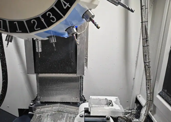
Possible collisions include the cutter entering a clamp, the holder touching a wall, the spindle approaching the fixture, or a rotary table moving the part into the machine structure. Multi-axis programs require extra attention because more components move through the work envelope.
Verification is stronger when it includes the actual tool assembly, stock, fixture, machine travels, and rotary limits. The setup sheet must also match the program; a correct toolpath can still fail if the operator installs the wrong holder, tool length, jaw position, or fixture orientation.
Simulation, Dry Runs, And First-Part Inspection
Verification should begin in CAM and continue at the machine. Backplotting checks the path, while machine simulation can include axis limits, rotary motion, fixtures, and collision geometry. Whenever possible, the posted NC file should be verified rather than only the original CAM path.
At the machine, single block, distance-to-go displays, reduced rapid rates, and feed overrides help prove out the program. The first finished part should then be inspected against the drawing to confirm dimensions, hole locations, surface finish, tool wear, workholding, and datum relationships.
How To Optimize G Code?
Optimization is not simply shortening the file. The aim is to reduce non-cutting time and improve consistency without making the process harder to verify or less stable.
Reducing Unnecessary Moves And Tool Changes
Efficient programs limit excessive retracts, repeated positioning, and avoidable rapid travel. Clearance heights should protect the tool and fixture without forcing every operation to spend unnecessary time moving through air.
Operations can be grouped by tool to reduce tool changes, but machining order must still control distortion, protect datums, and maintain rigidity. The shortest path is not always the safest, so optimization should preserve clear retracts and practical safety margins.
Balancing Cycle Time, Tool Life, And Surface Finish
Higher feeds do not automatically produce lower cost. Cutting conditions must match chip load, tool engagement, spindle power, material behavior, and coolant delivery. Excessive parameters can increase tool replacement and scrap.
Toolpaths with stable engagement and controlled cornering can improve both cycle time and tool life. Finishing passes should use suitable stepovers and tool contact to achieve the drawing requirement rather than chasing unnecessary surface quality on noncritical areas.
Using Canned Cycles And Subprograms
Canned cycles reduce repeated code for drilling, reaming, and tapping. Subprograms and loops are useful when a feature pattern repeats, allowing the main program to call a verified sequence at different positions.
Compact code is valuable only when it remains understandable. Macros and subprograms should use clear comments, controlled variables, and defined limits so later edits do not create unexpected motion.
G Code Applications In CNC Machining
G code supports many CNC processes, but the coordinate system, tool motion, and available functions change with the machine type. The same basic ideas—positions, feeds, speeds, offsets, and safe motion—apply across these applications.
| CNC Process | Typical G Code Use |
| CNC milling | Controls pockets, contours, slots, drilling, and surfaces |
| CNC turning | Controls facing, diameter cutting, grooving, boring, and threading |
| Drilling and tapping | Positions holes and runs fixed cycles |
| Multi-axis machining | Coordinates linear and rotary axes for complex features |
| CNC routing | Controls cutting paths in plastics, wood, and composites |
The program must always be generated and verified for the exact controller, machine configuration, tooling, and workholding method.
FAQs
How To Convert STL To G Code?
Import the STL file into CAM or slicing software, set the machine, material, tools, and machining parameters, then generate the toolpath and export it with the correct post processor.
What Is G Code Programming?
G Code programming is the process of creating instructions that control CNC machine movement, coordinates, feed rate, spindle speed, and machining operations.
What Are G And M Codes?
G codes mainly control tool movement and machining modes, while M codes control auxiliary machine functions such as spindle start, coolant, tool changes, and program stops.
Conclusion
G code converts machining intent into controlled CNC movement, but reliable results depend on more than command names. The program must match the controller, tooling, offsets, fixture, material, and drawing requirements. A correct post processor, machine-aware simulation, cautious prove-out, and first-part inspection work together to reduce collisions, scrap, and unnecessary cycle time.
At TiRapid, we provide precision CNC machining and manufacturing services for prototypes and low-volume parts. Our team combines CAD/CAM programming, process planning, toolpath verification, controlled setups, and dimensional inspection to produce accurate components across a wide range of metals and engineering plastics.