A chamfered edge is a flat, angled surface created by cutting away a sharp corner from a part. In manufacturing, chamfering is used to make edges safer, easier to assemble, less likely to chip, and more suitable for finishing or functional contact.
In this guide, we explain what is a chamfered edge, what chamfer meaning is in engineering, how chamfered edges differ from fillets, bevels, and rounded edges.
What Is a Chamfered Edge?
A chamfered edge is an angled cut between two surfaces of a part, usually replacing a sharp 90-degree corner with a flat sloped surface. It is commonly used in metal, plastic, stone, ceramic, and composite parts to improve safety, assembly, and edge durability.
A chamfer can appear on external edges, hole openings, slots, threads, pockets, and part corners. In engineering drawings, chamfers are often defined by angle and distance, such as 1 mm × 45°, or by two linear dimensions depending on drawing standards.
The simplest way to understand a chamfered edge is this: instead of leaving a sharp corner, the manufacturer removes a small diagonal section. That angled surface helps the part look cleaner, feel safer, and work better during assembly.
Chamfer Edge Shape, Angle, and Dimensions
A chamfer edge usually has a straight sloped shape, a defined angle, and a controlled size. The most common chamfer angle is 45°, but other angles such as 30° or 60° may be used depending on assembly, clearance, tool access, and design function.
Chamfer dimension is usually shown on drawings as a distance and angle. For example, “C1” may indicate a 1 mm chamfer, while “1 × 45°” means a 1 mm chamfer at a 45-degree angle. Some drawings may define the chamfer by two linear distances instead.
How to read chamfer dimensions depends on the drawing standard and note format. Engineers should confirm whether the dimension controls chamfer width, depth, angle, or both legs of the angled surface, especially when the chamfer affects fit or assembly.
Why Are Chamfered Edges Used?
Chamfered edges are used to improve safety, assembly, durability, edge protection, appearance, and manufacturing quality. They remove sharp corners and create controlled transitions that make parts easier to handle and easier to use.
Improving Safety and Handling Comfort
Chamfered edges improve safety by removing sharp corners that could cut hands, damage packaging, or scratch adjacent parts. This is one of the most common reasons to add a chamfer to machined components.
In handled parts, even a small edge break can improve comfort. Sharp metal or plastic corners may feel rough, while a chamfer provides a cleaner and safer transition.
For industrial components, safety is not only about users. Chamfers also reduce the chance of edge damage during shipping, assembly, maintenance, and equipment installation.
Simplifying Assembly and Installation
Chamfered edges simplify assembly by helping parts align, enter, and seat more smoothly. A chamfer around a hole can guide screws, pins, shafts, or fasteners into position without catching on the sharp edge.
In precision assemblies, chamfers can reduce interference between mating parts. For example, a shaft entering a bore or a pin entering a hole may assemble more reliably when the hole opening is chamfered.
Chamfers also help during manual assembly. Operators can install parts faster when lead-in edges are designed clearly, especially in repetitive production or tight assembly spaces.
Reducing Edge Chipping and Damage
Chamfered edges reduce chipping and damage by removing the fragile sharp corner from the part. Sharp corners are more likely to crack, break, dent, or chip during machining, handling, or service.
This is important for metals, plastics, stone, ceramics, and brittle materials. A controlled chamfer can protect the edge and make the part more durable in contact or impact-prone areas.
For CNC machined parts, chamfers also help remove burrs left by drilling, milling, or turning. A clean chamfered edge improves part quality and reduces the need for extra manual finishing.
Improving Durability and Stress Distribution
Chamfered edges can improve durability by reducing sharp edge weaknesses and helping the part resist local damage. However, for major stress distribution, a fillet is often better than a chamfer because a rounded radius reduces stress concentration more smoothly.
Chamfers are still useful where the main concern is edge protection, assembly fit, or burr removal. They can reduce minor stress risers and protect corners from cracking during handling.
For highly loaded parts, engineers should not rely on chamfers alone. Critical load paths, fatigue zones, and internal corners may need fillets, radii, or other structural design improvements.
Enhancing Appearance and Finishing Quality
Chamfered edges enhance appearance by making parts look clean, intentional, and professionally finished. A part with controlled chamfers often looks more complete than one with raw sharp edges.
Chamfers also improve finishing quality by making edges easier to coat, anodize, polish, bead blast, or deburr. Sharp corners may hold burrs or coating defects, while chamfered edges are easier to finish consistently.
For visible parts, chamfer size should be consistent across the component. Uneven chamfer width can make an otherwise accurate part look poorly manufactured.
Common Types of Chamfering
Common types of chamfering include C-chamfers, R-chamfers, hole chamfers, thread chamfers, external edge chamfers, and internal corner chamfers. Each type serves a different function in manufacturing and assembly.

C-Chamfer
A C-chamfer is a straight angled chamfer, usually defined by size and angle. It is one of the most common chamfer types in CNC machining and engineering drawings.
For example, C1 or 1 × 45° indicates a small flat chamfer along an edge. This type is commonly used for external edges, hole openings, slots, and machined corners.
C-chamfers are practical because they are easy to machine, inspect, and repeat. They are suitable for most standard edge-breaking and assembly lead-in requirements.
R-Chamfer
An R-chamfer is a rounded edge treatment that uses a radius instead of a straight flat cut. Although it is sometimes grouped with chamfering in general discussions, it is closer to a fillet or radius edge.
R-chamfers are useful when a smoother transition is needed for touch comfort, stress reduction, flow, or appearance. They are common on consumer products, medical device housings, molded parts, and parts that require soft handling.
Compared with a C-chamfer, an R-chamfer may need different tooling or toolpaths. It can also increase machining time if a precise radius is required.
Hole Chamfer
A hole chamfer is an angled edge around the opening of a hole. It helps remove burrs, improve fastener entry, guide pins or shafts, and protect the hole edge from damage.
A chamfered hole is common in drilled, bored, reamed, or tapped features. It is especially useful when screws, dowel pins, shafts, or bearings need to enter the hole smoothly.
Hole chamfers must be controlled carefully when they affect seating surfaces or countersink-like functions. If the chamfer is too large, it may reduce contact area or weaken the surrounding edge.
Thread Chamfer
A thread chamfer is an angled entry at the beginning of a threaded hole or threaded shaft. It helps screws start smoothly and reduces the risk of cross-threading or damaged threads.
Thread chamfers are common on tapped holes, threaded shafts, nuts, inserts, and fastener features. They also improve assembly speed and reduce wear during repeated fastening.
For precision threaded components, the chamfer should be large enough to guide the fastener but not so large that it removes too much functional thread engagement.
External Edge Chamfer
An external edge chamfer is an angled cut along the outside edge of a part. It is commonly used to remove sharp corners, improve handling safety, and create a cleaner appearance.
External edge chamfers are found on plates, brackets, housings, blocks, covers, fixtures, and custom CNC machined components. They can be applied by milling, turning, grinding, routing, or manual finishing.
The chamfer size should match the part function. A small edge break may be enough for safety, while a larger chamfer may be needed for assembly clearance or visual design.
Internal Corner Chamfer
An internal corner chamfer is an angled edge inside a pocket, slot, recess, or internal feature. It can improve tool access, reduce burrs, and help mating parts fit more easily.
Internal chamfers are more difficult than external chamfers because tool access may be limited. Small internal corners may require special cutters, smaller tools, or additional toolpaths.
When designing internal chamfers, engineers should consider cutter reach, tool diameter, wall thickness, and inspection access. Overly complex internal chamfers can increase cost quickly.
How to Make a Chamfered Edge?
A chamfered edge can be made by CNC milling, turning, drilling, countersinking, grinding, routing, manual deburring, or finishing tools. The best method depends on material, geometry, chamfer size, tolerance, and production volume.
CNC Milling
CNC milling chamfers are made by using a chamfer mill, spot drill, end mill toolpath, or angled cutter to cut a controlled sloped surface along an edge. This method is common for plates, brackets, housings, pockets, slots, and complex machined parts.
Milling is flexible because chamfers can be added to many part features in one setup. CNC programs can control chamfer width, depth, and angle repeatedly across multiple parts.
For precision chamfers, toolpath strategy matters. Tool runout, cutter wear, feed rate, part fixturing, and material hardness all affect final chamfer quality.
CNC Turning
Turning chamfers are made on a lathe by cutting an angled edge on a cylindrical part. This is common for shafts, bushings, spacers, sleeves, pins, rollers, and round housings.
A turning chamfer can help parts insert into bores, reduce sharp edges, improve assembly, and protect threaded or cylindrical features. It can be cut with a turning tool, grooving tool, or form tool.
For turned parts, chamfer consistency depends on tool geometry, machine setup, part rigidity, and cutting parameters. Small chamfers are often added at both ends of round parts for safety and assembly.
Drilling and Hole
Drilling and hole chamfering create angled entries around drilled, tapped, or bored holes. This process may use a countersink, chamfer tool, spot drill, or dedicated front-and-back chamfering tool.
Hole chamfering is important because drilling often leaves burrs at hole openings. A chamfer removes those burrs and helps screws, pins, or shafts enter more smoothly.
For through holes, both front and back edges may need chamfering. Back-side chamfering can require special tools or secondary operations if the part cannot be flipped easily.
Manual Deburring and Finishing
Manual deburring and finishing can create small chamfered edges by using hand tools, files, scrapers, abrasive pads, deburring blades, or rotary tools. This method is common for small edge breaks and low-volume parts.
Manual chamfering is flexible, but it is less consistent than CNC machining. Operator skill can affect chamfer size, edge quality, and appearance.
For precision parts, manual finishing should be controlled with clear requirements. If chamfer size is critical, CNC machining or defined inspection may be better than freehand deburring.
Chamfering Tools and Cutters
Chamfering tools and cutters include chamfer mills, countersinks, spot drills, deburring tools, angled end mills, form tools, turning tools, and special drill-chamfer tools. The right tool depends on geometry and material.
Hard materials may require carbide tools, rigid setups, and controlled cutting parameters. Soft materials may require sharp tools and good chip evacuation to avoid smearing or poor surface quality.
Tool selection affects chamfer consistency, surface finish, burr formation, and machining time. A simple chamfer can become expensive if the wrong tool or setup is used.
Chamfering in CNC Machining
Chamfering in CNC machining is used to remove sharp edges, improve assembly, control hole entries, protect features, and create a cleaner finished part. It is one of the most common secondary or integrated operations in machined components.
Screws and Fasteners
Chamfered holes for screws and fasteners help guide assembly and reduce burrs around hole openings. They make it easier for screws, pins, bolts, and shafts to enter the hole without catching on a sharp edge.
A chamfered hole is not always the same as a countersink. A countersink is usually designed for a screw head to sit flush, while a chamfer may simply break the edge or guide the fastener.
The required chamfer dimension depends on the fastener type, hole size, material, and assembly method. Overly large chamfers can reduce contact area or weaken the hole edge.
Part Assembly
Chamfered edges for part assembly help components slide, align, and fit together more smoothly. They are especially useful when a part must enter a slot, housing, bore, fixture, or mating component.
Assembly chamfers reduce the risk of interference caused by sharp corners. They can also make manual assembly faster and reduce the chance of damaged surfaces.
For tight assemblies, chamfer direction and size should be defined clearly. A chamfer on the wrong edge may not solve the assembly issue, while a missing chamfer may cause fit problems.
Edge Protection
Chamfers for deburring and edge protection remove sharp burrs and fragile corners after machining. This improves safety, handling, packaging, and part durability.
Deburring chamfers are often small, such as a light edge break. They do not always need tight tolerances unless the edge is part of a functional assembly.
For visible or high-quality parts, chamfer consistency is important. Uneven deburring can make a machined part look inconsistent even if its main dimensions are correct.
Surface Finish
Chamfers can improve surface finish by creating clean transitions between machined surfaces and reducing ragged edges. They help make the part look more controlled and professionally finished.
On metal parts, chamfers can improve anodizing, plating, coating, or bead blasting quality by reducing sharp corners. On plastic parts, chamfers can reduce stress whitening, burrs, and edge roughness.
The surface finish of the chamfer itself depends on tool sharpness, feed rate, material, and cutting method. A poor chamfer can still create visible tool marks or burrs if not machined properly.
Chamfer Width, Depth, and Angle Control
Chamfer width, depth, and angle control are important when the chamfer affects fit, appearance, or function. A small uncontrolled edge break may be acceptable for deburring, but a functional chamfer needs clear specifications.
Common chamfer angles include 45°, 30°, and 60°. The most common drawing style is size × angle, such as 0.5 mm × 45° or 1 mm × 45°.
If a chamfer is critical, it should be dimensioned and toleranced on the drawing. If it is not critical, a general note such as “break sharp edges” may be enough.
Materials Suitable for Chamfering
Most machinable materials can be chamfered, including metals, plastics, stone, ceramics, composites, and engineered materials. The process and tool choice depend on hardness, brittleness, toughness, heat sensitivity, and required finish.
| Material Type | Typical Materials | Chamfering Suitability | Key Machining Considerations | Common Applications |
| Metals | Aluminum, stainless steel, carbon steel, brass, copper, titanium | Very suitable | Harder metals require rigid setups, sharp tools, proper cutting speed, and good burr control. Stainless steel and titanium need better heat and tool wear management. | CNC housings, brackets, shafts, plates, threaded parts, aerospace and industrial components |
| Engineering Plastics | POM, nylon, ABS, PC, PMMA, PEEK, PTFE, PVC | Suitable | Plastics need sharp tools, light cutting force, and heat control. Soft plastics may smear, while brittle plastics may chip if the tool is dull. | Plastic housings, bushings, covers, insulators, medical device parts, electronic components |
| Stone and Concrete | Granite, marble, engineered stone, concrete panels | Suitable | Brittle edges require diamond tools, controlled feed, and polishing when appearance matters. Chamfers help reduce edge chipping. | Countertops, tiles, slabs, architectural panels, decorative edges |
| Ceramics | Alumina, zirconia, technical ceramics, ceramic tiles | Suitable but challenging | Ceramics are hard and brittle, so diamond grinding tools, low vibration, and careful edge control are important. | Wear parts, insulating parts, tiles, precision ceramic components |
| Composites | Carbon fiber, fiberglass, FR4, G10 | Suitable with caution | Fiber pull-out, delamination, and dust control are key issues. Sharp tools and proper extraction are needed. | Aerospace panels, electronic boards, structural composite parts, insulation plates |
| Soft Materials | Soft aluminum, copper, PE, PP, rubber-like plastics | Suitable but needs control | Soft materials may deform, smear, or leave burrs. Stable fixturing and sharp cutting edges are important. | Covers, seals, soft pads, protective parts, low-load components |
| Hard Materials | Hardened steel, titanium, ceramics, carbide-related materials | Suitable but higher cost | Hard materials increase tool wear and machining time. Rigid tooling, carbide or diamond tools, and controlled parameters are required. | High-wear parts, precision tooling, aerospace components, industrial wear parts |
Common Chamfering Challenges and Solutions
Common chamfering challenges include chatter, uneven chamfer width, burrs, poor edge quality, chip control problems, tool wear, and tool rigidity issues. These problems can affect appearance, tolerance, assembly, and part consistency.
Chatter During Chamfering
Chatter during chamfering is vibration that creates poor surface finish, inconsistent chamfer width, and tool marks. It often happens when the tool, workpiece, or setup lacks rigidity.
Chatter can be reduced by improving fixturing, using a more rigid tool holder, lowering tool overhang, adjusting spindle speed, reducing feed, or using a sharper cutter.
In CNC machining, chatter should be corrected early because it can affect both the chamfer and adjacent surfaces. It may also shorten tool life.
Uneven Chamfer Width
Uneven chamfer width happens when the toolpath, part setup, surface variation, or manual process is not consistent. It can make the part look poor and may affect assembly if the chamfer is functional.
Uneven chamfers are common when parts are manually deburred or when surfaces are not aligned correctly during CNC machining. Tool wear can also change chamfer size over a batch.
Solutions include better fixturing, consistent toolpath depth, tool wear monitoring, and inspection of first articles before full production.
Burrs and Poor Edge Quality
Burrs and poor edge quality can occur when the cutting tool is dull, the material smears, chip evacuation is poor, or cutting parameters are incorrect. A chamfer should remove burrs, not create new ones.
Metals may form burrs if feed and tool geometry are not controlled. Plastics may smear or melt if heat is too high. Brittle materials may chip if cutting force is excessive.
Solutions include sharp tools, proper speeds and feeds, coolant or air blast when suitable, and matching tool geometry to material behavior.
Chip Management Issues
Chip management issues occur when chips collect around the chamfer tool, scratch the surface, damage the edge, or reduce cutting quality. This is common in deep features, small holes, soft materials, and internal chamfers.
Good chip evacuation helps maintain a clean chamfer and protects the tool. Air blast, coolant, peck cycles, toolpath adjustment, and correct cutter geometry can help.
For chamfered holes and internal features, chip control is especially important because trapped chips can damage hole edges or threads.
Tool Wear and Tool Rigidity
Tool wear and tool rigidity directly affect chamfer accuracy, surface finish, and consistency. A worn chamfer tool may create burrs, uneven width, or poor surface quality.
Hard materials increase tool wear faster, while long tool overhang reduces rigidity and increases chatter risk. Small chamfer tools can also be sensitive to runout.
Good practice includes using appropriate tool material, checking tool wear regularly, minimizing overhang, and replacing tools before quality drops.
Cost Considerations for Chamfering
Chamfering cost depends on complexity, tolerance, material, tooling, setup, inspection, and production volume. Simple chamfers are usually low-cost, but complex or tightly controlled chamfers can add machining time.
Complexity and Machining Time
Chamfer complexity increases machining time when the part has many edges, internal corners, small features, or difficult tool access. External chamfers are usually easier than internal or backside chamfers.
Simple 45-degree chamfers are generally efficient. Nonstandard angles, variable chamfers, very small chamfers, or multiple different sizes can increase tool changes and programming time.
To reduce cost, use standard chamfers where possible and avoid adding chamfers to nonfunctional edges unless safety or appearance requires them.
Tolerance Requirements and Inspection Cost
Tight tolerance requirements increase inspection cost because chamfer size and angle must be measured more carefully. Noncritical edge breaks usually do not need strict tolerances.
If a chamfer controls assembly fit, sealing, fastener entry, or visible appearance, tolerance may be necessary. If it only removes sharpness, a general edge break note may be enough.
Clear drawing notes help suppliers understand which chamfers are critical and which are only for deburring. This improves cost control and avoids unnecessary inspection.
Material Hardness and Tooling Cost
Material hardness affects tooling cost because harder materials wear tools faster and may require slower cutting speeds. Stainless steel, titanium, ceramics, and hardened materials can make chamfering more expensive than aluminum or plastic.
Soft materials can also create cost challenges if they smear, deform, or need special support. The cost is not only about hardness, it is about how the material behaves during cutting.
Tool selection should match material behavior. Using the wrong tool can increase burrs, tool wear, scrap risk, and finishing time.
Production Volume and Cost Efficiency
Production volume affects chamfering cost because setup and programming time can be spread across more parts in larger batches. For prototypes, each extra chamfer may have a higher relative cost.
In production runs, automated chamfering can be efficient if the design is standardized. Consistent chamfer sizes and tool access improve repeatability and reduce cycle time.
For low-volume custom parts, avoid unnecessary decorative chamfers unless they improve function or appearance enough to justify the cost.
Chamfer vs Fillet vs Bevel vs Bullnose
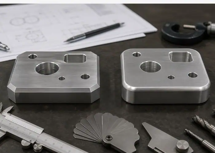
Chamfer, fillet, bevel, and bullnose are different edge treatments used for different design purposes. A chamfer is a flat angled edge, a fillet is a rounded edge, a bevel is usually a longer angled surface, and a bullnose is a large rounded edge profile.
Chamfer vs Fillet
The main difference between chamfer vs fillet is shape. A chamfer is a straight angled cut, while a fillet is a rounded transition. Chamfers create flat sloped faces, while fillet edges create smooth curved radii.
Chamfers are often faster and simpler to machine because they can be cut with chamfer mills, countersinks, turning tools, or standard toolpath strategies. Fillets may require radius tools, ball end mills, or more complex toolpaths, especially on internal features.
Choose a chamfer when you need easy assembly, fast deburring, screw lead-in, or a clean angled edge. Choose a fillet when stress reduction, flow improvement, comfort, or smooth rounded appearance is more important.
Chamfer vs Bevel
The main difference between chamfer and bevel is how the term is used. A chamfer is usually a small angled edge added to remove a sharp corner, while a bevel often describes a larger angled cut or sloped surface between two faces.
In many workshops, the words may overlap. However, in precision manufacturing, chamfer usually refers to a defined edge break or controlled angled feature, while bevel may refer to a more visible slanted face used for design, welding, joining, or appearance.
In taper vs chamfer comparisons, a taper usually changes diameter or thickness gradually over a length, while a chamfer is a short angled transition at an edge. A taper is often a functional geometry,a chamfer is usually an edge treatment.
Chamfer vs Bullnose
The main difference between chamfer and bullnose is that a chamfer is flat and angled, while a bullnose is fully rounded. Bullnose edges are common in stone, countertops, tiles, furniture, and consumer products where touch comfort and appearance matter.
A chamfer is usually easier to machine and inspect in metal and plastic parts. A bullnose edge may require more shaping, polishing, or profile tooling, especially in stone, ceramic, or decorative surfaces.
Choose chamfered edges for practical manufacturing, fast assembly, and controlled edge breaks. Choose bullnose edges when appearance, touch comfort, and rounded protection are the main priorities.
How to Choose the Right Edge Type
The right edge type should be chosen based on function, material, manufacturing method, cost, and appearance. Chamfers are best for simple edge breaks, assembly lead-ins, and cost-efficient machining. Fillets are better for stress distribution and smooth transitions.
If the part must mate with another component, a chamfer can help guide assembly. If the part must resist fatigue or stress concentration, a fillet may be better. If the part is decorative or handled frequently, a rounded or bullnose edge may improve comfort.
A good design review should ask: Does the edge need to be safe, strong, smooth, precise, attractive, or low-cost? The answer determines whether chamfer, fillet, bevel, or bullnose is the best choice.
How to Design Chamfers for Better Manufacturing?
Chamfers should be designed for better manufacturing by keeping them functional, practical, standardized, and matched to the material and process. Good chamfer design improves part quality without adding avoidable machining cost.
Use Chamfers Only Where They Improve Function
Chamfers should be used where they improve function, safety, assembly, edge protection, or appearance. They should not be added to every edge automatically if they do not improve the part.
Functional chamfers include screw lead-ins, hole entries, mating edges, handled edges, and edges prone to chipping. Nonfunctional chamfers may only add machining time.
A good drawing should distinguish between required chamfers and general deburring. This helps the manufacturer focus control on the features that matter.
Keep Chamfer Sizes Practical
Chamfer sizes should be practical for the part size, material, and manufacturing process. Very tiny chamfers may be hard to inspect, while overly large chamfers may weaken edges or interfere with mating parts.
Standard sizes such as small 45-degree edge breaks are usually easier to produce. Large decorative chamfers or tight-angle chamfers may require more toolpath time.
Practical chamfer design improves quality and reduces cost. If a chamfer does not need tight control, avoid specifying unnecessary precision.
Match Chamfer Design to Material and Process
Chamfer design should match material and process because different materials respond differently to cutting, grinding, routing, or polishing. Metals, plastics, stone, and ceramics do not behave the same way.
For CNC metal parts, tool rigidity and burr control matter. For plastic parts, heat and deformation matter. For stone and ceramic parts, chipping and edge finish matter.
Before finalizing a chamfer, engineers should consider whether the selected process can produce the desired edge consistently and economically.
Confirm Critical Chamfers with Your Manufacturer
Critical chamfers should be confirmed with your manufacturer before production because tool access, inspection methods, and material behavior may affect feasibility. A drawing may look simple, but the actual setup can be difficult.
This is especially important for internal chamfers, backside chamfers, hole chamfers, hard materials, thin walls, and cosmetic parts. Early review can prevent delays and rework.
A short design-for-manufacturing review helps confirm chamfer size, angle, tolerance, and cost before machining begins.
Common Mistakes to Avoid
Common chamfer design mistakes happen when chamfers are specified without considering function, process, material, or inspection. Poor chamfer design can increase cost or create assembly problems instead of solving them.
Avoid these mistakes:
- Adding chamfers to every edge without functional reason
- Using overly tight chamfer tolerances on noncritical edges
- Confusing chamfer vs fillet on drawings
- Specifying a chamfer where a radius is needed for stress relief
- Making internal chamfers difficult to access with standard tools
- Ignoring tool wear when chamfering hard materials
- Ignoring burrs after chamfered hole machining
- Using inconsistent chamfer sizes across similar features
- Specifying decorative chamfers without considering cost
- Failing to define critical chamfers clearly
- Assuming all chamfers are 45 degrees
- Ignoring how chamfer size affects mating surfaces
FAQs
What Does A Chamfer Edge Look Like?
A chamfer edge looks like a flat angled cut between two surfaces. Instead of a sharp 90° corner, the edge is cut at a slope, commonly 45°. For example, a 1mm × 45° chamfer creates a small diagonal face along the corner. On holes, a chamfer appears as a sloped entry around the opening, helping screws, pins, or shafts enter more smoothly.
What Is The Purpose Of Chamfer Edges?
The purpose of chamfer edges is to remove sharp corners, improve safety, simplify assembly, and reduce edge damage. In CNC machining, chamfers are often used on holes, threads, slots, and external edges. A common chamfer such as 0.5mm–1mm × 45° can reduce burrs, improve handling, guide fasteners, and make machined parts look cleaner and more professional.
Are Bevelled And Chamfered The Same?
Bevelled and chamfered are similar, but not always the same. A chamfer is usually a small angled edge used to remove a sharp corner, often for machining, assembly, or safety. A bevel can be a larger angled surface used for design, welding, joining, or appearance. In simple terms, all chamfers are angled edges, but not every bevel is a small engineering chamfer.
Conclusion
Chamfered edges are simple but important design features that improve safety, assembly, durability, appearance, and CNC part quality. A chamfer edge removes sharp corners and creates a controlled angled transition that can help parts fit better, resist damage, and look more professionally finished. The best chamfer design depends on material, function, tolerance, tool access, and cost.
At TiRapid, we provide precision CNC machining services for custom metal and plastic components. If your part requires chamfered holes, clean edge breaks, tight-tolerance features, or custom surface finishing, upload your drawing or share your requirements to get a tailored manufacturing solution.