
As a core process in modern mechanical manufacturing, CNC turning bears the key responsibility of producing high-precision shafts, discs, and complex rotary components. With increasingly stringent tolerance requirements across the aerospace, medical device, and new energy vehicle industries, mastering systematic cutting parameter configuration, tool geometry selection, and challenging workpiece processing control techniques is essential for enhancing efficiency, improving quality, and reducing total per-unit manufacturing costs.
Core Cutting Parameter Matching and Efficiency Optimization
The scientific adjustment of the three cutting elements—cutting speed (Vc), feed rate (f), and depth of cut (ap)—directly determines machining efficiency, surface roughness, and tool life. Excessively high parameters can lead to severe tool wear, whereas conservative parameters significantly prolong single-piece cycle times.
The Decisive Impact of Cutting Speed (Vc) on Cutting Heat and Tool Life
Cutting speed control is the most direct technical method to balance workpiece surface processing quality with tool durability. Implementing targeted cutting speed matching according to different material characteristics allows for maximized machining efficiency and minimized tool wear costs:
- Aluminum Alloys (e.g., 6061-T6): The recommended cutting speed range is set between 300 and 800 m/min, which can be further increased to over 1000 m/min when paired with high-pressure coolant. An appropriately high cutting speed significantly reduces the single-piece machining cycle time.
- Stainless Steel (e.g., 316L): The recommended cutting speed is reduced to 120 – 180 m/min to manage heat accumulation and extend the active life of the tool coating. Controlling the cutting speed effectively lowers the risk of early tool breakage caused by work hardening.
- Titanium Alloys (e.g., TC4 / Ti-6Al-4V): The recommended cutting speed is strictly restricted to 40 – 80 m/min to prevent chemical affinity interactions between titanium and tool materials at elevated temperatures. Combining low cutting speeds with high-flow coolant is the critical factor for ensuring process safety in titanium alloy turning.
Scientific configuration of cutting speed serves as the primary line of defense against cutting heat accumulation and must be fine-tuned dynamically based on the thermal conductivity of the workpiece material.
Feed Rate (f) and Theoretical Surface Roughness (Ra) Mathematical Derivation and Control
Feed rate dictates the cross-sectional area of the chip generated per unit time and serves as the key parameter directly controlling surface texture depth. The theoretical surface roughness formula is derived as follows:Rz ≈ (f² / (8 · rε)) × 1000 (μm)
In actual turning production, rough machining typically uses a larger corner radius (such as rε = 0.8 mm or 1.2 mm) to withstand impact loads, with the feed rate set between 0.25 and 0.45 mm/rev. For finish machining aimed at achieving mirror-like finishes of Ra 0.8 or Ra 0.4, a smaller feed rate (0.05 – 0.12 mm/rev) is required, combined with sharp rake angles and high-precision arc inserts. By precisely matching the feed rate with the insert corner radius, metal removal rates can be maximized while maintaining strict surface quality standards.
Turning Tool Geometry Selection and Wear Analysis
Tool geometry parameters act as the fundamental variables regulating cutting force distribution, chip breaking direction, and machining stability. Accurately matching insert geometry according to varying material tensile strengths and cutting properties substantially reduces chatter and edge chipping.
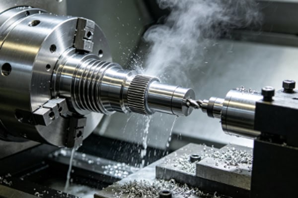
Force Distribution Between Rake Angle and Lead Angle
The combination of tool rake angle and lead angle forms the three-dimensional force layout of cutting operations, directly affecting heat dissipation conditions at the tool tip and workpiece strain deformation:
The positive or negative nature of the rake angle directly determines whether the process is “shearing” or “extruding”. Positive rake tools feature sharp cutting edges, low cutting force, and minimal heat generation, making them suitable for thin-walled parts and soft metal processing. Negative rake tools offer high edge strength and impact resistance, ideal for hard turning and interrupted cutting.
Adjusting the lead angle alters the ratio between cutting thickness and cutting width. A 93° lead angle tool generates larger axial force and smaller radial force, making it highly suitable for slender shaft turning to reduce workpiece bending deflection. Conversely, a 45° lead angle tool distributes cutting forces over a longer edge and increases heat dissipation area, significantly extending tool life. Balancing the rake angle and lead angle appropriately forms the foundation for establishing a high-rigidity cutting system.
Tool Wear Pattern Identification and Targeted Solutions
Cutting tools experience high pressure, extreme temperature, and severe friction during machining. Accurately identifying wear patterns is essential for maintaining batch manufacturing stability:
- Flank Wear: Primarily caused by friction, representing normal physical wear. Tool replacement is mandatory when the VB value reaches 0.3 mm to prevent dimensional out-of-tolerance. Regularly monitoring flank wear growth is the core measure for maintaining batch dimensional stability.
- Crater Wear: Caused by thermal diffusion creating a depression on the rake face, commonly seen in high-speed steel cutting. This can be resolved by selecting carbide or CBN tools featuring TiC or TiCN coatings. Upgrading coating materials significantly weakens chemical bonding tendencies on the rake face.
- Notch Wear: Localized damage caused by the work-hardened surface layer of the workpiece acting on the tool edge line. It is recommended to use variable depth-of-cut machining methods or alter the lead angle to disperse wear points. Breaking up localized stress points effectively prevents sudden, premature cutting edge chipping.
Establishing comprehensive tool wear evaluation criteria, complemented by automated tool life management mechanisms, effectively prevents failed tools from degrading workpiece surface integrity.
Challenging Rotary Component Turning Solutions
In shop-floor engineering practice, machining thin-walled components, slender shafts, and high-hardness materials represents a classic high-difficulty category, highly prone to vibration, thermal deformation, and out-of-tolerance dimensions.
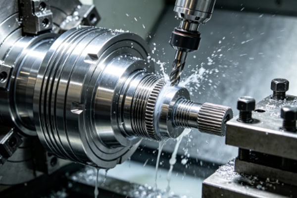
Thin-Walled Cylindrical Component Deformation Control and Fixture Innovation
Thin-walled components suffer from poor structural rigidity. Under the dual action of clamping and cutting forces, they are prone to roundness error and bell-mouth defects. Solutions must address both clamping techniques and stress release:
Applying full-circumferential pie-shaped soft jaws provides 360-degree wrapping, which drastically reduces clamping deformation compared to traditional 3-point contact standard chuck jaws. Filling the interior of the workpiece with expansion sleeves or low-melting-point alloys increases structural stiffness. Conducting stress-relief procedures between roughing and finishing, while leaving a 0.1 – 0.2 mm allowance for finishing at high cutting speeds and small feed rates, prevents heat buildup from causing geometric distorting. Systematically optimizing clamping pressure distribution and stress relief routines offers a fundamental resolution to thin-walled component deformation challenges.
Slender Shaft Machining Vibration Suppression and Follower Rest Essentials
When the length-to-diameter ratio (L/D) of a workpiece exceeds 20, it is classified as a slender shaft. Slender shafts are highly susceptible to bending vibration under cutting forces and dead weight, causing tapered or barrel-shaped dimensions:
Using a follower rest or center rest provides crucial mid-span support, maintaining rigidity at the cutting point. Adopting reverse cutting methods (where the tool feeds from the headstock toward the tailstock) keeps the workpiece under tension rather than compression, physically eliminating bucking deformation. Selecting a positive-rake insert with a 93° lead angle minimizes radial cutting forces that push the workpiece away. Multi-faceted optimization of auxiliary supports and cutting force vectors breaks through geometric limit bottlenecks in slender shaft machining.
CNC Turning Quality Defect Troubleshooting and SOP
Establishing rigorous quality monitoring and troubleshooting protocols guarantees consistent product yield rates and CPK index stability during mass production.
| Common Quality Defect | Root Cause | Process Inspection & Adjustment Strategy
|
| Dimensional Instability / Drift | Machine thermal deformation, severe tool wear, insufficient clamping force | Preheat machine tool, enable automatic tool life compensation, monitor pneumatic/hydraulic clamping pressure |
| Surface Chatter Marks | Insufficient system rigidity, excessive corner radius, spindle speed resonance | Reduce corner radius, utilize Spindle Speed Variation (SSV) to break resonance, add auxiliary rest support |
| Chip Wrapping & Surface Scratching | Mismatched chip breaker geometry, insufficient depth of cut, inadequate coolant pressure | Switch to high-efficiency chip breaker geometry, increase cut depth beyond breaker threshold, implement high-pressure coolant |
| Roundness / Concentricity Out-of-Tolerance | Chuck jaw runout, internal stress release in workpiece, spindle axial play | Re-bore soft jaws regularly, add stress-relief annealing processes, inspect and calibrate spindle runout with dial indicators |
Defining Standard Operating Procedures (SOP) effectively eliminates operator errors. Prior to operation, tool overhang must be minimized. First-article inspection requires full-dimensional coordinate measuring machine (CMM) or optical projector verification. During mass production, automatic in-process probing systems (such as Renishaw probe systems) monitor dimensional changes in real-time, executing timely tool radius and length offsets to guarantee precision consistency across the entire production lifecycle.
















