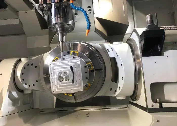
5 axis CNC milling is a subtractive manufacturing process that controls three linear axes and two rotary axes to machine complex features from multiple directions. It allows angled holes, curved surfaces, deep cavities, and several part faces to be produced with fewer setups than conventional 3-axis milling.
This guide explains how 5 axis CNC milling works, what each axis controls, how indexed and simultaneous machining differ, and when the process provides practical manufacturing value.
What Is 5-Axis CNC Milling?
5-axis CNC milling is a machining process that moves a cutting tool or workpiece along X, Y, and Z while adding two controlled rotary movements. The additional axes allow the cutter to approach the component from directions that would normally require manual repositioning or specially angled fixtures.
What Does “5-Axis” Mean?
“5-axis” means that the CNC system controls three linear movements and two rotary movements. The X-axis generally moves left to right, the Y-axis moves front to back, and the Z-axis controls vertical movement or cutting depth.
The rotary axes are selected from A, B, and C. The A-axis rotates around X, the B-axis rotates around Y, and the C-axis rotates around Z. Most 5-axis machines use either A and C or B and C rather than all three rotary axes.
The actual axis arrangement affects the machine’s usable envelope, angular range, payload, fixture clearance, and part access. Engineers should therefore evaluate the specific machine configuration instead of assuming that all 5-axis equipment can process the same geometry.
Indexed 3+2 Milling Vs Simultaneous 5-Axis Milling
Indexed 3+2 milling positions the two rotary axes before cutting and keeps them fixed while the X, Y, and Z axes machine the feature. It is suitable for compound-angle planes, multi-face pockets, angled holes, and components that require several fixed cutting directions.
Simultaneous 5-axis milling moves the linear and rotary axes together while the cutter removes material. The tool orientation can therefore change continuously as it follows a twisted blade, curved port, impeller passage, medical implant, or other freeform surface.
Indexed machining is generally easier to program, simulate, and inspect. Simultaneous machining provides greater geometric freedom, but it requires more advanced CAM control, accurate machine kinematics, verified post-processing, and detailed collision simulation.
How Does 5-Axis CNC Milling Work?
5-axis CNC milling works by converting a 3D CAD model into coordinated linear and rotary toolpaths that control both the cutter position and its orientation. The complete process includes design review, CAM programming, machine setup, workholding, simulation, cutting, and inspection.
CAD Model and Design Review
CAD model preparation defines the geometry, surfaces, holes, pockets, threads, radii, and interfaces that must be machined. The digital model should be complete and consistent with the drawing so the CAM programmer does not need to interpret missing or conflicting information.
The design review identifies thin walls, deep cavities, small internal radii, restricted undercuts, excessive tool reach, and surfaces that may cause holder or spindle interference. It also determines which features should be completed in the same setup to preserve their positional relationship.
A useful drawing should clearly define material, heat-treatment condition, datums, tolerances, surface finish, threaded features, coating requirements, and inspection expectations. A part may match the CAD shape and still fail function if these manufacturing controls are unclear.
CAM Programming and Toolpath Creation
CAM programming creates the cutting paths, tool angles, feeds, speeds, stepovers, entry moves, retracts, and rotary positions required to machine the part. 5-axis programming controls both where the tool tip moves and how the cutter is oriented relative to the surface.
Typical strategies include adaptive roughing, rest machining, indexed drilling, swarf cutting, contour milling, multi-surface finishing, flow-line machining, and localized cleanup. Each strategy should be chosen according to geometry, material behavior, tool rigidity, and the required surface condition.
The CAM output must pass through a machine-specific post-processor. The post converts calculated tool motion into CNC code that matches the controller, axis directions, pivot dimensions, travel limits, and rotary behavior of the selected 5 axis CNC machining center.
Machine Setup and Workholding
Machine setup establishes the physical relationship between the workpiece, fixture, cutting tools, spindle, probe, and machine coordinate system. Small setup errors can become more significant when the part rotates and the tool approaches it from several angles.
The workholding system must provide sufficient rigidity while exposing the required faces. Common solutions include low-profile vises, dovetail fixtures, soft jaws, modular pallets, zero-point systems, custom nests, and sacrificial bases that can be removed after the main machining operations.
Fixture clearance must be checked through the full rotary range, not only when the table is upright. A fixture may appear safe in one orientation but collide with the spindle, toolholder, rotary table, enclosure, or finished part after the axes tilt.
Multi-Axis Cutting and Tool Orientation
Multi-axis cutting controls both the cutter location and the angle at which the cutting edge contacts the workpiece. The rotary axes may position the part before machining or continue moving while the cutter follows a complex surface.
Tool orientation affects accessibility, effective cutting speed, tool engagement, surface finish, holder clearance, and rotary-axis movement. A controlled tilt can move a ball-end mill away from its low-speed center, improving cutting action and reducing rubbing on finished surfaces.
However, more rotary motion is not always better. Excessive tilting, sudden direction changes, or repeated axis reversals can increase cycle time and leave visible marks. The tool axis should move only as much as required for access, clearance, cutting performance, and surface quality.
Inspection and Quality Verification
Inspection verifies whether the 5-axis machined component meets its dimensional, geometric, and surface requirements. Owning an advanced machine does not guarantee accuracy without calibration, stable workholding, controlled tooling, temperature management, and suitable measurement methods.
In-machine probes can locate the raw stock, establish work offsets, inspect reference surfaces, and confirm intermediate dimensions before critical finishing operations. Tool setters can measure cutter length, detect broken tools, and reduce errors caused by incorrect tool data.
Final verification may use a coordinate measuring machine, optical scanner, profilometer, micrometers, bore gauges, thread gauges, or functional fixtures. The inspection method must be able to reproduce the drawing’s datum system and access the same complex features that the machine produced.
What Are the 5 Axes in CNC Milling?
The 5 axes in CNC milling are X, Y, and Z linear movements plus two rotary movements selected from A, B, and C. Together, they control both the cutter’s location and the direction from which it approaches the workpiece.
X, Y, and Z Linear Axes
X, Y, and Z move the cutter or workpiece in straight lines within the machine coordinate system. These axes establish the basic three-dimensional location of the cutting tool.
The linear axes create flat faces, pockets, holes, slots, shoulders, contours, and other standard milled features. They remain the primary cutting axes even when the machine is simultaneously rotating the table or spindle head.
Nominal X, Y, and Z travels do not always represent the maximum machinable part size. Fixtures, rotary tables, tool lengths, spindle clearance, and the rotated volume of the component can reduce the practical working envelope.
A, B, and C Rotary Axes
A, B, and C describe rotation around the X, Y, and Z directions respectively. A 5-axis machine normally combines two of these rotary movements with the three linear axes.
The rotary movement may be generated by a trunnion table, tilting rotary table, articulating spindle head, swivel head, or a combined head-table arrangement. Each design provides different advantages for compact components, heavy workpieces, deep cavities, or large structural parts.
Some rotary axes provide continuous rotation, while others have limited angular travel. The programmer must account for axis limits, cable routing, machine singularities, safe return positions, and the direction in which the table or head prefers to move.
How Do Linear and Rotary Axes Work Together?
Linear and rotary axes work together by controlling both where the cutter is and how it meets the surface. Linear movement places the cutting edge at the correct coordinate, while rotary movement establishes the required angle of approach.
This coordination allows a cutter to drill an angled hole, machine several housing faces, reach between impeller blades, or follow a curved surface without manually repositioning the workpiece.
The CNC controller must coordinate acceleration and feed across all 5 movements. Poor synchronization can cause hesitation, rotary reversals, surface witness marks, or feed variation even when the calculated toolpath looks smooth in the CAM system.
3-Axis Vs 4-Axis Vs 5-Axis CNC Milling
The main difference between 3-axis, 4-axis, and 5-axis CNC milling is the number of controlled directions available to position and orient the cutter. Additional axes increase geometric access and setup flexibility, but also increase programming, simulation, and equipment requirements.
| Milling Method | Controlled Movement | Best Fit | Main Limitation |
| 3-Axis Milling | X, Y, and Z | Plates, open pockets, brackets, panels, and accessible geometry | Requires new setups for different faces or compound angles |
| 4-Axis Milling | X, Y, Z, plus one rotary axis | Cylindrical features, radial holes, indexing, and wrapped geometry | Angled features normally need to share one rotary direction |
| 3+2 Milling | Two-axis positioning followed by 3-axis cutting | Multi-face parts, fixed compound angles, and angled holes | Rotary axes remain fixed during each cutting operation |
| Simultaneous 5-Axis Milling | Three linear and two rotary axes moving during cutting | Blades, impellers, ports, implants, and freeform surfaces | Requires advanced programming and collision control |
3-Axis CNC Milling
Three-axis CNC milling moves along X, Y, and Z while keeping the cutter orientation fixed. It is well suited to flat surfaces, open pockets, drilled patterns, plates, brackets, panels, and accessible 2.5D geometry.
Programming, workholding, and machine operation are generally simpler than multi-axis machining. Standard vises and fixtures make 3-axis milling economical for a large range of prototypes and production components.
Its main limitation appears when the part contains features on several faces or at compound angles. Each repositioning step creates additional setup labor and introduces another opportunity for datum shift, alignment error, or fixture variation.
4-Axis CNC Milling
Four-axis CNC milling adds one rotary axis to the X, Y, and Z movements. The rotary axis can index the part to fixed positions or rotate continuously during machining.
This process is effective for radial holes, cylindrical components, cam profiles, helical features, and parts that require machining around several sides. It can replace repeated manual repositioning while preserving the relationship between features around one rotational direction.
Its limitation is that angular features generally need to relate to the same rotary axis. When a component requires independent compound tilting in two directions, 3+2 or simultaneous 5-axis machining may be more efficient.
5-Axis CNC Milling
5-axis CNC milling combines three linear movements with two rotary movements to reach multi-face, angled, deep, and curved features. It may use fixed indexed orientations or continuous tool-axis control.
A suitable 5 axis CNC machining center can produce several critical surfaces without changing fixtures. This improves access and helps preserve the dimensional relationship between features located on different faces.
5-axis capability is most valuable when it replaces several difficult setups, avoids long cutting tools, or enables geometry that conventional equipment cannot reach safely. It offers little economic benefit when the component is simple and fully accessible from one direction.
5-Axis Vs 6-Axis CNC Milling
The difference between 5-axis and six-axis milling is that a six-axis system adds another independent controlled movement. This additional motion may come from a robotic structure, secondary rotary unit, or specialized spindle and table arrangement.
Six-axis machining can provide additional access to highly restricted geometry or combine milling with other operations. However, it also increases machine complexity, programming requirements, collision risk, and capital cost.
Most complex milled parts can be produced on an appropriately configured 5-axis machine. A sixth axis should be selected only when the extra motion creates a clear access, productivity, or process-integration advantage.
How to Choose the Right Number of Axes?
The right number of axes is the simplest machine configuration that can produce the component reliably and economically. Axis count should solve a manufacturing problem rather than serve as a marketing specification.
Use 3-axis milling for open and easily accessible geometry. Use 4-axis machining when several features are arranged around one rotational direction, and use 3+2 machining when fixed compound angles can eliminate special fixtures.
Use simultaneous 5-axis machining when the cutter orientation must change during material removal or when freeform surfaces, restricted access, and critical multi-face relationships cannot be managed efficiently by indexed operations.
Benefits of 5-Axis CNC Milling
The main benefits of 5-axis CNC milling are fewer setups, improved tool access, more consistent feature relationships, shorter cutting tools, complex-surface capability, and reduced handling. These advantages can improve quality and shorten the complete manufacturing route.
Fewer Setups and Improved Feature Alignment
5-axis milling reduces setups by allowing the cutter to reach several part faces from one primary fixture. Less repositioning means fewer opportunities for datum loss, alignment variation, and operator-dependent error.
Features produced in the same coordinate system can maintain better positional relationships. This is useful for bearing bores, sealing surfaces, optical mounts, threaded patterns, fluid ports, and interfaces that must align across different faces.
Setup consolidation also reduces fixture inventory, handling time, and intermediate inspection. The largest benefit often appears on low-volume complex parts, where custom angle fixtures would otherwise represent a significant percentage of the project cost.
Complex Geometry and Multi-Face Machining
5-axis milling produces complex geometry by changing the cutter’s direction of approach. Compound angles, twisted surfaces, sculpted contours, angled holes, undercuts, and several component faces can be machined within one coordinated operation.
This capability may replace special angle fixtures, form tools, separate machines, manual blending, or selected EDM operations. It also gives designers more freedom to combine functional features into a single component.
5-axis motion does not make every shape machinable. Fully enclosed cavities, extremely narrow channels, inaccessible undercuts, and features blocked by surrounding geometry may still require special tools, part splitting, EDM, additive manufacturing, or design changes.
Better Tool Access and Shorter Cutting Tools
5-axis milling improves access by tilting the tool or workpiece toward the feature. A more direct cutting angle often allows the programmer to use a shorter tool instead of extending a cutter deeply from the holder.
Shorter tools provide greater rigidity and lower deflection. This improves cutting stability, dimensional consistency, tool life, and surface finish, particularly when machining hard materials, deep walls, or thin features.
Better access may also allow a larger-diameter cutter with stronger geometry. However, the toolholder and spindle body must still be included in clearance checks because a short cutter can bring the holder closer to the workpiece.
Improved Accuracy and Surface Finish
5-axis milling can improve feature-to-feature accuracy by reducing the number of times the workpiece is repositioned. The process keeps critical surfaces within one datum structure and avoids rebuilding coordinates after every setup.
Surface finish can also improve because the cutter angle is controlled relative to the part surface. Tilting a ball-end mill away from its center improves effective cutting speed and can reduce rubbing, uneven scallops, and visible tool marks.
The machine does not automatically create tighter tolerances. Accuracy still depends on calibration, thermal stability, rotary-center compensation, fixture rigidity, tool runout, cutting parameters, material movement, and inspection capability.
Faster Production and Reduced Lead Time
5-axis milling can reduce lead time by combining operations that would otherwise require several fixtures or machines. Less manual repositioning also reduces waiting time between separate manufacturing stages.
The process can shorten the route from raw stock to inspected component, especially for prototypes and low-volume projects. It may also reduce work-in-process inventory because the part remains on one machine for more of the manufacturing sequence.
Complex programming and simulation require engineering time, so 5-axis machining is not automatically faster for every component. It delivers the greatest productivity benefit when setup savings and cutting access outweigh the added preparation.
Limitations of 5-Axis CNC Milling
The main limitations of 5-axis CNC milling are higher machine cost, more demanding programming, increased collision risk, complex maintenance, and greater dependence on skilled personnel. These factors can make it unnecessary for simple components.
Higher Machine and Programming Costs
5-axis machines generally cost more to purchase, maintain, calibrate, and operate than basic milling equipment. Their hourly rates reflect advanced rotary systems, controls, software, probing, and service requirements.
Programming also requires more engineering time because the tool axis, rotary limits, holder clearance, machine kinematics, safe retracts, and post-processor output must all be controlled.
The higher rate may still reduce total cost when the machine replaces several conventional setups. Buyers should compare the full manufacturing route rather than judging a quote by machine time alone.
More Complex CAM Programming
5-axis CAM programming is more complex because it controls tool position and orientation simultaneously. The programmer must understand both cutting strategy and the movement limits of the real machine.
Potential issues include excessive tilt, rotary-axis reversal, singularities, unstable feed, inefficient retracts, holder interference, and poor surface transitions. A visually smooth toolpath may still produce difficult machine motion after post-processing.
Program quality depends on experienced programmers, suitable CAM software, a verified post-processor, and machine simulation. These resources are especially important for simultaneous finishing of expensive or difficult-to-replace parts.
Collision and Toolpath Risks
Collision risk increases because the cutter, holder, spindle, table, fixture, raw stock, and finished component can move toward one another from changing directions.
Checking only the tool tip is not enough. Many 5-axis crashes involve the toolholder, spindle housing, table, fixture clamps, or an unmachined section of stock rather than the cutting edge.
Full-machine simulation, accurate tool assemblies, probing, safe-plane control, and conservative first-run procedures reduce risk. Simulation is valuable, but it cannot correct incorrect offsets, wrongly installed fixtures, or inaccurate tool data on the shop floor.
Skilled Operators and Process Control
5-axis machining requires experienced programmers, setup technicians, operators, and inspectors. Each role must understand how rotary motion affects work offsets, tool clearance, cutting load, and final measurement.
The operator must verify fixtures, tools, rotary range, offsets, probe results, machine condition, and initial cutting behavior. A small data-entry mistake can become serious when the table tilts toward the spindle.
Standardized setup sheets, tool lists, fixture photographs, revision control, simulation records, and first-article procedures help make the process repeatable across operators and production batches.
When Is 5-Axis Milling Not Cost-Effective?
5-axis milling is not cost-effective when the part has simple accessible geometry and does not benefit from changing tool orientation or reducing setups. A flat bracket with open pockets may be faster on a standard 3-axis mill.
It may also be unnecessary when production tooling already supports efficient multi-setup machining or when the part requires only one simple angled feature that can be produced with a basic fixture.
The correct decision should compare machine time, programming, fixtures, inspection, handling, risk, and quantity. 5-axis capability should create measurable manufacturing value rather than add avoidable complexity.
What Materials Are Suitable for 5-Axis CNC Milling?
Most machinable metals, engineering plastics, composites, graphite, and selected technical ceramics are suitable for 5-axis CNC milling. The process is defined by machine movement, while actual material compatibility depends on spindle performance, tooling, rigidity, coolant, dust control, and cutting strategy.
| Material Group | Typical Grades | Machining Characteristics | Common 5-Axis Parts |
| Aluminum | 6061, 7075, 2024, 6082 | High cutting speeds, good machinability, possible thin-wall distortion | Housings, brackets, aerospace structures, heat sinks |
| Stainless Steel | 303, 304, 316, 17-4PH | Work hardening, heat concentration, higher cutting forces | Medical tools, valve parts, industrial housings |
| Tool and Alloy Steel | D2, H13, 4140, 4340 | High forces, tool wear, heat-treatment considerations | Molds, dies, fixtures, structural parts |
| Titanium | Grade 2, Grade 5 | Low thermal conductivity, high tool wear, springback | Aerospace structures, implants, performance components |
| Nickel Alloys | Inconel, Hastelloy | Heat resistance, severe tool wear, demanding chip control | Turbine, energy, and high-temperature parts |
| Copper and Brass | C101, C110, C360 | Burr formation, adhesion, soft-material deformation | RF housings, electrodes, thermal and electrical parts |
| Engineering Plastics | PEEK, POM, Nylon, PC, PTFE | Heat sensitivity, clamping deformation, moisture movement | Medical, automation, electronic, and insulating components |
| Composites | CFRP, GFRP, FR4, G10 | Abrasive fibers, delamination, dust generation | Aerospace panels, electronic fixtures, structural parts |
| Specialty Materials | Graphite, machinable ceramics | Abrasive dust, brittleness, edge-chipping risk | Electrodes, semiconductor and technical components |
Aluminum and Aluminum Alloys
Aluminum alloys are highly suitable for 5-axis milling because they generally combine good machinability with low density and useful mechanical strength. They are widely used for housings, structural brackets, heat-management parts, prototypes, and aerospace components.
The material supports high cutting speeds, but large pockets and thin walls can still distort as internal stress is released. Balanced roughing, controlled stock allowance, stable fixturing, and finishing after the part has relaxed can improve dimensional consistency.
Grade selection affects strength, corrosion resistance, finishing, and cost. For example, a higher-strength alloy may improve performance but increase material cost or reduce anodizing consistency, so the application should determine the grade rather than machining convenience alone.
Stainless Steel and Tool Steel
Stainless steel and tool steel are suitable for 5-axis milling when the machine, tooling, and workholding provide sufficient rigidity. These materials are used for medical instruments, molds, dies, valves, industrial components, and wear-resistant parts.
Stainless steels can work-harden if the cutter rubs instead of cutting, while tool steels may generate high forces and tool wear. Stable engagement, sharp tooling, controlled heat, and suitable coolant delivery are important for maintaining dimensional and surface quality.
The heat-treatment condition should be confirmed before programming. Machining in the hardened state may reduce post-treatment distortion but increases tool cost and cycle time, while machining before heat treatment may require stock allowance for later finishing.
Titanium and Nickel Alloys
Titanium and nickel alloys can be 5-axis milled, but they require controlled cutting loads, heat management, rigid tools, and careful tool-life planning. They are commonly selected for aerospace, medical, energy, and high-temperature applications.
Titanium has low thermal conductivity, so much of the cutting heat remains near the tool edge. Nickel alloys also resist deformation at elevated temperatures, increasing cutting force and accelerating wear during long finishing paths.
5-axis orientation can improve access and support shorter cutters, but aggressive motion does not solve material-related difficulties. Stable engagement, conservative radial depth, suitable coatings, coolant delivery, and planned tool replacement are essential for valuable parts.
Copper and Brass
Copper and brass are suitable for 5-axis milling when sharp tools, stable clamping, and effective chip evacuation are used. Common applications include electrodes, RF housings, electrical contacts, thermal components, and precision connectors.
Pure copper can be soft and adhesive, which may cause burrs, built-up edge, or smearing. Free-machining brass usually produces shorter chips and more predictable surfaces, although alloy composition should be checked when regulatory or electrical requirements apply.
Because many copper components contain thin walls or small thermal features, excessive clamping can deform the workpiece. The fixture should provide enough support without marking or compressing functional surfaces.
Engineering Plastics
Engineering plastics are suitable for 5-axis milling when heat, clamping force, tool sharpness, and material stability are controlled. PEEK, POM, nylon, polycarbonate, PTFE, and other polymers are used in medical, electronic, automation, and industrial applications.
Plastics generally require sharp cutters and light cutting forces because heat can soften the surface, create burrs, or change dimensions. Some materials absorb moisture, while others move after internal stress is released during heavy stock removal.
Inspection conditions are also important. A plastic part measured immediately after warm machining may not represent its stable dimensions, so cooling time and controlled measurement temperature should be considered for tight-tolerance features.
Composites and Machinable Ceramics
Composites and machinable ceramics can be processed on 5-axis equipment, but they require specialized tools and environmental controls. Their main challenges are abrasion, brittleness, delamination, fiber pull-out, and dust.
Carbon-fiber and glass-fiber composites can quickly wear conventional carbide edges. Tool geometry, cutting direction, backing support, and dust extraction must be selected to protect the laminate and maintain clean edges.
Machinable ceramics and graphite may require diamond-coated tools, low-vibration cutting, and dedicated extraction. The process should also prevent abrasive dust from contaminating machine components or nearby metal-machining operations.
What Parts Can Be Made With 5-Axis CNC Milling?
5-axis CNC milling can produce complex multi-face, curved, angled, and deep-cavity components that are difficult to complete with conventional setups. Suitable parts range from small medical devices to large structural components, depending on machine size and configuration.
Multi-Face Housings and Brackets
5-axis milling can produce housings and brackets with pockets, holes, bores, mounting faces, and interfaces on several sides. These parts are common in aerospace, electronics, robotics, automation, and industrial equipment.
Machining several faces in one setup helps preserve the relationship between bearing seats, connector locations, sealing faces, threaded holes, and reference datums. This reduces the risk created by repeatedly rebuilding coordinates.
The main design concerns are fixture access, wall support, toolholder clearance, and distortion after large amounts of stock are removed. A stable sacrificial base or dovetail feature can simplify workholding and final separation.
Impellers and Turbine Blades
5-axis milling is well suited to impellers and turbine blades because their curved surfaces and restricted passages require changing tool orientation. The cutter must reach between blades while avoiding adjacent geometry.
Roughing usually leaves controlled stock around the blade and hub, followed by semi-finishing and finishing paths that gradually release cutting stress. Tool-axis control is used to maintain clearance and stable contact along the aerodynamic profile.
Inspection may require scanning, profile comparison, or CMM measurement because conventional hand tools cannot fully verify twisted surfaces. Tool wear must also be monitored because small profile changes can affect part performance.
Complex Curved and Contoured Parts
5-axis milling can produce complex contours such as molds, orthopedic components, aerodynamic surfaces, optical mounts, and sculpted product geometry. Simultaneous movement allows the cutter to follow both concave and convex surfaces.
Surface quality depends on cutter shape, stepover, tool orientation, machine dynamics, and the continuity of the programmed path. Abrupt direction changes can leave witness marks even when the nominal geometry is correct.
The required surface finish should be defined only where function demands it. Very fine scallop control across large cosmetic or freeform surfaces can add substantial cycle time without improving the part’s mechanical performance.
Deep-Cavity and Angled-Feature Parts
5-axis milling can process deep cavities, angled ports, compound bores, side holes, and recessed surfaces by orienting the workpiece toward the cutter. This reduces dependence on long-reach tooling and special fixtures.
Direct tool access improves rigidity and chip evacuation, but the cutter and holder still need sufficient space. Narrow openings, sharp internal corners, and deep enclosed regions can remain difficult even on advanced equipment.
Designers should use practical cavity widths, internal radii, and approach angles. A feature that is technically reachable may still be expensive if it requires a small tool, slow cutting, repeated retracts, or specialized inspection.
Medical Implants and Precision Instruments
5-axis milling can produce medical implants, dental components, prosthetic parts, surgical instruments, and precision device hardware. These components often combine organic contours with controlled interfaces and small functional features.
The process can follow patient-specific or anatomical geometry while maintaining holes, mating surfaces, and fixation features. Materials may include titanium, stainless steel, cobalt-based alloys, or high-performance plastics.
Manufacturing requirements extend beyond geometry. Material traceability, controlled finishing, burr removal, cleaning, inspection documentation, and process validation may be necessary depending on the device and regulatory environment.
Custom Complex Prototypes
5-axis milling can produce custom prototypes directly from solid material without dedicated molds or casting dies. It is useful for testing designs that contain curved surfaces, angled interfaces, and several machined faces.
The prototype can be made from a material close to the intended production grade, allowing more meaningful functional, thermal, and mechanical testing than a visual model.
For early designs, unnecessary tight tolerances and cosmetic finishes should be avoided. Prototype machining should focus on validating function, assembly, and geometry before expensive details are locked into production.
Common Applications of 5-Axis CNC Milling
5-axis CNC milling is used in industries where components require complex geometry, difficult materials, precise feature relationships, or fewer setups. Common sectors include automotive, industrial equipment, medical, aerospace, automation, electronics, robotics, defense, and energy.
Automotive
Automotive applications include cylinder heads, intake ports, transmission housings, suspension components, battery structures, molds, and motorsport prototypes. These parts often contain multi-face mounting features and complex flow surfaces.
5-axis machining reduces fixture changes while providing access to angled ports and contoured regions. The main risks include thin-wall distortion, large stock removal, and maintaining alignment between bearing, sealing, and mounting features.
Industrial Equipment
Industrial-equipment applications include valve bodies, pump housings, compressor components, manifolds, impellers, tooling, and custom machine parts. Many combine ports, sealing faces, bores, and mounting features in one component.
5-axis access helps consolidate these operations, but heavy parts may require machines with sufficient rotary-table payload and torque. Fixture design must support the component without blocking flow passages or inspection surfaces.
Medical
Medical applications include orthopedic implants, dental components, surgical instruments, prosthetic hardware, and diagnostic-device parts. The geometry may combine organic contours with very small holes, slots, or mating features.
5-axis machining provides access and surface continuity, while the manufacturing plan must also control burrs, contamination, traceability, and inspection. The supplier’s documentation and finishing capability may be as important as the machine itself.
Aerospace
Aerospace applications include turbine blades, impellers, structural brackets, bulkheads, housings, engine parts, and aerodynamic surfaces. These components often use aluminum, titanium, stainless steel, or nickel-based alloys.
5-axis machining supports thin walls, deep pockets, curved profiles, and weight-reduction geometry. Process planning must manage distortion, tool wear, profile accuracy, material certification, and detailed dimensional reporting.
Automation
Automation applications include gripper bodies, end-of-arm tooling, sensor mounts, fixtures, positioning devices, and custom production hardware. These parts frequently integrate several functions into a compact structure.
5-axis milling can reduce the number of assembled components by combining interfaces, air passages, mounting angles, and weight-reduction pockets. The finished part must still provide stable datums and repeatable interfaces for assembly.
Electronics
Electronics applications include RF housings, heat sinks, optical mounts, connector bodies, test fixtures, precision chassis, and thermal-management components. Compact designs may contain angled features and pockets on several faces.
5-axis access is useful for maintaining the relationship between connector openings, sealing faces, thermal interfaces, and mounting holes. Burr control, cosmetic surfaces, conductivity, and coating allowance often influence the process plan.
Robotics
Robotics applications include joint housings, actuator parts, structural links, lightweight arms, grippers, and sensor supports. These components often combine weight reduction with accurate bearing and motor interfaces.
5-axis machining can create curved lightweight structures while preserving critical bores and mounting surfaces. The main challenges are deformation of thin sections and maintaining stiffness after large amounts of material are removed.
Aerospace and Defense
Aerospace and defense applications include propulsion, sensing, optical, communication, guidance, and structural components. Projects may involve difficult materials, controlled profiles, and complex multi-face geometry.
Beyond machining, the supplier may need to manage traceability, controlled documentation, special inspection, export requirements, and secure handling of project information.
Oil and Gas
Oil and gas applications include downhole tools, valve bodies, flow-control components, manifolds, pump parts, and sealing hardware. These parts may contain compound bores, angled passages, and corrosion-resistant alloys.
5-axis access can reduce setups and improve relationships between flow paths and sealing surfaces. Hard materials, deep holes, pressure-related geometry, and difficult inspection conditions must be considered during design review.
Design Guidelines for 5-Axis CNC Milling
Good 5-axis design provides clear datums, practical tolerances, sufficient tool access, stable walls, usable corner radii, and adequate fixture clearance. 5-axis capability should solve functional problems rather than justify unnecessary geometry.

Define Functional Tolerances and Datums
Functional tolerances and datums should describe how the component fits, aligns, seals, or moves in assembly. They should focus process control on features that directly affect performance.
Multi-face features should reference a stable datum system that can be established in the fixture and reproduced during inspection. Poor datum selection can make a reasonable tolerance difficult to machine or impossible to measure consistently.
Avoid applying tight tolerances to every dimension. Unnecessary control increases finishing passes, inspection time, tool-change frequency, environmental requirements, and scrap risk without improving function.
Improve Tool Access and Cutting Angles
Tool access should allow both the cutting edge and toolholder to reach the surface without interference. 5-axis movement improves approach direction but cannot pass a solid holder through surrounding geometry.
Open access paths, reasonable gaps, and practical tilt angles allow shorter tools and stronger holders. These choices improve rigidity and make the process less sensitive to chatter and deflection.
Designers should consider the complete tool assembly rather than the cutter diameter alone. A narrow feature may accept the cutting tool while still preventing the holder or spindle from reaching the required depth.
Avoid Excessively Deep Cavities
Excessively deep cavities increase tool overhang, vibration, chip accumulation, and machining time. 5-axis tilting can improve access, but it does not remove all depth-related limitations.
Where possible, reduce cavity depth, increase the opening width, use stepped regions, or split the component into machinable sections. Larger access openings may also improve cleaning, coating, and inspection after machining.
A deep cavity should be justified by function. If the depth only removes weight or creates an invisible cosmetic feature, a simpler pocket may provide similar performance at lower cost.
Use Practical Internal Corner Radii
Practical internal corner radii allow standard end mills to maintain smooth motion and stable cutting engagement. An internal corner cannot be perfectly sharp when it is produced by a rotating cylindrical cutter.
A radius larger than the tool radius prevents the cutter from becoming fully engaged in the corner. This reduces cutting-force spikes, chatter, heat, and visible marks.
Very small radii require small-diameter tools, which are less rigid and remove material slowly. Increasing a noncritical radius can reduce cycle time and tool risk without changing the component’s function.
Control Thin Walls and Unsupported Features
Thin walls should be thick and supported enough to resist cutting force, clamping pressure, and material stress. Tall or uneven walls may bend during machining and move again after the fixture is released.
Balanced roughing, alternating cuts, light finishing passes, temporary support ribs, and carefully placed clamps can reduce distortion. However, process control cannot fully compensate for an extremely weak design.
Wall thickness should be selected according to material, height, length, tolerance, and surface finish. A thin aluminum wall may behave very differently from a similarly sized stainless-steel or plastic feature.
Plan Workholding and Fixture Clearance
Workholding should be considered before the final geometry is frozen. The manufacturer needs rigid surfaces or temporary features that can be clamped without damaging functional areas.
Sacrificial tabs, dovetail bases, removable stock, custom soft jaws, or zero-point fixtures can improve access and repeatability. These features should provide support while leaving the important faces exposed.
The rotated volume of the complete part and fixture must remain inside the machine envelope. Clearance should also be available for probing, tool changes, chip evacuation, and safe retract movements.
Simplify Non-Functional Complexity
Non-functional complexity should be removed when it does not improve performance, assembly, weight, or appearance. Every compound angle, small radius, decorative pocket, or freeform surface adds programming and machining effort.
Simplification may allow larger tools, smoother toolpaths, fewer orientations, easier inspection, and lower scrap risk. It can also make future design revisions less expensive.
A DFM review should identify which features truly require 5-axis capability and which can be replaced with simpler geometry. This helps preserve engineering intent without paying for unnecessary machine motion.
How to Optimize the 5-Axis Milling Process?
The 5-axis milling process is optimized by using rigid tools, stable engagement, controlled tool orientation, verified simulation, and planned management of heat, wear, and distortion. Optimization should improve repeatability, not only shorten the programmed cycle.
Select Suitable Cutting Tools
Suitable cutting tools match the material, feature size, required reach, surface condition, and cutting strategy. Short tools should be used whenever the geometry allows because they provide better rigidity.
Tool material, coating, flute count, helix angle, edge preparation, and holder type affect chip formation, heat, cutting force, and tool life. A tool optimized for aluminum may perform poorly in titanium or abrasive composites.
Long-reach and small-diameter tools should be reserved for features that genuinely require them. When such tools are unavoidable, cutting loads, runout, holder balance, and replacement intervals should be controlled carefully.
Optimize Toolpaths and Tool Orientation
Optimized toolpaths maintain stable cutter engagement and avoid unnecessary rotary movement. The tool angle should provide access and clearance without causing abrupt axis changes.
Smooth linking moves, controlled lead and tilt angles, consistent cutting direction, and gradual transitions improve machine behavior. They can also reduce witness marks where adjacent finishing paths meet.
The programmer should review actual axis movement rather than only the contact point on the model. A small change at the tool tip may require a large or fast rotary movement when the cutter is far from the machine’s pivot center.
Use Collision Detection and Machine Simulation
Collision detection should include the cutter, holder, spindle, table, fixture, stock, finished part, and machine enclosure. Checking the cutting edge alone does not represent real shop-floor risk.
Machine simulation should use the correct rotary configuration, travel limits, pivot data, and tool assemblies. Generic simulation may approve a path that the actual machine cannot reach safely.
A verified simulation reduces prove-out time, but the first production run should still use cautious feed control, offset checks, probing, and observation. Digital verification cannot detect a fixture installed in the wrong orientation.
Control Feed Rate, Spindle Speed, and Tool Engagement
Feed rate, spindle speed, and cutter engagement should match the material, tool geometry, machine rigidity, and intended operation. Stable chip thickness is more important than using the highest available speed.
Constant-engagement roughing helps avoid sudden force increases in corners and narrow regions. Finishing parameters should control scallop height, cutting direction, heat, and edge quality rather than simply reducing feed.
Rotary movement can affect tool-tip feed even when individual axes appear to move slowly. Advanced controllers and CAM systems may compensate for this, but the programmer should still review the resulting motion and surface.
Manage Tool Wear, Heat, and Part Distortion
Tool wear, heat, and distortion should be managed before they affect dimensions or surface finish. 5-axis programs often contain long finishing cycles where gradual tool deterioration can change the final profile.
Machine warm-up, stable coolant temperature, planned tool replacement, tool-life monitoring, and in-process probing can improve consistency. High-value parts should not rely on the cutter lasting until visible failure.
Part distortion should be managed through balanced stock removal, roughing on multiple sides, controlled clamping, stress-relieved material, and finishing after the component has stabilized.
Surface Treatments for 5-Axis Milled Parts
Common surface treatments for 5-axis milled parts include anodizing, electroplating, powder coating, heat treatment, polishing, and bead blasting. The correct treatment depends on material, corrosion resistance, hardness, conductivity, appearance, and dimensional requirements.

| Surface Treatment | Typical Materials | Main Purpose | Manufacturing Consideration |
| Anodizing | Aluminum | Corrosion resistance, hardness, appearance | Coating affects dimensions and color may vary by alloy |
| Electroplating | Steel, copper, brass, selected alloys | Corrosion, conductivity, wear, appearance | Threads and tight fits may need masking |
| Powder Coating | Aluminum and steel | Durable protective and cosmetic finish | Thick coating can fill small features |
| Heat Treatment | Steel, aluminum, titanium alloys | Strength, hardness, stress control | Distortion may require finish machining |
| Polishing | Metals and selected plastics | Smoothness and cosmetic appearance | Can round edges or alter small details |
| Bead Blasting | Aluminum, stainless steel, other metals | Uniform matte texture | Handling and masking affect cosmetic consistency |
Anodizing
Anodizing is an electrochemical treatment mainly used to improve the corrosion resistance, surface hardness, and appearance of aluminum components. It can also provide decorative color.
The coating changes the final dimensions of treated surfaces, which matters for bores, threads, sealing faces, and tight fits. The drawing should clarify whether dimensions apply before or after anodizing.
Alloy and surface condition influence color and consistency. Parts intended to match cosmetically should use controlled material batches and consistent machining and blasting procedures.
Electroplating
Electroplating deposits a metallic layer such as nickel, zinc, chrome, or another coating onto the component. It is used for corrosion protection, conductivity, wear resistance, or appearance.
Plating thickness can affect small holes, threads, fits, and sharp edges. Functional areas may require masking, and the coating specification should define both material and required thickness.
Complex 5-axis geometry may create coating-distribution challenges in recesses and deep cavities. The finishing supplier should review whether the geometry can receive uniform coverage.
Powder Coating
Powder coating provides a durable protective and cosmetic finish on aluminum, steel, and other suitable metals. It is commonly used for housings, brackets, frames, and exposed equipment components.
The coating is thicker than most plating or anodizing layers. Small holes, threads, grounding points, sealing interfaces, and precision mating surfaces normally require masking.
Sharp edges may receive less uniform coverage than broad surfaces, while deep pockets can be difficult to coat evenly. Edge design and hanging orientation should be reviewed before production.
Heat Treatment
Heat treatment changes the mechanical properties, hardness, strength, or internal stress of metal parts. It may be applied before roughing, between machining stages, or after the main material removal.
The sequence affects dimensional stability. Machining after hardening increases tool wear, while heat treatment after machining can distort bores, flatness, position, and thin walls.
Critical components may require rough machining, stress relief, heat treatment, and final finishing. The drawing and purchase requirements should clearly define the required condition.
Polishing and Bead Blasting
Polishing and bead blasting modify the surface texture and appearance of machined parts. Polishing reduces roughness or creates a reflective surface, while bead blasting produces a more uniform matte finish.
Manual polishing can round sharp edges, soften small details, and change local dimensions. Cosmetic requirements should therefore identify controlled surfaces and acceptable directional marks.
Bead blasting can hide minor toolpath variation but will not remove deep cutter marks or geometry errors. Parts should be machined to an appropriate baseline finish before cosmetic processing.
What Affects 5-Axis CNC Milling Cost?
5-axis CNC milling cost is affected by material, stock size, geometry, tolerance, surface finish, programming, setup, tooling, inspection, production quantity, and lead time. The machine’s hourly rate is only one part of the complete cost.
Material and Stock Size
Material affects cost through purchase price, cutting speed, tool wear, coolant requirements, and machining difficulty. Titanium and nickel alloys generally require more time and tooling than aluminum or free-machining brass.
Stock size determines how much material must be removed. A lightweight finished component may still be expensive when it begins as a large billet and requires extensive roughing.
Near-net stock, forgings, or castings can reduce waste for suitable production quantities. However, they may add tooling, minimum-order, or lead-time requirements that are not economical for prototypes.
Part Geometry and Material Removal
Complex geometry increases cost when it requires restricted access, many tools, small stepovers, slow finishing, or repeated tool-axis changes. Deep cavities and thin walls also increase risk.
Large material-removal ratios add roughing time, chip volume, tool wear, and distortion control. The process may need staged roughing or intermediate relaxation before finishing.
Removing non-functional complexity is often the most effective way to reduce cost. A small design change can enable a larger cutter, shorter tool, simpler fixture, or faster inspection.
Tolerances and Surface Finish
Tighter tolerances increase cost because they require more stable conditions, finishing passes, tool monitoring, probing, and inspection. They may also increase scrap risk.
Fine surface finishes require smaller stepovers, controlled cutting directions, more passes, and sometimes manual polishing. Large freeform areas can consume substantial machine time.
Only functional surfaces should receive demanding controls. General tolerances and standard machined finishes are usually sufficient for noncritical regions.
Programming and Setup Complexity
Programming cost increases with simultaneous motion, many machining orientations, collision-sensitive features, and complex surface finishing. The CAM engineer must also verify the post-processed machine movement.
Setup cost includes stock preparation, fixture design, soft jaws, probing routines, tool preparation, and first-part prove-out.
Repeat orders distribute these fixed engineering costs across more components. Stable revisions and reusable fixtures therefore improve unit economics.
Tooling and Fixture Requirements
Tooling cost depends on cutter material, coating, size, reach, holder, and expected life. Hard alloys, abrasive composites, and small finishing tools may require frequent replacement.
Custom fixtures cost more than standard vises, but they may improve access, repeatability, and cycle time. A well-designed fixture can also reduce inspection variation.
For prototypes, simple sacrificial workholding may be more economical than a dedicated fixture. Production quantities may justify zero-point or multi-part systems that reduce setup time.
Production Quantity and Lead Time
Production quantity affects how programming, setup, tooling, and inspection costs are distributed. 5-axis milling can be economical for prototypes because it avoids dedicated molds and angle fixtures.
For repeat production, optimized fixtures, proven programs, and controlled tool-life data can reduce unit cost. Batch size should also consider work-in-process, inspection capacity, and material availability.
Compressed lead times may increase cost when they require priority scheduling, expedited materials, rapid tool procurement, overtime, or interrupted production plans.
How to Choose a 5-Axis CNC Milling Service Provider?
A 5-axis CNC milling supplier should be selected according to machine capability, programming experience, material knowledge, inspection resources, quality systems, communication, and production support. Ownership of a 5-axis machine alone does not prove manufacturing competence.
Machine Size and Axis Configuration
The machine size and axis configuration must match the component’s dimensions, weight, rotary clearance, and spindle requirements. Nominal travel alone does not confirm that the part can rotate safely.
A 5 axis CNC vertical machining center may be effective for compact precision components, while larger head-table or head-head equipment may be better for heavy structures and long parts.
The supplier should evaluate the complete rotated envelope, fixture height, spindle clearance, tool reach, and rotary payload before confirming manufacturability.
Material and Industry Experience
Material experience helps the supplier select appropriate tools, cutting parameters, coolant, fixtures, and distortion-control methods. 5-axis movement does not replace knowledge of difficult material behavior.
Industry experience is important when the project requires traceability, certification, controlled finishing, regulated documentation, or specialized inspection.
Comparable component examples are more useful than broad capability statements. The supplier should be able to explain the risks and manufacturing route for the specific geometry and material.
CAM Programming and Simulation Capability
The supplier should use suitable CAM software, machine-specific post-processors, and full collision simulation. These systems convert the design into safe and controllable machine movement.
Ask whether the simulation includes the actual spindle, rotary table, fixtures, toolholders, stock, and travel limits. Tool-tip simulation alone is not enough for complex 5-axis work.
A mature programming process includes revision control, documented tool assemblies, controlled prove-out, and verification of the posted CNC code rather than relying only on the original CAM model.
Tolerance and Inspection Capability
Tolerance capability should be supported by calibrated measurement equipment and methods that can access the component’s complex features. A general tolerance claim is not sufficient.
Angled holes, freeform profiles, multi-face position, and compound datums may require CMM inspection, optical scanning, or custom fixtures.
The supplier should explain how the drawing datum system will be established during both machining and inspection. A feature cannot be controlled reliably when the measurement method does not reproduce the intended reference structure.
Quality Assurance and Certification
Quality assurance should control material identification, drawing revision, setup, tooling, inspection, nonconformance, finishing, and shipping. Certification supports the system but does not replace daily process discipline.
Inspection records, first-article reports, material certificates, and process documentation should be available when the project requires them.
The appropriate quality level depends on application risk. A visual prototype may need basic dimensional verification, while an aerospace, medical, or pressure component may require detailed traceability.
Lead Time, Communication, and Production Support
Reliable production support includes clear DFM feedback, realistic scheduling, responsive engineering communication, and controlled design revisions.
A qualified provider of 5 axis CNC machining services should identify inaccessible geometry, unnecessary tolerances, distortion risks, coating allowances, and cost-saving opportunities before machining begins.
For repeat production, the supplier should retain controlled programs, fixture information, inspection plans, tool data, and manufacturing history. This supports consistent quality when the component is reordered.
FAQs
What Is The Difference Between 3-Axis, 4-Axis, And 5-Axis CNC Mills?
A 3-axis CNC mill moves along X, Y, and Z and mainly machines features from one direction. A 4-axis mill adds one rotary axis for cylindrical or multi-side parts. A 5-axis mill adds two rotary axes, allowing compound angles and several faces to be machined in one setup. This reduces fixture changes, alignment errors, and total processing time for complex components.
Is 5-Axis CNC Machining Faster?
5-axis CNC machining is often faster for complex parts because it can combine three to five conventional setups into one primary setup. It reduces repositioning, fixture changes, alignment, and intermediate inspection. However, CAM programming and collision simulation usually take longer. For simple plates or open pockets, a 3-axis machine may still provide a shorter cycle and lower overall cost.
What Is The Difference Between 5-Axis And 6-Axis CNC Machining?
A 5-axis CNC machine uses three linear axes and two rotary axes to machine most complex multi-face and contoured parts. A 6-axis machine adds one more controlled movement, providing greater access to restricted geometry or supporting combined milling and turning operations. The additional axis increases flexibility, but it also raises equipment cost, programming difficulty, collision risk, and process-verification requirements.
Conclusion
5-axis CNC milling combines three linear movements with two rotary movements to manufacture complex, multi-face, angled, and contoured components. Its main value comes from reducing setups, improving tool access, maintaining feature relationships, using shorter cutters, and supporting high-quality surfaces. Successful results still depend on practical design, verified CAM programming, stable workholding, collision simulation, controlled tooling, and suitable inspection.
At TiRapid, we provide precision CNC machining and manufacturing services for custom metal and plastic components. Our capabilities support prototypes and low-volume parts requiring multi-axis milling, complex geometry, controlled tolerances, material review, DFM feedback, dimensional inspection, surface finishing, and reliable production support.