3+2 vs 5 axis machining is often misunderstood because both processes use CNC machines with three linear axes and two rotary axes. However, the way those axes move during cutting is different. This difference affects the parts each process can produce, the required programming work, surface quality, machining time, setup risk, and final manufacturing cost.
This guide explains how 3+2 and simultaneous 5-axis machining work, their main capability and cost differences, and the parts best suited to each method. It also shows how engineers and buyers can compare geometry, tolerance, surface finish, lead time, and budget before selecting a machining process.
What Are 3+2 And Simultaneous 5-Axis Machining?
Both processes use three linear axes, normally X, Y, and Z, together with two rotary axes. Depending on the machine configuration, the rotary movement may come from a tilting table, a rotating table, a tilting spindle head, or a combination of the table and spindle.
The main distinction is whether the rotary axes move during cutting. In 3+2 machining, they position the part or tool and then remain fixed. In simultaneous 5-axis machining, the rotary and linear axes can move together while the tool remains engaged with the workpiece.
How 3+2 Axis Machining Works?
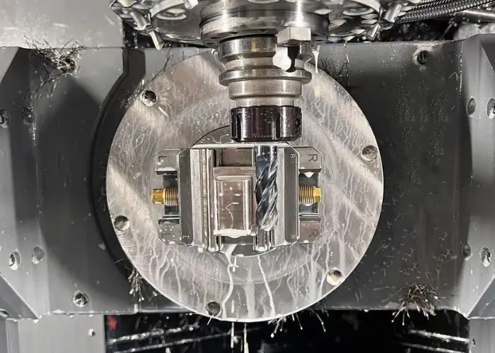
3+2 axis machining is also called positional 5-axis, indexed 5-axis, or 5-sided machining. The machine uses its two rotary axes to place the workpiece at a selected angle. Once the position is reached, the rotary axes are locked, and the machine completes a conventional 3-axis toolpath.
After one feature or face is finished, the tool retracts and the machine indexes to another position. The next drilling, milling, pocketing, or finishing operation is then completed from the new fixed angle. This allows several sides of a component to be machined in one setup.
Because the cutting stage still uses stable 3-axis movement, 3+2 programming is relatively straightforward. Standard drilling cycles, pocketing strategies, contouring operations, and conventional cutting tools can often be applied from multiple work planes.
This process is well suited to angled holes, inclined faces, multi-side pockets, counterbores, threaded features, and parts that would otherwise require several fixtures on a 3-axis machine. It reduces manual repositioning without adding unnecessary continuous rotary movement.
How Simultaneous 5-Axis Machining Works?
In simultaneous 5-axis machining, all three linear axes and both rotary axes can move together during the cutting operation. The CNC control continuously calculates the tool position and orientation so the cutting edge follows the required three-dimensional surface.
Continuous movement allows the tool to maintain a suitable contact angle while following curved, twisted, tapered, or undercut geometry. Instead of machining a complex surface from several fixed directions, the tool orientation changes smoothly along the programmed path.
This capability is especially valuable for freeform surfaces, impellers, turbine blades, medical implants, aerospace structures, deep molds, and parts with continuously changing wall angles. It can also improve access to difficult areas while allowing shorter and more rigid cutting tools.
However, simultaneous motion places greater demands on the CAM software, post processor, machine calibration, control system, and programmer. The tool, holder, spindle, fixture, rotary table, and workpiece must all be included in reliable collision simulation.
3+2 vs 5 Axis: Key Capability Differences
The correct process depends less on the number of machine axes and more on how the part geometry uses them. Many complex-looking components can be produced efficiently with fixed-angle 3+2 toolpaths, while others require continuous tool orientation throughout the cut.
| Comparison | 3+2 Axis Machining | Simultaneous 5-Axis Machining |
| Rotary-axis movement | Positions and locks before cutting | Moves continuously during cutting |
| Cutting motion | Mainly 3-axis from fixed angles | Coordinated 5-axis movement |
| Best geometry | Multi-face and angled features | Freeform and continuously curved surfaces |
| Programming difficulty | Moderate | High |
| Collision risk | Lower after indexing | Higher during continuous movement |
| Tool orientation | Fixed for each operation | Continuously adjustable |
| Surface blending | May require several tool directions | Smoother across complex contours |
| Typical cost | Lower | Higher |
| Setup reduction | Strong | Strong |
| Main value | Efficient multi-side access | Maximum geometric flexibility |
Axis Movement And Tool Orientation
In 3+2 machining, the tool axis remains fixed during each cutting operation. A programmer selects the best angle for one group of features, machines them, and then indexes to the next angle. Each position acts like a temporary 3-axis coordinate system.
This fixed orientation provides predictable cutting conditions. The rotary axes are normally clamped during material removal, which can improve stability when roughing pockets, drilling holes, or machining flat and angled surfaces.
Simultaneous 5-axis machining adjusts the tool direction while the toolpath is running. This allows the side, tip, or flank of the cutter to remain in a controlled relationship with the workpiece surface.
The additional freedom can improve cutting contact and avoid tool-holder interference. However, unnecessary rotary motion can increase cycle time, create less stable machine movement, or make the program harder to verify. Full 5-axis motion should therefore be used where the geometry creates a real need.
Part Geometry And Feature Accessibility
3+2 machining is highly effective when a part contains several features on different faces but each feature can be machined from a fixed direction. Examples include housings with side holes, brackets with angled mounting faces, manifolds with intersecting ports, and fixtures with features on five sides.
The machine can reach these areas without removing and manually repositioning the part. Reducing setups helps preserve the relationship between features because they remain tied to the same fixture and machining datum.
Simultaneous 5-axis is more suitable when the required tool angle changes continuously. Turbine blades, impellers, orthopedic components, sculpted molds, and aerodynamic surfaces often cannot be divided into a small number of fixed machining planes without leaving steps, inaccessible areas, or poor tool contact.
Undercuts also require careful evaluation. Some undercuts can be reached by indexing the workpiece to a suitable 3+2 angle. Others contain continuously changing geometry that requires simultaneous motion or specialized tools.
Accuracy, Tool Rigidity, And Surface Finish
Both methods can produce accurate parts when the machine, fixture, program, tooling, and inspection plan are properly controlled. The assumption that simultaneous 5-axis is always more accurate is incorrect. Accuracy depends on the complete manufacturing system rather than axis count alone.
3+2 machining can provide excellent accuracy for holes, flat faces, pockets, and angled features. Because the rotary axes remain locked during cutting, the process can offer stable positioning and predictable tool engagement.
Using one setup also reduces errors caused by repeatedly removing and locating the workpiece. Features machined from different indexed angles can maintain a stronger positional relationship than the same features produced through several separate 3-axis setups.
Simultaneous 5-axis can improve accuracy and surface finish on continuous contours because the tool follows the geometry without repeated repositioning or manual blending. It can also use shorter cutters by tilting the tool away from walls and fixtures, which reduces deflection and vibration.
Surface quality still depends on rotary-axis smoothness, machine calibration, toolpath spacing, feed control, cutter geometry, and the location of the part relative to the machine’s center of rotation. Poorly optimized 5-axis movement can leave marks even when the programmed surface is mathematically correct.
Programming, Simulation, And Collision Control
3+2 programming is generally easier because each indexed position uses familiar 3-axis strategies. The programmer defines a tool orientation or work plane, selects suitable machining operations, and verifies the indexing movement between positions.
Although simpler, 3+2 machining still requires collision checking. The tool may be safe during cutting but collide with the fixture, table, or workpiece while the rotary axes are indexing. Clearance must be checked before every orientation change.
Simultaneous 5-axis programming requires continuous control of the tool axis. The CAM system must calculate how the cutter approaches the surface while controlling lead, lag, tilt, contact point, machine limits, and collision avoidance.
Reliable simulation should represent the real machine configuration, including the spindle, rotary axes, table, fixture, stock, tool holder, and cutter. A toolpath that looks safe when only the tool tip is displayed may still cause a holder or machine collision.
The post processor is equally important. It converts CAM toolpaths into machine-specific code and must match the actual kinematics and control functions. An incorrect post processor can create unexpected rotary movement even when the CAM simulation appears correct.
3+2 vs 5 Axis Machining Cost
Cost differences come from more than the machine’s hourly rate. Programming time, fixture design, setup complexity, cutting tools, simulation, cycle time, inspection, and production risk all affect the final price.
A more advanced process is not automatically more expensive for every part. Simultaneous 5-axis may reduce the total cost when it eliminates several operations or improves finishing efficiency. However, it adds little value when a part can be produced with simpler indexed toolpaths.
Machine Rate And Equipment Cost
Machines capable of high-quality simultaneous 5-axis movement normally require more advanced rotary systems, encoders, control functions, calibration procedures, and maintenance. These factors increase equipment investment and often result in a higher hourly machining rate.
A 3+2 part may be produced on the same five-axis machining center, but it does not use the full continuous capability during cutting. The simpler motion can reduce programming and verification requirements, although the machine rate may still reflect the value of the equipment.
Some shops also perform 3+2 machining by adding a rotary table or trunnion to a three-axis machining center. This can be economical for smaller components, but work envelope, rigidity, payload, clearance, and control capability must be checked.
The machine hourly rate should therefore not be evaluated alone. A higher-rate five-axis machine may complete a part in fewer setups and with less manual handling than a lower-rate three-axis process.
Programming, Setup, And Inspection Cost
3+2 programs usually take less time to prepare because the cutting operations resemble standard 3-axis machining. Programmers can group features by orientation, use established toolpaths, and apply conventional drilling or milling cycles.
Simultaneous 5-axis programs require more detailed decisions about tool orientation and machine movement. Additional time may be needed for collision avoidance, toolpath smoothing, post-processing, digital machine simulation, and proving the first part.
Workholding also affects cost. Both processes can reduce the number of fixtures, but the fixture must expose the required surfaces while remaining rigid throughout all rotary positions. A poor fixture may block tool access or move the part too far from the rotary center.
Inspection planning becomes more important as geometry grows complex. Multi-face prismatic components may be measured with standard gauges and CMM methods. Freeform five-axis parts may require surface profiles, scanned data, specialized fixtures, or more extensive CMM programming.
These engineering and quality activities may represent a significant share of the price for prototypes and small production quantities. They should not be judged only by spindle cutting time.
How Part Complexity And Production Volume Affect Cost?
For a simple multi-face component, 3+2 machining is often the more economical option. It reduces manual setups while avoiding the programming and simulation work associated with continuous five-axis motion.
As geometry becomes more complex, simultaneous machining may reduce tool length, improve access, shorten finishing paths, and eliminate blend lines. These benefits can offset its higher programming and machine costs.
Production volume changes the calculation. For a single prototype, programming and fixture costs are distributed across one part. For a production run, the same preparation cost is spread across many parts, making cycle time and tool life more important.
A hybrid strategy is often the most economical solution. The part can be rough machined and drilled using stable 3+2 positions, followed by simultaneous 5-axis finishing only on surfaces that genuinely require continuous tool orientation.
This prevents the project from paying for advanced motion on every feature while still using five-axis capability where it produces a measurable benefit.
Parts And Applications For Each Process
Part appearance alone does not determine whether simultaneous machining is necessary. Engineers should divide the model into functional features and ask whether each area can be reached from a fixed tool direction.
A component may look highly complex yet contain mostly planar faces and angled holes. Another apparently simple part may include one curved surface that makes continuous five-axis control essential.
Parts Best Suited For 3+2 Axis Machining
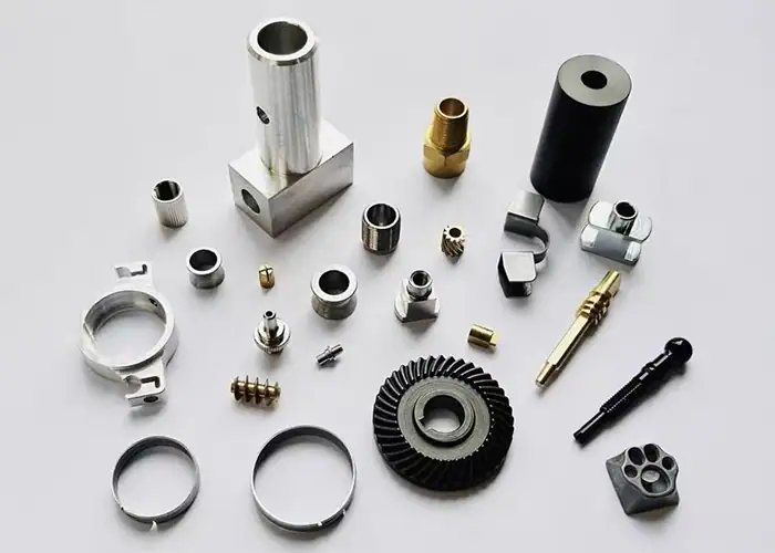
3+2 machining is well suited to components with features on multiple sides. Typical examples include valve bodies, manifolds, electronic housings, machine brackets, gearbox covers, fixture plates, and automation components.
Angled drilling is another strong application. The machine can index the workpiece so the hole axis aligns with the spindle, allowing stable drilling, reaming, counterboring, or tapping with conventional tools.
Deep pockets may also benefit from 3+2 positioning. Tilting the workpiece or spindle can improve tool access and allow a shorter cutter, reducing chatter and deflection compared with a long tool used vertically.
The method is also suitable for mold inserts with several fixed draft angles, medical instruments with machined features on different faces, and prototypes that need complex access but not continuously changing contours.
For these parts, simultaneous movement may add programming time without improving function. Fixed indexed positions usually provide the required accuracy and finish at a more practical cost.
Parts Best Suited For Simultaneous 5-Axis Machining
Simultaneous machining is most valuable for freeform and highly contoured components. Impellers, turbine blades, blisks, propellers, and aerodynamic surfaces require the cutter to follow continuously changing geometry while avoiding neighboring features.
Medical applications include orthopedic implants, bone plates, surgical tools, and anatomical components. Their curved surfaces and complex transitions often benefit from smooth tool-axis changes and controlled cutter contact.
Mold and die components may require simultaneous finishing in deep cavities, around steep walls, or across surfaces that would otherwise need multiple indexed passes. Continuous motion can reduce blending work and improve visual consistency.
Complex tubes, ports, and undercuts may also require changing tool orientation during the cut. In these cases, simultaneous five-axis machining provides access that fixed-angle operations cannot achieve efficiently.
The value is highest when continuous motion improves part quality, eliminates another process, or makes the geometry manufacturable. It should not be selected only because the machine is available.
Aerospace, Medical, Automotive, And Mold Applications
Aerospace parts often combine thin walls, pockets, compound angles, and strict feature relationships. Structural brackets and housings may use 3+2 machining, while blades, impellers, and aerodynamic surfaces usually need simultaneous toolpaths.
Medical components have similarly varied requirements. Instrument bodies and device housings may be machined through indexed positions, while implants and curved surgical components can require continuous five-axis finishing.
Automotive applications include prototype suspension parts, engine components, transmission housings, intake parts, molds, and motorsport components. Multi-face housings are often suitable for 3+2, while port surfaces and complex prototypes may need simultaneous motion.
Moldmaking frequently uses both processes. Roughing, drilling, and planar features can be completed with 3+2 strategies. Simultaneous five-axis finishing is then applied to steep walls, deep ribs, sculpted cavities, and surfaces where tool angle affects finish.
The industry does not decide the process by itself. Two parts used in the same aircraft, medical device, or vehicle may require completely different machining strategies.
How To Choose Between 3+2 And 5 Axis Machining ?
The best choice begins with the part model and functional requirements. The supplier should identify which surfaces are critical, how tools can approach them, and whether the tool direction must change during cutting.
Tolerance, finish, quantity, inspection, lead time, and budget should then be considered together. The goal is to use the simplest process that can produce the part reliably.
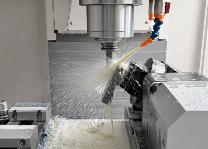
Choose 3+2 For Multi-Face And Angled Features
Choose 3+2 machining when the part has several faces, holes, pockets, or slots that can each be machined from a fixed orientation. This includes five-sided prismatic components and parts with multiple angled work planes.
It is also appropriate when the main objective is reducing manual setups. Keeping the part in one fixture improves datum consistency and avoids the time required to relocate it for each operation.
Stable indexed cutting is useful for roughing, drilling, tapping, reaming, and flat-surface finishing. It can provide high accuracy without the complexity of continuous rotary interpolation.
3+2 should also be considered when the quantity is low and programming cost matters. If simultaneous motion does not improve access or surface quality, there is little reason to add it.
Choose 5 Axis For Continuous Curves And Undercuts
Choose simultaneous 5-axis when the tool must remain at changing angles while moving across the surface. Typical indicators include freeform contours, twisted blades, changing draft angles, compound curvature, and complex undercuts.
It is also valuable when tool-holder clearance is a major problem. Continuously tilting the tool can prevent interference while maintaining a shorter and more rigid cutter.
Surface finish may justify full five-axis machining when several indexed tool directions would leave visible transitions. Continuous motion can produce a smoother result across connected contours and reduce manual polishing.
However, the drawing should identify the actual finish and profile requirements. Using full five-axis merely to create a visually complex toolpath does not improve a feature that could be machined more simply.
Compare Tolerance, Finish, Lead Time, And Budget
Start with geometry. Determine whether the features are planar, angled, curved, or undercut, and whether they can be grouped into a reasonable number of fixed tool orientations.
Next, review tolerance and datum relationships. A single multi-axis setup may improve positional consistency, but critical dimensions still depend on machine condition, rotary-axis calibration, workholding, thermal stability, tools, and inspection.
Surface requirements should be separated by function. A sealing face, bearing bore, and cosmetic contour do not need the same process. Simultaneous finishing may be justified for one surface while the rest of the part uses 3+2 machining.
Lead time should include programming, fixtures, material, machining, inspection, and any manual finishing. A faster cutting strategy is not necessarily faster overall if it requires extensive preparation or verification.
Finally, compare total cost rather than machine rate. The most economical solution may use 3+2 for most features and simultaneous five-axis only for the areas that cannot be produced effectively another way.
Common Process Selection Mistakes
Incorrect process selection can increase cost without improving part quality. It can also create unnecessary programming risk or lead to a design that remains difficult to fixture and inspect.
The most common mistakes come from treating five-axis machining as one fixed process and failing to analyze the part feature by feature.
Assuming Full 5-Axis Is Always Better
Simultaneous 5-axis machining offers greater motion freedom, but more movement is not automatically better. A fixed orientation can provide greater stability for many drilling, roughing, pocketing, and planar finishing operations.
Using continuous motion where it is not needed increases programming and simulation work. It may also introduce unnecessary rotary-axis movement, changing feed conditions, and additional opportunities for surface marks.
The better strategy is to match the toolpath to each feature. Many advanced components are produced with a combination of indexed and simultaneous operations rather than one method alone.
Buyers should also clarify what a supplier means by “5-axis.” A machine may have five controllable axes but be used mainly for indexed 3+2 machining. Parts that require continuous contouring should be identified specifically as simultaneous 5-axis work.
Ignoring Tool Access, Datums, And Workholding
A five-axis machine cannot solve every accessibility problem automatically. The fixture, clamps, table, spindle, and tool holder still occupy physical space and may block the required angle.
Designers should provide enough clearance around deep walls, undercuts, and closely spaced features. Internal corner radii should match practical cutter sizes, and deep cavities should not force unnecessary long-tool machining.
Datum selection also matters. The machining plan should keep critical features tied to stable references. Reducing setups is valuable only when the fixture locates the part securely and the datum strategy supports inspection.
Workholding should be considered before quoting. A small contact area, thin wall, or irregular casting may require custom fixtures, support structures, or additional operations regardless of the machine’s axis capability.
FAQs
Is 5 Axis CNC Machining Faster?
It can be faster for complex parts because it reduces setups and reaches multiple surfaces in one operation. For simple parts, 3-axis or 3+2 machining may be more efficient.
What Are The Limitations Of 5 Axis CNC?
Five-axis machining requires more expensive equipment, skilled programming, accurate simulation, and careful collision control. It may not be cost-effective for simple components.
Is 5 Axis CNC Hard To Learn?
It is more difficult than 3-axis machining because programmers must control tool orientation, rotary movement, and collision risks. Reliable CAM software and machine simulation are essential.
How Accurate Is A 5-Axis CNC Machine?
Accuracy depends on machine calibration, workholding, tooling, temperature control, and inspection. A well-controlled five-axis process can produce complex parts with tight tolerances.
Conclusion
The 3+2 vs 5 axis decision depends on how the tool must reach and follow the part. 3+2 machining is efficient for multi-face components, angled holes, pockets, and features cut from fixed orientations. Simultaneous 5-axis machining is better for freeform surfaces, changing tool angles, complex undercuts, and uninterrupted contour finishing. The most cost-effective process often combines both methods according to geometry, tolerance, finish, quantity, and inspection needs.
At TiRapid, we provide precision CNC machining and manufacturing services for complex prototypes and low-volume parts. Our team evaluates feature accessibility, tool orientation, workholding, tolerance, surface finish, and production requirements to determine whether 3+2 machining, simultaneous 5-axis machining, or a combined toolpath strategy offers the most practical result.