
Aluminum alloy turning involves specific machining challenges due to its low density, high thermal conductivity, and strong tendency to adhere to cutting tools. During machining, issues such as built-up edge formation, surface tearing, and dimensional variation can easily occur. Achieving stable machining results requires optimization across tooling, cutting parameters, chip evacuation, and clamping stability, improving both surface quality and machining efficiency.
Cutting Characteristics and Basic Control of Aluminum Alloy Machining
Aluminum alloys tend to form built-up edge and adhesive wear during turning. Although cutting forces are relatively low, tool sharpness and surface finish requirements are significantly higher. Machining stability mainly depends on heat distribution and friction behavior.
Thermal Conductivity and Deformation Control
Although aluminum dissipates heat quickly, localized temperature rise can still affect surface quality.
- Control heat concentration in the cutting zone to prevent local softening and tearing
- Maintain continuous cutting to reduce thermal fluctuations
- Use efficient cooling to reduce workpiece temperature rise
- Avoid dwelling in one area to prevent material adhesion
- Stabilize cutting force variations
- Maintain consistent machining rhythm to reduce heat accumulation
Stable thermal control improves surface uniformity.
Built-Up Edge Suppression Methods
Built-up edge directly affects dimensional accuracy and surface finish.
- Use sharp positive rake tools to reduce friction
- Increase cutting speed to reduce adhesion tendency
- Apply coated tools to improve chip evacuation
- Optimize feed rate to avoid cutting stagnation
- Keep cutting zone clean
- Maintain stable cutting temperature
Reducing built-up edge improves surface consistency.
Workpiece Rigidity and Clamping Stability
Aluminum has relatively low rigidity, making it prone to vibration and deformation during clamping.
- Use soft jaws to reduce clamping damage
- Control clamping force to avoid deformation
- Add support points to increase rigidity
- Reduce overhang length to minimize vibration
- Check fixture concentricity accuracy
- Maintain repeatable clamping conditions
Stable clamping improves machining reliability.
Aluminum Alloy Turning Tool Selection Techniques
Cutting tools are core components in aluminum turning. Their performance directly affects cutting stability, surface finish, and machining efficiency. Because aluminum is soft and prone to adhesion, tool sharpness, surface smoothness, and chip evacuation capability are critical. Incorrect tool selection may still cause built-up edge, adhesion, or dimensional drift even if parameters are correct.
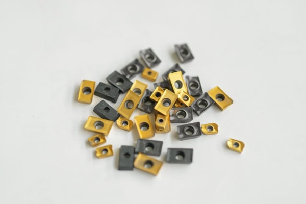
Tool Geometry Optimization
Tool geometry determines material flow and friction during cutting.
- Use large positive rake angle to reduce cutting resistance and deformation
- Increase clearance angle to reduce contact friction and heat
- Improve cutting edge sharpness to reduce tearing and built-up edge
- Optimize nose radius for balance between rigidity and surface finish
- Use polished rake face to improve chip flow
- Adjust geometry for roughing and finishing stages
- Control edge hone condition to prevent adhesion
Optimized geometry improves chip flow and produces finer surface texture.
Tool Material and Coating Selection
Different aluminum grades require different tool systems.
- Ultra-fine grain carbide for high precision machining
- Mirror-polished tools for anti-adhesion finishing
- DLC coatings reduce friction coefficient
- Uncoated sharp tools for ultra-fine surface finishing
- Tough tools for interrupted cutting conditions
- Select tool grade based on silicon content and hardness
- Prefer heat-resistant tools for high-speed machining
Proper material selection extends tool life and stability.
Tool Wear Control Strategy
Tool wear directly affects dimensional consistency.
- Inspect tool tip wear and chipping regularly
- Monitor changes in cutting sound and vibration
- Track dimensional deviation trends
- Avoid machining with severely worn tools
- Control cutting load to reduce abnormal wear
- Establish replacement cycle for batch production
- Perform test cuts to verify tool condition
Stable wear control improves consistency.
Tool Selection and Process Matching Strategy
Tool selection must consider machining conditions.
- Use tough tools for roughing to withstand impact
- Use sharp tools for finishing to improve surface quality
- Use low-friction coatings for high-speed machining
- Use wear-resistant tools for long production runs
- Use anti-chipping tools for interrupted cutting
- Choose stable tools for high-precision small batches
Proper matching improves overall machining stability.
Cutting Parameter and Cooling Optimization Methods
Cutting parameters strongly influence machining stability. The relationship between speed, feed, and depth of cut determines heat generation, cutting force, and surface quality trends.
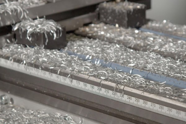
Cutting Speed Optimization
Cutting speed affects both productivity and material deformation behavior.
- Adjust speed range according to material grade
- Maintain stable spindle speed to avoid fluctuation
- Separate roughing and finishing speed strategies
- Avoid low-speed cutting that causes adhesion
- Match cutting speed with tool sharpness
- Determine optimal stable range via trial cutting
- Control speed fluctuation for consistency
Stable speed reduces thermal accumulation.
Coolant Usage Strategy
Cooling systems affect both temperature and chip evacuation.
- Use high-flow coolant to flush cutting zone
- Optimize nozzle direction toward tool tip
- Select low-viscosity coolant for better flow
- Adjust cooling intensity during finishing
- Filter coolant to avoid contamination
- Maintain stable pressure system
- Prevent dead zones in coolant flow
Good cooling significantly improves tool life and surface finish.
Feed and Depth of Cut Control
These parameters determine cutting load and stability.
- Use larger depth of cut for roughing efficiency
- Reduce feed rate during finishing for surface quality
- Avoid sudden load changes causing vibration
- Maintain uniform cutting thickness
- Use layered machining strategies
- Adjust feed according to tool rigidity
- Keep cutting continuous and stable
Proper combination reduces dimensional variation.
Chip Evacuation and Surface Quality Improvement
Aluminum often forms continuous chips during turning. If chips are not broken and evacuated properly, they may wrap around the tool or workpiece, causing scratches, dimensional deviation, and tool damage.
Chip Formation Mechanism and Control
Chip shape depends on material deformation and shear stability.
- Adjust shear angle to control chip curl radius
- Use cutting speed to influence plastic flow
- Adjust feed rate to change chip thickness
- Optimize rake angle to reduce adhesion
- Control temperature to change material softening
- Use chip breaker geometry to induce fracture
Stable chip formation improves machining continuity.
Chip Breaker and Structural Optimization
Tool geometry plays a key role in chip control.
- Use dedicated aluminum chip breaker inserts
- Polish rake face to reduce friction
- Adjust tool angle to guide chip flow
- Optimize nose radius to avoid entanglement
- Use positive rake geometry for smooth flow
- Maintain clear chip evacuation path
Proper structure prevents chip accumulation.
Coolant and Chip Evacuation Synergy
Cooling directly affects chip breakage efficiency.
- Use high-pressure coolant at cutting zone
- Position nozzle toward chip exit path
- Combine intermittent and continuous cooling
- Increase coolant flow for chip flushing
- Avoid dead zones causing chip buildup
- Maintain filter system regularly
Synergy reduces tool load significantly.
Surface Roughness Formation and Improvement
Surface quality is affected by chip evacuation and tool condition.
- Use sharp tools for finishing
- Increase cutting speed to reduce adhesion
- Control feed rate for lower roughness
- Optimize nose radius transition
- Avoid secondary cutting marks
- Maintain continuous cutting process
Improved surface quality enhances assembly precision.
Chip Entanglement and Machine Safety Control
Chip entanglement affects both quality and safety.
- Install automatic chip conveyors
- Use chip removal systems
- Regularly clean chip channels
- Reduce long chip formation ratio
- Prevent chip wrapping on spindle or fixture
- Monitor machine operation continuously
Safety control improves production stability.
Process Synergy for Surface Stability
Surface stability depends on multiple interacting factors.
- Maintain stable tool wear condition
- Optimize cutting parameters consistently
- Reduce machine vibration influence
- Ensure stable cooling system operation
- Standardize machining parameter system
- Perform trial cuts for optimization
Multi-factor synergy ensures stable surface quality.
















