In plastic CNC machining, tool condition directly affects part surface quality, dimensional accuracy, and overall processing efficiency. Unlike metal machining, plastics are characterized by low hardness and poor thermal conductivity. As a result, the window between the onset of tool wear and noticeable degradation in machining results is often quite narrow. Catching tool wear at an early stage and replacing the tool in time not only helps avoid producing batches of defective parts, but also reduces the risk of surface damage caused by excessively worn tooling. For these reasons, understanding the early warning signs of tool wear in plastic CNC machining is essential for maintaining both quality control and cost efficiency.
Subtle Changes in Surface Quality
Gradual Increase in Surface Roughness
In the initial stages of tool wear, the most direct signal comes from the part surface itself. As the cutting edge begins to dull, cutting resistance increases, and the plastic surface may develop slightly deeper tool marks or a rise in roughness. These changes can be subtle at first, but they are usually detectable when comparing parts from the same batch side by side. If a run of consecutively machined parts shows a progressive decline in surface quality, the tool condition should be checked.
Hazing or Whitening on Transparent Materials
For transparent or translucent plastics such as acrylic and polycarbonate, early signs of tool wear are more visually apparent. When the cutting edge is no longer sharp enough, increased friction and pressure are applied to the material surface during cutting. Heat buildup leads to localized temperature rise, causing hazy patches or slight whitening to appear on transparent parts. These effects are absent at the start of machining and become progressively more pronounced as tool wear advances.
- Surface hazing is often one of the earliest indicators of tool wear
- If the haze remains after polishing, the surface damage has already penetrated beneath the outermost layer of the material
- Transparent parts demand a higher level of tool sharpness than standard engineering plastics
Changes in blade shape
The blade shape changed from uniform to irregular
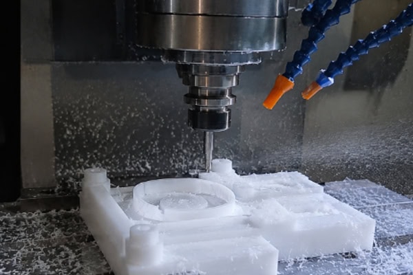
When a tool is sharp, plastic chips typically appear as consistent flakes or granules. As the tool begins to wear, chip morphology changes noticeably: chips become uneven in size, irregular in shape, and may even show signs of fracturing or crumbling. This shift occurs because a worn cutting edge can no longer sever the material cleanly. Instead, a combination of partial cutting and partial compression takes place, causing the chip form to lose its consistency.
Increased Proportion of Powdery Chips
When machining materials such as POM or acrylic, normal cutting should produce uniform small flakes or granules. If the proportion of fine powder in the chips increases noticeably, it indicates that the tool is rubbing against the material rather than cutting it. More powder means more friction, and higher temperatures in the cutting zone. Left unaddressed, this will affect both surface finish and dimensional accuracy.
- Consistent, uniform chips indicate stable cutting conditions and good tool condition
- Irregular, oversized chip fragments may signal that micro-chipping has already occurred on the cutting edge
- An increase in long, stringy chips suggests that frictional heat is causing the material to soften
Increased Burr Formation on Part Edges
Burrs Grow in Size and Number
As the tool wears, its ability to cleanly sever the material diminishes. Along part edges, particularly at exit points, burrs become larger and more numerous than under normal conditions. If parts machined with the same program and parameters begin showing noticeably worse burr conditions than before, this is usually a direct reflection of tool condition.
Slight Edge Whitening or Chipping
For relatively brittle materials such as polycarbonate and acrylic, tool wear can also cause localized whitening along edges (stress whitening), or even tiny chips at exit points. These phenomena do not occur when the tool is sharp. Once they start to appear, tool condition should be the first item to investigate.
Changes in Machining Sound and Machine Load
Cutting Sound Shifts from Crisp to Dull
When the cutting edge is sharp, the machining sound is typically clean and continuous. As the edge wears, the sound becomes lower and duller, sometimes accompanied by irregular noise. This happens because a worn tool produces unstable cutting resistance, with increased friction and squeezing of the material, which alters the vibration pattern. Experienced operators can often detect changes in tool condition through these audible shifts before other signs appear.
Spindle Load Gradually Increases
Although cutting forces for plastics are far lower than those for metals, tool wear still registers on spindle load readings. If the spindle current or load value shows a consistent upward trend while machining identical parts with unchanged parameters, the tool should be inspected for wear. This change is typically gradual, making it a useful early-warning indicator.
Slight Dimensional Drift in Parts
Tool wear can also lead to gradual dimensional drift. A worn tool generates higher cutting forces, and the degree of workpiece deflection during cutting differs from that produced by a sharp tool. Holes may come out slightly undersized or oversized, and external dimensions may show subtle deviations. These shifts often hover near the tolerance limits, making them easy to overlook, but the trend usually becomes apparent when multiple parts are measured in sequence.
Frequently Asked Questions
Does tool wear occur faster when machining plastics than when machining metals?
Not necessarily. Plastics are far softer than metals, and under normal conditions, tool wear rates when cutting plastics are not higher than those for metal cutting. That said, tool wear in plastic machining has its own characteristics. First, the poor thermal conductivity of plastics means that cutting heat tends to concentrate around the tool edge, and elevated temperatures can accelerate wear. Second, certain filled or reinforced plastics—such as glass-fiber-reinforced grades—exert a stronger abrasive effect on cutting tools. Third, improper machining parameters that lead to material sticking or melting can indirectly shorten tool life. With appropriate tool selection and machining parameters, tool life in plastic machining can generally be maintained within the expected range.
At what point should a worn tool be replaced?
A tool should be replaced when part surface quality can no longer meet requirements, when burrs have become significantly larger and cannot be remedied through deburring, or when dimensions begin drifting beyond tolerance. For precision plastic part production, it is advisable to adopt a statistical process control approach: track tool service life and the number of parts machined, then determine a reasonable replacement interval based on part inspection data, rather than waiting until clearly defective parts appear.
In conclusion
Tool wear in plastic CNC machining is a gradual accumulation process. Early indicators tend to manifest across multiple dimensions—surface quality, chip morphology, edge burrs, machining sound, and dimensional changes. Paying attention to these subtle shifts and establishing a routine for tool inspection and tool-life management makes it possible to replace tools before they enter the rapid-wear phase, avoiding batch-level quality problems. For transparent parts and precision components with stringent appearance requirements, tool condition monitoring is especially critical, as it has a direct bearing on both machining efficiency and final product quality.