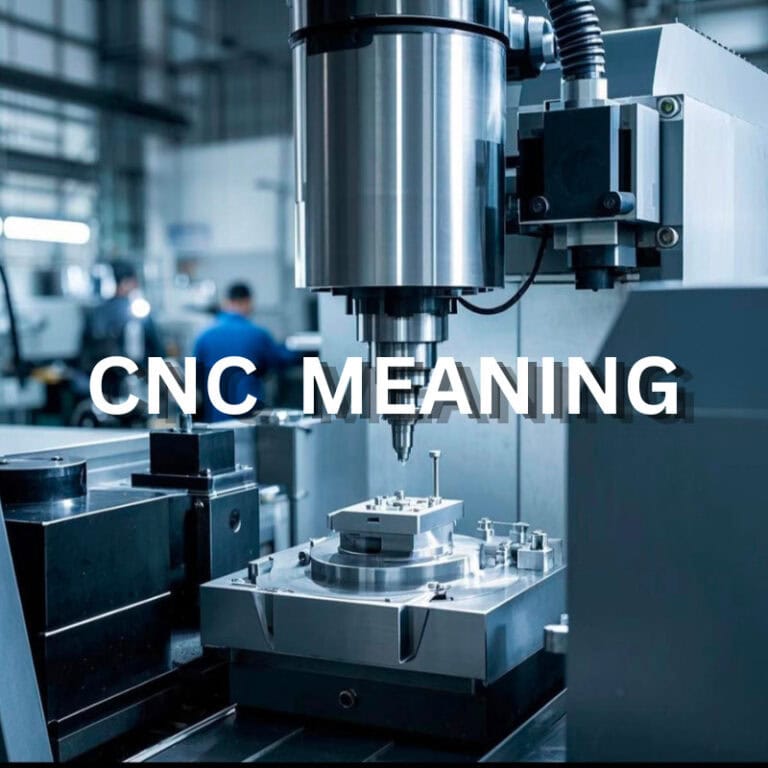
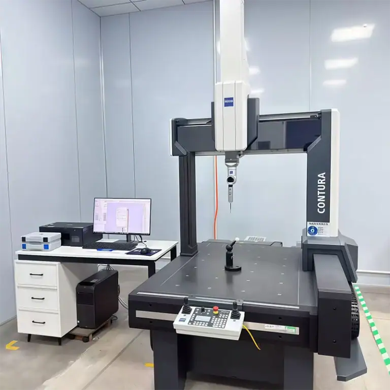
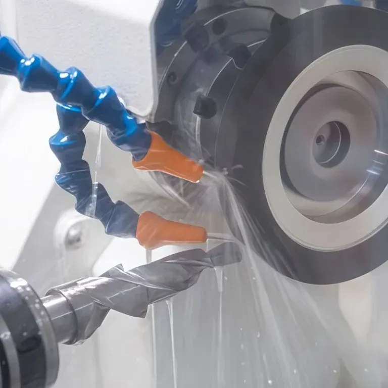
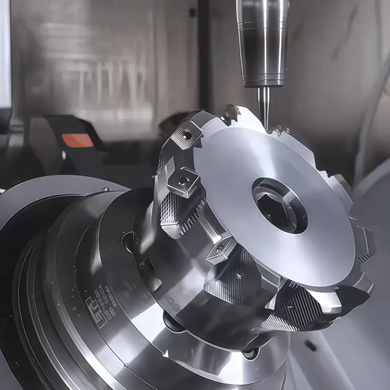
Automated inspection equipment uses sensor brackets, camera mounts, precision locating blocks, and inspection fixtures that must meet requirements for installation, component positioning, and repeatable inspection. Dimensional or structural deviations can affect inspection consistency and increase equipment assembly and commissioning work. A suitable machining plan should account for component geometry, material properties, operating conditions, and acceptance criteria. Appropriate process planning and targeted inspection help ensure that finished components meet their intended requirements.
Machining Challenges for Automated Inspection Equipment Components
Manufacturing requirements depend on how each component is installed and the function it performs. Different structures require corresponding machining strategies.
Positioning Structures and Installation Accuracy
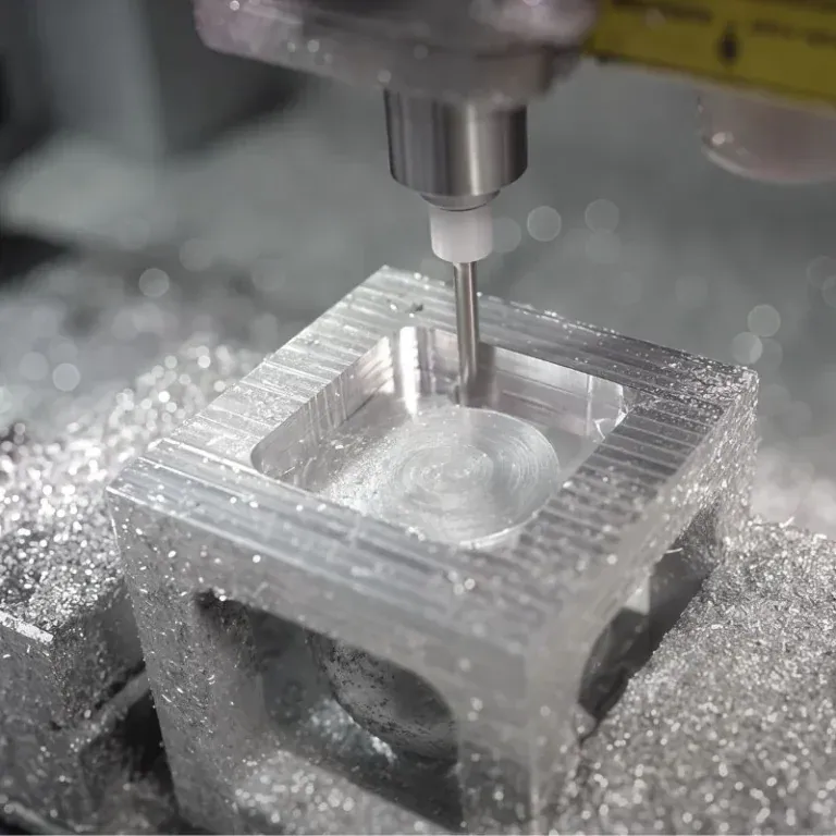
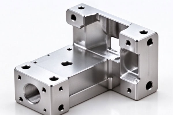
Positioning components are commonly connected to other parts through holes, datum surfaces, or mating features. Hole spacing, diameters, and positional deviations must be controlled according to the drawings. Components with complex contours require carefully planned workholding to reduce errors caused by repeated positioning. Thin-walled parts may deform during clamping and cutting, so clamping force and machining sequence should be adjusted to maintain their shape and dimensions.
Material Properties and Environmental Suitability
Material selection affects cutting methods, dimensional stability, and component performance. The manufacturing plan should reflect the intended operating environment.
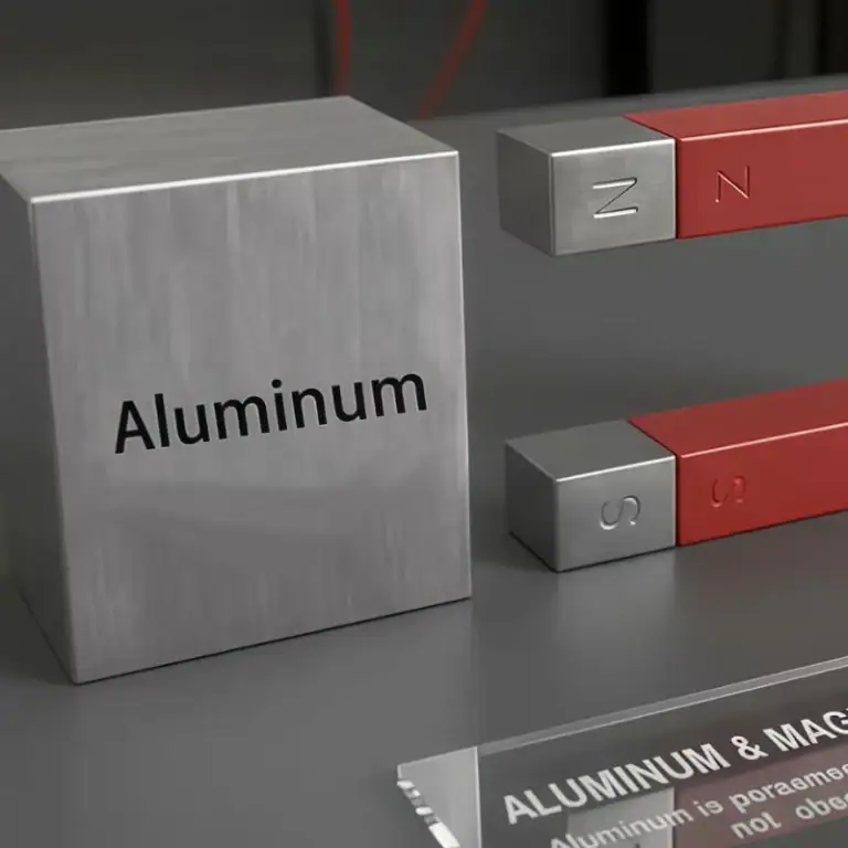
- Aluminum Alloys: Suitable for some lightweight brackets and mounts, aluminum alloys require attention to deformation in thin-walled areas and the resulting surface quality.
- Steel and Stainless Steel: These materials can be selected according to requirements for rigidity, wear resistance, or corrosion resistance. Machining parameters and subsequent treatments must be compatible with the specific material.
- Engineering Plastics: Materials such as POM and nylon are used for some insulating structures and positioning fixtures. However, their thermal expansion is generally higher than that of common metals, and nylon may also absorb moisture. Operating conditions and inspection environments should therefore be considered.
Dimensional stability under changing temperature and humidity conditions is an important consideration for plastic components.
CNC Machining Processes and Surface Treatment Planning
Once material and structural requirements are established, machining sequence, deformation control, and surface treatment should be planned together to prevent subsequent processes from affecting critical dimensions.
Controlling Machining Deformation and Dimensional Variation
Clamping, material condition, and temperature changes can cause dimensional deviations during machining. The following measures can help manage these risks:
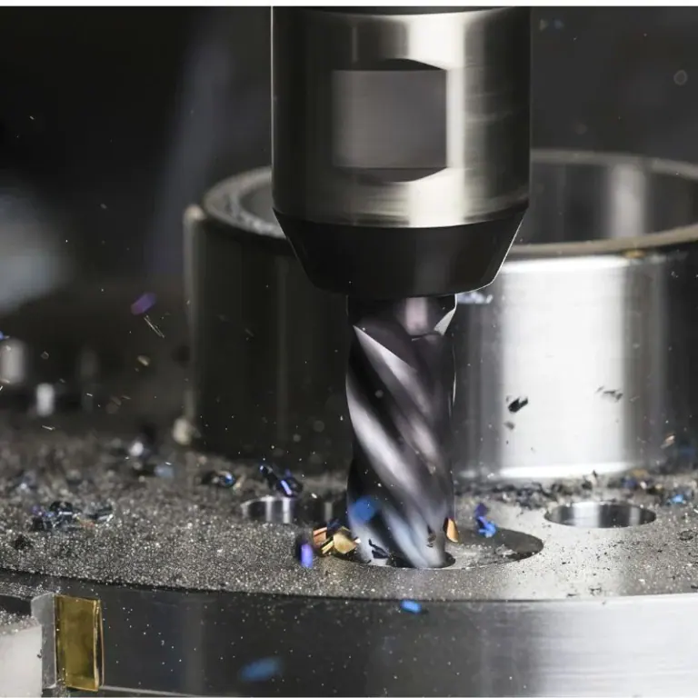
- Staged Machining: For components with complex structures or substantial machining allowances, rough machining can be followed by finishing as appropriate, leaving sufficient allowance for critical dimensions.
- Assessing Residual Stress: For metal components with a higher risk of deformation, the need for stress-relief treatment should be evaluated based on material condition, component dimensions, and tolerance requirements. It should not be treated as a mandatory process for every part.
- Consistent Inspection Conditions: Components with tight dimensional requirements should be measured under suitable temperature conditions. Where necessary, critical dimensions can be rechecked after machining to confirm compliance with the drawings.
Maintaining appropriate and consistent inspection conditions helps reduce the influence of the measurement environment on inspection results.
Selecting Surface Treatments According to Material
Surface treatment should serve the component’s intended purpose while accounting for changes in dimensions, appearance, and mating relationships. Aluminum alloys may be evaluated for anodizing according to their grade and functional requirements, with particular attention to the effects of the coating on hole diameters, mating surfaces, and overall dimensions. Steel components may use black oxide, passivation, or other suitable treatments depending on the material and operating environment. For engineering plastics, the material should first be confirmed as suitable for the application. If coloring or another surface treatment is required, its effects on dimensions, surface condition, and subsequent assembly should be evaluated.
Quality Inspection of Automated Inspection Equipment Components
Inspection criteria should reflect the component’s actual function. In addition to dimensional verification, inspection should cover the features that affect assembly and positioning accuracy.
Defining Critical Dimensions and Inspection Items
Acceptance requirements vary by component type. Inspection plans should be developed according to the engineering drawings and assembly requirements.
| Component Type | Key Inspection Items | Inspection Purpose |
| Sensor Brackets | Mounting hole positions, datum surfaces, and perpendicularity | Confirm correct installation positioning |
| Camera Mounts | Hole spacing, flatness, and mating dimensions | Ensure proper camera installation and positioning |
| Precision Locating Blocks | Locating holes, contours, and critical dimensions | Meet workpiece positioning requirements |
| Engineering Plastic Fixtures | Critical dimensions, deformation, and material condition | Reduce dimensional deviations caused by environmental changes |
| Surface-Treated Components | Final dimensions and coating or treatment requirements | Confirm compliance with requirements after treatment |
Defining inspection items according to component function makes acceptance checks more relevant to actual assembly and operating needs.
Maintaining Batch Consistency and Long-Term Stability
Passing the initial sample inspection does not automatically guarantee that subsequent production batches will meet the same requirements. Batch production therefore requires an appropriate quality control process.
- Batch Inspection: Determine whether sampling or full inspection is appropriate based on order quantity, component risk, and customer requirements. Retain necessary dimensional records.
- Verification of Critical Features: Establish clear acceptance criteria for dimensions that affect installation and positioning. If deviations occur, review the machining and workholding processes.
- Change Management: When materials, machining processes, or surface treatments change, reassess the relevant dimensions and assembly requirements instead of automatically applying the original inspection results.
Reviewing manufacturing changes helps maintain quality consistency between production batches.
How to Choose a Machining Supplier for Automated Inspection Equipment Components
Choosing a machining supplier affects not only whether components are delivered according to the drawings but also subsequent assembly, acceptance, and production planning.
Evaluating Machining Capabilities and Process Control
Supplier capabilities should be assessed against the component drawings and actual manufacturing requirements.
- Dimensional Control: Confirm that the supplier can interpret critical dimensions, tolerances, and datum requirements and has suitable measuring equipment.
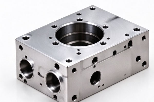
- Complex Component Machining: For parts with multiple holes, thin walls, or features machined from several sides, review whether the supplier’s workholding and process sequence suit the component geometry.
- Coordination of Post-Processing: If surface treatment is required, clarify the process scope, dimensional effects, and final acceptance responsibilities in advance.
Early coordination between machining and post-processing helps reduce dimensional disputes at delivery.
Providing Complete Drawings and Acceptance Requirements
Clear technical documentation helps prevent misunderstandings during quotation, machining, and delivery.
- Engineering Files: Provide the latest 2D drawings, 3D models, material grades, tolerances, and surface treatment specifications.
- Operating Conditions: Explain the component’s installation position, mating relationships, and operating environment so that material and process suitability can be assessed.
- Order Information: Confirm order quantities, delivery schedules, inspection criteria, and packaging requirements in advance to help the supplier organize production and delivery.
Clear order and acceptance requirements help reduce communication gaps during production planning and delivery.
The machining quality of automated inspection equipment components depends on structural assessment, process planning, and dimensional inspection. Before placing an order, businesses should define critical tolerances, material requirements, and acceptance criteria, evaluate suppliers according to the specific component requirements. TiRapid provides precision CNC machining services tailored to customer drawings, materials, and order needs, supporting the manufacture of automated inspection equipment components.