
A sink mark is a visible depression or shallow dimple that forms on the surface of an injection molded plastic part. It usually appears above thick sections, ribs, bosses, internal supports, or areas where the plastic cools unevenly. Although a sink mark may look like a cosmetic defect, it often reflects deeper design, tooling, material, or process balance problems.
This guide explains what a sink mark is, how sink marks form during injection molding, why wall thickness and packing pressure matter, how material behavior affects shrinkage, how to inspect sink defects, and what design and process changes can help reduce sink marks in molded plastic parts.
What Is a Sink Mark in Injection Molding?
A sink mark is one of the most common injection molding defects, especially on plastic parts with thick geometry or uneven wall sections. It appears when the outer surface of the molded part cools and hardens before the internal material has fully cooled and stabilized.
How a Sink Mark Appears on Plastic Parts?
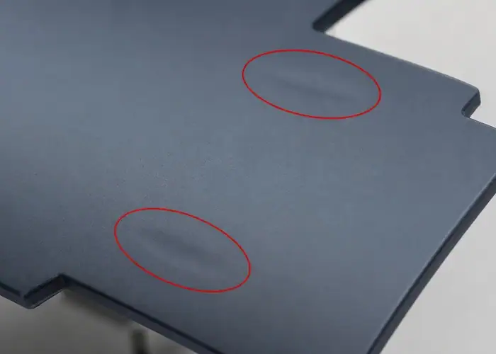
A sink mark usually appears as a small depression, dimple, shallow groove, or uneven surface area on the molded part. It may be easy to see on glossy, flat, dark, or highly cosmetic surfaces because reflected light makes the depression more noticeable. On textured surfaces, the defect may be less visible but still present.
The defect often forms opposite thick internal features. For example, a visible sink may appear on the front cosmetic surface above a boss, rib, mounting post, or thick transition on the back side of the part. This is why sink marks are not only a surface problem, they are closely connected to the internal geometry of the molded component.
In some parts, the sink mark is mainly cosmetic. In other cases, it can affect sealing, assembly fit, product feel, dimensional stability, or customer acceptance. The impact depends on where the defect appears, how deep it is, whether the surface is visible, and whether the area has a functional requirement.
Why Sink Marks Are More Than Cosmetic Defects?
Many sink marks are rejected because they reduce the visual quality of molded products. A consumer-facing cover, housing, handle, or display frame may fail inspection even if the part remains strong enough. For visible parts, small depressions can suggest poor molding quality or weak design control.
However, sink marks can also indicate internal shrinkage or poor packing. If the same area continues to sink during production, the part may have uncontrolled cooling, low cavity pressure, or excessive wall thickness. These conditions can also affect dimensions, flatness, and repeatability between production batches.
For engineering plastic parts, the question is not only whether the sink mark can be seen. Engineers should ask why it formed, whether the root cause affects performance, and whether the defect will become worse with process variation. A stable molding process should control both appearance and geometry.
Where Sink Marks Commonly Occur?
Sink marks are common near ribs, bosses, screw posts, gussets, thick corners, molded logos, snap-fit bases, and areas where several walls join together. These regions contain more plastic volume than surrounding areas, so they cool more slowly and shrink differently from thinner sections.
They can also occur near gates or flow-end areas when packing pressure is not transferred effectively. If the gate freezes too early, the cavity can no longer receive extra material to compensate for shrinkage. The result may be a sunken surface in thicker zones that still need material support during cooling.
Parts with inconsistent wall thickness are more likely to show sink marks. A sudden change from thin wall to thick wall creates uneven cooling and stress. Good plastic part design aims to keep wall thickness balanced and to support features with geometry that reduces localized material buildup.
How Sink Marks Form During the Molding Process?
Sink marks form because injection molded plastic shrinks as it cools. The outside surface cools first because it touches the colder mold steel. The inner core of thick sections cools more slowly, and as it contracts, it pulls the already hardened outer skin inward.
Uneven Cooling Between Surface and Core
During injection molding, hot molten plastic fills the mold cavity and begins to cool immediately against the mold wall. The surface layer freezes first and forms the visible skin of the part. In thin sections, the whole wall cools relatively evenly, so shrinkage is easier to control.
In thick sections, the core stays hot longer after the outer skin has already solidified. As the core cools, it continues to shrink. If the core cannot be packed with enough additional material before the gate freezes, it pulls inward and creates a visible depression on the part surface.
This is why sink marks are often linked to thick walls, ribs, bosses, and heavy internal features. The thicker the section, the greater the difference between surface cooling and core cooling. Without design correction or process compensation, the molded part may sink in the same location again and again.
Role of Packing Pressure and Hold Time
After the mold cavity is filled, packing and holding pressure help push additional material into the cavity to compensate for cooling shrinkage. This stage is critical for sink mark control because the part is no longer simply being filled, it is being stabilized while the plastic cools.
If packing pressure is too low, the thick section may not receive enough material. If hold time is too short, the cavity may stop receiving pressure before the part has stabilized. In both cases, the internal plastic shrinks without enough compensation, and the surface may pull inward.
The gate must also stay open long enough for packing pressure to work. If the gate freezes too early, increasing hold time may not help because no additional material can enter the cavity. This makes gate size, gate location, packing pressure, and cooling time closely connected in sink mark prevention.
Why Thick Features Create Higher Sink Risk?
Thick features contain more molten plastic volume, and more volume means more shrinkage potential. A boss or rib that is too thick at its base can create a local mass of material behind a visible surface. As that mass cools, it pulls on the surface and creates a sink mark.
The problem becomes more serious when the thick feature is connected directly t o a cosmetic wall. A screw boss behind a flat housing surface is a common example. If the boss base is too large or too thick, the outer surface may show a round depression even if the mold surface is perfectly polished.
Good design reduces localized material buildup. Instead of using a solid thick boss or heavy rib, engineers can use coring, thinner rib sections, gusset optimization, or balanced wall transitions. The goal is not to remove strength, but to create strength with less uneven plastic mass.
Main Causes of Sink Marks
Sink marks rarely come from one factor alone. They are usually caused by a combination of part geometry, mold design, material shrinkage, and injection molding process settings. Understanding the cause helps avoid random process adjustments that do not solve the real problem.
Poor Wall Thickness Design
Uneven wall thickness is one of the most common design causes of sink marks. When one area of the part is much thicker than the surrounding wall, it cools more slowly and shrinks more. The surface above that thick area may then collapse inward and create a visible defect.
Plastic part walls should be as uniform as practical. When thickness changes are necessary, transitions should be gradual rather than sudden. A sharp change from a thin wall to a thick boss or heavy rib increases sink risk because the thicker section acts as a thermal mass during cooling.
Designers should review wall sections early in the project. A small CAD adjustment before tooling may prevent repeated molding trials later. Reducing unnecessary thickness, hollowing heavy areas, and redesigning support features can improve both appearance and cycle stability.
Oversized Ribs, Bosses, and Internal Supports
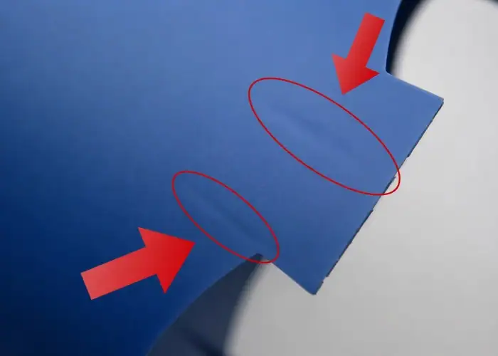
Ribs and bosses are useful because they add strength, alignment, and assembly features without making the whole part thick. However, if these features are too thick, they become a direct source of sink marks. The base of a rib or boss is especially important because it sits behind the visible surface.
A common design rule is to keep rib thickness lower than the nominal wall thickness. The exact ratio depends on material, part function, surface requirement, and tool design. If the rib is too thick, the extra plastic volume at the base may shrink and pull the opposite surface inward.
Bosses should also be designed with core holes, proper wall sections, and support ribs instead of solid mass. A large solid boss may feel strong in CAD, but it can create sink, long cooling time, and internal stress. A cored boss with balanced support often molds better and performs more consistently.
Insufficient Packing Pressure
Packing pressure helps compensate for material shrinkage during cooling. If the pressure is not high enough, thick regions may not be packed fully. This can leave the internal volume under-supported, which increases the chance of a surface depression after the part cools.
Low packing pressure may come from conservative process settings, flow restrictions, early gate freeze, or pressure loss through long flow paths. The machine setting alone does not guarantee proper cavity pressure. What matters is whether pressure reaches the area that needs compensation.
Increasing packing pressure can reduce sink marks in some cases, but it is not a universal fix. Too much pressure can create flash, stress, difficult ejection, or dimensional problems. The correct approach is to balance pressure, gate design, material behavior, and part geometry.
Short Hold Time or Early Gate Freeze
Hold time controls how long packing pressure is applied after filling. If hold time ends too early, the part may continue to shrink after pressure is removed. Thick sections are especially sensitive because they need more time to cool and stabilize than thin sections.
Gate freeze is a key limit. Once the gate freezes, no more plastic can enter the cavity, even if hold pressure continues. If the gate is too small or cools too quickly, the thick sections may not receive enough material to compensate for shrinkage, and sink marks may appear.
A molding trial should confirm whether hold time is long enough and whether the gate remains open during effective packing. Part weight studies, cavity pressure data, and dimensional checks can help determine when additional hold time no longer improves packing.
Design Strategies to Prevent Sink Marks
Good sink mark prevention starts before the mold is built. Once the tool is finished, some corrections are still possible, but design-related sink marks are much easier to solve in CAD than during production. Part geometry should be reviewed with molding behavior in mind.
Maintain Uniform Wall Thickness
Uniform wall thickness helps the plastic cool at a more consistent rate. When the entire part has similar wall sections, shrinkage is easier to predict, packing is more stable, and the risk of localized sink marks is reduced. This is one of the most important principles in injection molded part design.
Uniform does not mean every area must be identical, but sudden thickness changes should be avoided. If a part needs a thicker region for strength or function, the transition should be gradual. Smooth changes help the plastic flow and cool more evenly without creating a concentrated shrinkage zone.
Design review should include section analysis through ribs, bosses, corners, and mounting areas. Areas that look acceptable from the outside may hide thick internal geometry. Checking wall thickness early helps prevent sink marks before the mold design is locked.
Optimize Rib and Boss Geometry
Ribs should provide stiffness without adding too much material. A rib that is too thick can create a sink mark on the opposite surface, while a rib that is too thin may not provide enough strength or may be difficult to fill. The best rib design balances strength, fill behavior, and cooling.
Bosses should usually be cored rather than solid. A cored boss reduces material mass while still allowing screws, inserts, or alignment functions. Support ribs can strengthen the boss, but their thickness and base geometry must also be controlled to avoid creating new sink risks.
Corners and intersections need special attention. When several ribs meet at one boss, the combined plastic volume may be much thicker than the nominal wall. Reducing intersection mass, adding radii carefully, and spreading support features can lower sink risk while keeping the assembly function.
Use Coring and Material Reduction
Coring removes unnecessary internal plastic from thick sections. Instead of molding a solid block, the design uses hollowed areas, recesses, or internal geometry to keep the wall section closer to the nominal thickness. This helps reduce cooling time and shrinkage concentration.
Material reduction should be done carefully. Removing too much material may weaken the part, create flow hesitation, or cause ejection problems. The goal is to reduce excess mass while maintaining load paths, screw strength, sealing surfaces, and assembly requirements.
Coring is especially useful for handles, thick housings, structural blocks, bosses, and cosmetic parts with heavy backside features. When designed well, it can improve appearance, reduce cycle time, lower part weight, and make the molding process more stable.
Process Control for Reducing Sink Marks
Even a well-designed part can develop sink marks if the molding process is not controlled correctly. Injection molding settings determine how the cavity fills, how pressure is applied, how long the plastic is packed, and how evenly the part cools before ejection.
Adjust Packing Pressure and Holding Time
Packing pressure and hold time are usually the first process areas to review when sink marks appear. If the part is under-packed, increasing packing pressure or extending hold time may help push more material into thick sections before the gate freezes.
The adjustment should be controlled and measured. A process engineer may track part weight, dimensions, appearance, and cavity pressure to understand whether the change is improving packing. If part weight stops increasing, the gate may already be frozen and extra hold time may not help.
Excessive packing can create other defects. Flash, stress marks, warpage, difficult ejection, or oversize dimensions may appear if pressure is too high. The best setting is not the highest pressure, it is the stable pressure that fills shrinkage needs without damaging the rest of the part quality.
Control Melt and Mold Temperature
Melt temperature affects viscosity, flow, packing behavior, and cooling time. If the melt is too hot, the part may take longer to cool and shrink more after the surface has hardened. If the melt is too cold, the cavity may not pack properly, and flow restrictions can increase local defects.
Mold temperature also matters. A mold that is too hot may extend cooling time and allow more shrinkage before ejection. A mold that is too cold may freeze the surface too quickly while the core remains hot, making surface sink more visible in some conditions.
Temperature control should be stable across the tool. Uneven cooling channels, hot spots, blocked water lines, or poor thermal balance can create sink marks in repeatable locations. Good mold temperature management supports consistent shrinkage and better cosmetic results.
Improve Cooling Time and Cooling Layout
Cooling time allows the part to solidify enough before ejection. If the part is ejected too early, thick sections may continue shrinking outside the mold, and the surface may sink further after release. Increasing cooling time can reduce visible sink, but it also increases cycle time.
Cooling layout is often more important than simply adding time. If cooling channels are too far from thick features, the part may cool unevenly. Local hot spots near bosses or heavy sections can produce sink marks even when the overall cycle seems long enough.
A good tool design places cooling where thermal load is highest. Conformal cooling, baffles, bubblers, high-conductivity inserts, or improved water flow may be considered for difficult parts. The goal is to remove heat evenly, not just slowly.
Material Behavior and Sink Mark Risk
Different plastics shrink at different rates and respond differently to packing, cooling, wall thickness, and tool temperature. Material choice can strongly affect sink mark risk, especially when the part includes thick areas or cosmetic surfaces.
Shrinkage Rate and Resin Type
Materials with higher shrinkage rates generally create higher sink risk when geometry is not balanced. Semi-crystalline materials often shrink more than amorphous materials because of their molecular structure and crystallization behavior during cooling. This can make thick sections more sensitive.
Amorphous plastics may show lower shrinkage in many cases, but they can still develop sink marks if ribs, bosses, or thick walls are poorly designed. No material can fully overcome a severe geometry problem. Resin behavior must be considered together with part design.
Material datasheets provide shrinkage ranges, but real shrinkage depends on processing conditions, wall thickness, flow direction, mold temperature, and packing. For critical parts, mold flow analysis and trial data are more useful than relying only on a general shrinkage number.
Filled and Reinforced Plastics
Glass-filled or mineral-filled plastics often shrink less than unfilled materials, which can help reduce some sink risk. However, filled materials also create different flow behavior, anisotropic shrinkage, and surface appearance challenges. They may improve stiffness but still require careful design.
Reinforced plastics can show different shrinkage along and across the flow direction. This may affect flatness, warpage, and dimensional stability. A sink mark may not be the only concern, the part may also distort if fiber orientation and wall thickness are not balanced.
Filled materials can also make cosmetic surfaces more sensitive to flow lines, gloss differences, or fiber exposure. If a part must be both strong and visually clean, material selection should be reviewed with tooling, texture, wall thickness, and gating strategy.
Engineering Plastics and Thick Sections
Engineering plastics are often selected for strength, heat resistance, chemical resistance, or dimensional performance. Materials such as PEEK, PPS, nylon, PC, ABS, POM, and reinforced grades can all behave differently when molded into thick sections.
Some engineering plastics require higher processing temperatures and careful cooling control. Thick areas may hold heat longer, increasing sink risk if packing and cooling are not well balanced. The challenge is greater when the part has both functional requirements and visible surfaces.
For high-performance parts, sink prevention should be part of early manufacturability review. Material choice, wall thickness, gate position, cooling design, and inspection criteria should be evaluated together. This reduces the chance of discovering a sink problem only after mold trial.
Sink Mark Inspection and Measurement
Sink mark inspection should not rely only on visual judgment. A visible defect may be easy to reject, but process improvement requires knowing where the sink occurs, how deep it is, and whether it changes with molding conditions or production batches.
Visual Inspection and Surface Evaluation
Visual inspection is usually the first method used to identify sink marks. Operators or quality inspectors check the molded part under controlled lighting and viewing angles. Glossy or dark surfaces often need careful lighting because small depressions can become highly visible.
However, visual inspection can be subjective. One inspector may reject a surface that another accepts, especially when the sink mark is shallow. For cosmetic parts, inspection standards should define acceptable viewing distance, lighting, angle, surface class, and defect size.
Surface texture can hide or reduce the appearance of sink marks, but it does not remove the underlying geometry issue. A textured surface may be acceptable for some products, but if the sink affects fit, sealing, or dimensional control, visual improvement alone is not enough.
Dimensional Measurement Methods
Dimensional inspection can measure sink depth, surface profile, and location. Depending on part size and tolerance, manufacturers may use CMM, optical measurement, laser scanning, height gauges, dial indicators, or 3D surface measurement systems.
Traditional contact measurement can be difficult when the sink mark is shallow, irregular, or located on a curved surface. Contact probes may miss the deepest point or distort soft plastic surfaces. Non-contact measurement can provide better surface mapping for cosmetic or small defects.
Measurement should connect the sink mark to the suspected cause. For example, if the depression appears above a boss, the inspection plan should compare the visible surface with the backside feature. This helps confirm whether the defect is geometry-driven or process-driven.
Using Inspection Data for Process Improvement
Inspection data is most useful when it is connected to process records. If sink depth changes with packing pressure, hold time, mold temperature, or cooling time, the team can identify which process variable has the greatest effect. This supports a controlled correction plan.
Part weight can also help evaluate packing. If sink marks decrease as part weight increases, the issue may be related to insufficient packing or early gate freeze. If sink remains unchanged, the root cause may be excessive wall thickness or poor cooling design.
Good inspection should help separate design problems from process problems. A defect that cannot be eliminated with reasonable process changes often requires part or mold modification. This prevents endless machine adjustments that create new defects without solving the real sink mark issue.
Sink Mark vs Other Injection Molding Defects
Sink marks can be confused with voids, warpage, flow marks, or surface dents. Correct diagnosis is important because each defect has different causes and solutions. Treating every surface problem as a sink mark can lead to the wrong corrective action.
| Defect Type | Typical Appearance | Main Cause | Common Control Focus |
| Sink mark | Surface depression or dimple | Local shrinkage in thick sections | Wall thickness, packing, cooling |
| Void | Internal hollow area | Shrinkage inside thick material | Packing, cooling, material volume |
| Warpage | Overall bending or twisting | Uneven shrinkage or stress | Cooling balance, material, geometry |
| Flow mark | Surface streaks or flow pattern | Flow hesitation or temperature variation | Gate design, melt temperature, injection speed |
| Flash | Thin extra plastic at edges | Excess pressure or poor mold sealing | Clamp force, mold fit, pressure control |
Common Fixes for Sink Marks
The best sink mark fix depends on the root cause. Some issues can be improved by process changes, while others require part design or mold design correction. A structured approach avoids wasting time on adjustments that only hide the defect temporarily.
Process Fixes
Process fixes are often tested first because they do not require immediate tool modification. Increasing packing pressure, extending hold time, adjusting melt temperature, improving mold temperature balance, or increasing cooling time can reduce sink marks in many cases.
The changes should be made one at a time and measured carefully. If several settings are changed together, it becomes difficult to know which one actually improved the defect. A scientific molding approach helps connect the defect response to a specific process variable.
Process changes have limits. If the part has a very thick boss behind a cosmetic surface, higher packing pressure may reduce the sink but not eliminate it. In that situation, process adjustment may only provide partial improvement, and design modification may still be required.
Part Design Fixes
Part design fixes are often the most effective long-term solution for sink marks caused by excessive material mass. Reducing wall thickness, coring thick sections, redesigning ribs, hollowing bosses, or adding balanced support can reduce local shrinkage at the source.
Design changes should preserve the part’s function. For example, a screw boss can be cored while still maintaining thread engagement or insert support. A rib can be made thinner but supported with better geometry. The goal is to mold a stronger and cleaner part, not simply remove plastic.
Design fixes are easiest before tooling is completed. Once a mold is built, removing steel to add material may be easier than adding steel to reduce material, depending on the geometry. Early manufacturability review helps avoid expensive changes after mold trial.
Mold and Cooling Fixes
Mold-related fixes may be needed when sink marks are linked to poor cooling, gate freeze, or pressure loss. Improving cooling channels, changing gate size, adjusting gate location, adding localized cooling, or modifying inserts can help control shrinkage more effectively.
Gate design is especially important because packing pressure must reach the thick section before the gate freezes. A small or poorly placed gate may limit compensation even if machine pressure is high. Relocating or resizing the gate can sometimes improve sink control.
Cooling improvements can reduce hot spots around thick areas. If a heavy boss, rib cluster, or thick wall stays hot longer than the rest of the part, local cooling changes may improve appearance and cycle stability. Tooling modifications should be reviewed carefully because they can also affect flow, warpage, and cycle time.
FAQs
Can sink marks be completely eliminated in injection molding?
Sink marks can often be reduced or eliminated when the part design, material, mold cooling, gate design, and process settings are properly balanced. However, severe thick-wall geometry may still create visible sink unless the part is redesigned. The most reliable solution is to reduce localized material mass before production tooling is finalized.
Are sink marks caused more by design or process settings?
Sink marks can be caused by both, but part design is often the root cause when the defect appears consistently above ribs, bosses, or thick sections. Process settings such as packing pressure, hold time, melt temperature, and cooling time can improve the result, but they may not fully solve a geometry-driven sink mark.
Which materials are more likely to show sink marks?
Materials with higher shrinkage, thick-section sensitivity, or strong thermal contraction behavior are more likely to show sink marks. Semi-crystalline plastics and some engineering plastics can be more challenging than lower-shrinkage materials. Filled materials may reduce shrinkage, but they can introduce other flow and appearance issues.
How should sink marks be measured on molded parts?
Sink marks can be measured by visual standards, depth measurement, surface profile scanning, CMM inspection, optical systems, or 3D measurement tools. The best method depends on sink depth, surface class, part geometry, and tolerance requirement. For cosmetic parts, lighting and viewing conditions should also be clearly defined.
Conclusion
Sink marks are common injection molding defects, but they are usually not random surface problems. They often come from uneven cooling, thick wall sections, oversized ribs or bosses, insufficient packing, early gate freeze, or material shrinkage behavior. The right solution depends on whether the issue comes from part design, mold cooling, process settings, or material selection.
At TiRapid, we provide precision CNC machining and manufacturing services for custom metal and plastic parts, helping customers improve part design, mold-related components, machining quality, and functional performance for demanding engineering applications.
















