During automated equipment development, R&D teams need to verify part designs quickly while also considering production stability at later stages. Prototype delivery speed, machining accuracy, process continuity, and batch consistency can all affect the development schedule. Properly planning the CNC machining process allows parts to move smoothly from design verification to engineering trials and mass production, reducing the time costs caused by repeated modifications and supplier changes.
Which Automated Equipment Parts Are Suitable for Rapid Prototyping?
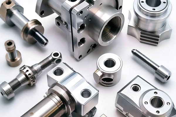
Automated equipment contains many non-standard structural components and precision functional parts. CNC machining can quickly produce prototypes with different materials and structures based on 3D drawings.
Equipment Structural and Mounting Parts
Equipment base plates, support frames, mounting plates, and connecting bases directly affect overall assembly relationships. During the prototype stage, dimensions and mounting positions need to be carefully verified.
- Mounting Plates and Bases: Verify hole positions, steps, reference surfaces, and equipment interfaces.
- Support Structures: Check installation space, rigidity, and overall assembly relationships.
- Connecting Bases and Fastening Parts: Confirm the positioning and connection methods between different modules.
Completing physical verification of structural parts early can help identify discrepancies between drawings and actual assembly in time.
Motion Mechanisms and Functional Parts
Sliders, bushings, adapters, fixtures, and transmission components in automated equipment often have strict dimensional and fit requirements, making CNC machining suitable for functional prototype verification.
- Shafts and Sleeves: Focus on verifying diameter, concentricity, and mating clearance.
- Fixtures and Locating Parts: Check positioning accuracy, clamping space, and ease of operation.
- Sliding and Transmission Parts: Pay attention to motion fit, mounting position, and surface quality.
After these parts are quickly machined into physical prototypes, their motion and assembly performance can be verified more intuitively.
How Can Automated Equipment Rapid Prototyping Shorten the Development Cycle?
The key to rapid prototyping is reducing waiting and rework during manufacturing, allowing design issues to be identified and corrected as early as possible.
Complete DFM Process Review Before Machining
Before formal machining, the structure should be reviewed against the 3D model and engineering drawings to determine whether it is suitable for CNC manufacturing.
- Check Machining Accessibility: Analyze tool access conditions for deep cavities, narrow slots, small holes, and complex surfaces.
- Optimize the Clamping Method: Reserve appropriate locating surfaces and clamping areas to reduce the difficulty of repeated setups.
- Distinguish Critical Dimensions: Avoid applying overly tight tolerances to every dimension and focus on features that actually affect assembly.
Resolving manufacturing difficulties in advance can reduce repeated modifications to programs and drawings during machining.
Match the Machining Method to the Part Structure
Simple plates and brackets can be machined using 3-axis CNC machines, while multi-sided structures can use 4-axis or 5-axis machining. Shaft-type parts can be produced through CNC turning. Selecting the appropriate machining equipment can reduce the number of setups and improve the positional relationship between complex features.
Establish a Prototype Inspection Process That Matches Tolerance Requirements
After the prototype is completed, critical dimensions and geometric tolerances should be inspected according to the overall assembly requirements, with appropriate measuring tools selected accordingly. Calipers and micrometers can be used for linear and external dimensions according to the drawings, while critical geometric features such as position, perpendicularity, concentricity, and complex profiles can be verified with coordinate measuring machines or specialized equipment. The results can then be used to adjust the design in a timely manner.
Control Prototype Deformation Caused by Machining Stress
For parts such as aluminum mounting plates, bases, and sliders that require substantial material removal, residual stress and machining deformation need to be considered during the prototyping stage.
- Distribute Machining Allowances Properly: Avoid removing large amounts of material in a single operation, which can cause significant stress release.
- Arrange Rough and Finish Machining: For thin-walled, large-sized, or high-precision parts, deformation can be controlled by separating rough machining from finish machining.
- Apply Stress Relief Based on Material Condition: For specific aluminum alloys and structures, aging or other stress-relief processes can be evaluated according to material condition, material removal volume, and accuracy requirements.
Proper control of machining stress can reduce warping after the part is removed from the fixture and dimensional changes during subsequent assembly.

How Can Rapid Prototyping Transition Smoothly to Mass Production?
After prototype verification is completed, the validated design needs to be converted into a stable production solution, with particular attention to tooling, cutting tools, programs, and inspection methods.
Standardize the Validated Machining Process
After prototype testing, the verified machining solution should be organized into a stable production process.
- Fix the Program Version: Retain the validated CNC programs and machining parameters.
- Define Machining Datums: Determine production clamping datums based on prototype verification results.
- Record Key Parameters: Organize cutting tools, cutting parameters, and machining sequences for repeatable production.
Complete process documentation can reduce the time spent on repeated trial and error during mass production.
Introduce Tooling During Small-Batch Trial Production
Dedicated fixtures do not necessarily need to wait until mass production. For parts requiring high repeatability in positioning, tooling solutions can be verified in advance during engineering trials or small-batch production.
| Development Stage | Stage Objective | Customer Focus | CNC Machining Task |
| First Article Prototyping | Verify structure and basic functions | Dimensions, assembly, space | Rapid 3-axis, 4-axis, and 5-axis machining |
| EVT Engineering Validation | Confirm engineering design feasibility | Function, critical dimensions, assembly relationships | Prototype machining and design adjustments |
| DVT Design Validation | Check design maturity | Tolerances, reliability, process optimization | Small-batch machining and process refinement |
| PVT Production Validation | Verify the production process | Tooling, inspection, yield, cycle time | Trial machining under production conditions |
| Mass Production | Maintain continuous delivery | Consistency, cost, lead time, quality | Standardized CNC batch production |
EVT, DVT, and PVT are commonly used stages in product development and production validation, although their specific definitions can vary depending on the project management approach. Bringing tooling, inspection, and production documentation into the trial and validation stages in advance can help reduce process risks after mass production begins.
Establish an Inspection Plan That Matches Batch Production
Mass production cannot rely entirely on first-article inspection. In-process inspection and final inspection should be established according to critical dimensions, production volume, and quality risks. For dimensions that affect assembly, inspection frequency can be increased to identify dimensional drift caused by tool wear or changes in clamping conditions.
What Capabilities Should Be Considered When Selecting a CNC Supplier for Automated Equipment?
For automated equipment manufacturers, whether a supplier can continuously support different development stages directly affects subsequent purchasing and production management.
Support Multiple Materials and Complex Structures
Automated equipment parts involve various materials, requiring cutting tools and processes to be matched according to material characteristics.
- Common Material Types: Automated equipment commonly uses aluminum alloys, stainless steel, carbon steel, and engineering plastics.
- Material and Process Matching: Different materials require different cutting tools and machining parameters.
- Flexible Process Adjustment: Suppliers need to adjust processes according to part structures rather than applying a fixed solution to every order.
Proper material and process matching is an important prerequisite for maintaining the quality and efficiency of automated equipment parts.
Maintain Stable Quality Control Capabilities
Batch-produced parts need to maintain consistency in dimensions, surface treatment, and assembly fit.
- Critical Dimension Inspection: Focus on dimensions that affect equipment assembly and motion.
- In-Process Quality Control: Monitor factors such as tool wear and changes in clamping conditions during production.
- Final Inspection: Complete final inspection according to drawings and order requirements and retain the corresponding records.
Stable quality control can reduce dimensional variation between batch-produced parts and minimize rework during final equipment assembly.
Respond Flexibly to Design Changes
Automated equipment often undergoes hole-position adjustments, structural optimization, and material changes during the R&D stage. Suppliers need the ability to quickly modify machining solutions. For parts that have not yet been fully finalized, small-batch machining can be used for verification first, followed by a gradual increase in production volume after the design is frozen. This approach can reduce the risk of excessive upfront investment.
From prototype development to mass production, automated equipment parts need to address process continuity, dimensional control, and production stability. TiRapid provides CNC milling, turning, and 3-axis to 5-axis precision machining services based on customer drawings, helping automated equipment parts transition from rapid prototyping to engineering trials, small-batch production, and mass production.