
A mold core is a precision mold component used to form internal features, recessed areas, holes, ribs, bosses, threads, and complex geometry in molded or cast parts. In injection molding, it works with the mold cavity to define the final part shape, dimensional accuracy, surface quality, and ejection behavior.
This guide explains what a mold core is, how it differs from a mold cavity, common core types, material options, design factors, CNC machining methods, inspection points, and how to choose the right mold core solution for your project.
What Is a Mold Core?
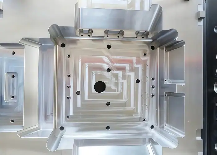
A mold core is the part of a mold that forms the internal or recessed features of a molded component. In many injection molds, the core is located on the moving side of the mold and works with the cavity side to shape the final plastic part.
For example, if a plastic housing has inner walls, screw bosses, ribs, through holes, snap-fit features, or recessed pockets, these areas are often created by the mold core. Any error on the core surface can transfer directly to the finished part, so accuracy and stability are important.
A mold core also affects cooling, shrinkage, part release, cycle time, surface finish, and tool life. A well-designed core helps reduce common molding problems such as sticking, deformation, flash, drag marks, sink marks, and dimensional variation.
Mold Core vs Mold Cavity
Mold core and mold cavity work together, but they serve different functions. The cavity usually forms the outer or visible surface of the molded part, while the core forms internal, recessed, or functional features.
In a typical injection mold, the cavity side is often called the A-side, and the core side is often called the B-side. The B-side usually contains the ejection system, so the part is often designed to stay on the core side after the mold opens.
This core and cavity arrangement affects appearance, draft direction, ejection marks, surface texture, wall design, and tooling cost. If the placement is not planned correctly, the part may stick to the wrong side or become damaged during ejection.
Main Functional Difference
The mold cavity mainly controls the external appearance of the part, including cosmetic surfaces, logos, textures, and visible details. These surfaces may require polishing, texture control, or special finishing.
The mold core mainly controls the inner geometry and functional areas. It may create bosses, ribs, holes, internal walls, threads, undercuts, and assembly features. These features often require precise machining because they affect fit and function.
For many plastic parts, the core side is less visible but more technically important. It may contain ejector pin marks, reinforcement ribs, and mounting structures, so engineers should decide early which side must remain cosmetic and which side can accept functional marks.
Part Release and Ejection
Part release is a key reason why mold core design matters. As plastic cools, it shrinks. If the part shrinks onto the core side, the ejection system can push it out in a controlled way.
If the part sticks to the cavity side instead, ejection becomes more difficult because that side may not have ejector pins. This can cause part damage, production delays, or mold modification.
Good core design uses proper draft, balanced ejection, suitable surface finish, and careful undercut control. These details help the part release smoothly and reduce molding defects.
Common Types of Mold Cores
Different part designs require different mold core structures. A simple molded cover may only need a fixed core, while threaded parts, side holes, undercuts, and deep internal features may need more complex core systems.
The right mold core type depends on part geometry, material shrinkage, production volume, tolerance, surface finish, and ejection method. A simple core is easier to manufacture and maintain, while a complex core can form advanced geometry but increases cost.
Fixed Mold Core
A fixed mold core stays in position during molding and forms standard internal features such as pockets, bosses, ribs, walls, and holes. It is the most common and cost-effective core type for parts without complex undercuts.
Fixed cores are reliable because they have fewer moving components. They are suitable for many high-volume production molds when the part includes proper draft and simple release geometry.
However, fixed cores cannot form features that lock the part in place. If the design includes side holes, internal threads, reverse angles, or undercuts, additional mechanisms may be required.
Insert Mold Core
An insert mold core is a removable or replaceable core component installed inside the mold. It is useful when only one area needs repair, polishing, material upgrade, or future design changes.
Insert cores are often used for small detailed features, logos, text areas, fragile sections, high-wear zones, or product variants. If a feature changes, the manufacturer can replace the insert instead of rebuilding the entire core.
The key requirement is accurate fitting and positioning. Poor insert alignment can cause flash, mismatch, dimensional errors, or visible parting marks on the molded part.
Side Core
A side core moves sideways to form features that cannot be released in the main mold opening direction. It is commonly used for side holes, slots, undercuts, clips, connectors, pipe fittings, and complex housing features.
Side cores can be driven by angled pins, mechanical slides, hydraulic cylinders, or other mechanisms. They expand design possibilities but also increase mold complexity, maintenance, and cost.
Before using a side core, engineers should check whether the feature can be redesigned with simpler geometry. If the feature is necessary, slide travel, locking strength, wear, cooling, and mold space must be reviewed.
Collapsible and Unscrewing Cores
Collapsible cores are used for internal undercuts, grooves, or threaded-like features that would otherwise trap the part. After molding, the core collapses inward so the part can be removed safely.
Unscrewing cores are used for molded threads. Instead of forcing the part off the thread, the mold rotates the core to release the part and protect thread accuracy.
Both solutions are useful for caps, fittings, connectors, medical parts, and fluid-handling components. However, they are more expensive and require careful design, precision machining, and regular maintenance.
Casting Core
In casting, a core creates internal cavities, hollow spaces, and channels inside metal castings. Sand cores, shell cores, and 3D printed cores are commonly used in foundry applications.
Unlike injection mold cores, casting cores are placed inside the mold before molten metal is poured. After solidification, the core is removed to leave the internal geometry.
Casting cores and injection mold cores are used in different processes, but their purpose is similar: they create internal features that cannot be formed by the outer mold shape alone.
Mold Core Materials
Mold core material selection affects tool life, machining difficulty, polishing quality, cooling performance, corrosion resistance, and total mold cost. The best material depends on production volume, molded material, hardness requirement, expected wear, surface finish, and budget.
Low-volume tooling may use aluminum or pre-hardened steel, while high-volume molds usually require stronger tool steels. Corrosive plastics, glass-filled resins, and high-temperature polymers may need stainless or hardened mold steels.
| Material | Main Advantages | Typical Use |
| P20 Tool Steel | Good machinability, toughness, and cost balance | General plastic injection molds |
| NAK80 | Good polishing and dimensional stability | Cosmetic and transparent plastic parts |
| S136 / Stainless Mold Steel | Better corrosion resistance and polishing ability | Medical, optical, and corrosive resin molds |
| H13 / 2344 Tool Steel | High strength, wear resistance, and heat resistance | Long-life and demanding production molds |
| Aluminum | Fast machining and good thermal conductivity | Prototype and low-volume molds |
| Copper Alloy Inserts | Fast heat transfer in hot spots | Deep ribs, thick sections, and cooling-critical areas |
Mold Core Design Considerations
Mold core design directly affects molded part quality, mold life, production stability, and manufacturing cost. A good core should form the required geometry, release the part smoothly, control cooling, resist wear, and stay dimensionally stable during repeated cycles.
Before machining the mold core, engineers should review part geometry, wall thickness, draft, shrinkage, undercuts, material flow, cooling, ejection, surface finish, and maintenance access.
Draft Angle
Draft angle is the slight taper added to vertical walls so the molded part can release from the core. Without enough draft, the part may stick, show drag marks, deform, or require excessive ejection force.
The required draft depends on part depth, plastic material, shrinkage, wall geometry, and surface texture. Textured surfaces usually need more draft than smooth surfaces because texture increases release friction.
Deep ribs, tall bosses, and long internal walls need special attention. These features often shrink tightly around the core and can become difficult to eject if the draft is too small.
Shrinkage Allowance
Plastic materials shrink as they cool. The mold core must include shrinkage allowance so the final molded part reaches the required dimensions after cooling.
Different plastics shrink at different rates. Filled materials may also shrink differently in different directions. This affects hole sizes, boss dimensions, wall thickness, assembly fits, and overall part accuracy.
For precision molded parts, material data, mold flow analysis, prototype testing, and trial molding can help refine shrinkage compensation before full production.
Cooling Design
Cooling affects cycle time, warpage, shrinkage, sink marks, and dimensional consistency. Poor core cooling can create hot spots, uneven shrinkage, and longer production cycles.
Cooling channels should be placed close enough to heat concentration areas while maintaining mold strength. Deep cores, narrow ribs, and thick sections may require special cooling methods or high-conductivity inserts.
Good cooling design improves both part quality and production efficiency. It should be planned during core design, not added after problems appear.
Ejection Design
Ejection design controls how the part is removed from the core. Common ejection methods include ejector pins, sleeves, stripper plates, air assist, or customized ejection structures.
Ejector locations should support the part strongly without causing cracks, stress marks, deformation, or unacceptable cosmetic marks. Ejector marks are usually placed on non-cosmetic or functional-acceptable surfaces.
Because the part often shrinks onto the core, the core side must be designed with realistic ejection force in mind. Proper draft, surface finish, and balanced ejection help reduce release problems.
Undercuts and Internal Features
Undercuts prevent the part from releasing in the normal mold opening direction. They may require side cores, lifters, collapsible cores, unscrewing mechanisms, or part redesign.
Internal threads, snap hooks, grooves, holes, and recessed features can all create undercut challenges. These features increase tooling cost and maintenance requirements.
When possible, designers should simplify undercuts, adjust parting lines, add draft, or modify geometry. If the feature is necessary, the core mechanism must be designed for stable production.
Surface Finish
The mold core surface finish affects the molded part surface, release behavior, friction, and cosmetic quality. A polished core may improve appearance and release, while a textured surface may require more draft.
For functional internal features, the core may need precise machining, EDM texture, polishing, or surface treatment. The finish should match the molded part requirement instead of being unnecessarily smooth.
Over-polishing non-critical areas can increase cost without improving performance. Critical surfaces should be clearly marked on the mold drawing or tooling specification.
How Mold Cores Are Manufactured?
Mold core manufacturing usually combines several precision processes. The exact workflow depends on material, hardness, geometry, tolerance, surface finish, and production volume.
A typical process may include material preparation, rough machining, heat treatment, CNC finishing, EDM, grinding, polishing, surface treatment, and inspection. Each step must be controlled because small core errors can affect every molded part produced later.
CNC Milling
CNC milling is one of the main methods for manufacturing mold cores. It creates core shapes, pockets, ribs, slots, shut-off surfaces, cooling areas, and complex 3D contours.
Tool selection and toolpath strategy are important for mold core machining. Roughing tools remove material efficiently, while finishing tools improve surface quality and dimensional accuracy.
For complex mold cores, 3-axis, 4-axis, or 5-axis CNC machining can reduce setups and improve alignment between features.

CNC Turning
CNC turning is used for round mold cores, pins, sleeves, threaded cores, cylindrical inserts, and shaft-like tooling components. It can produce accurate diameters, grooves, tapers, threads, and concentric features.
Turned mold core parts are common in caps, fittings, connectors, cylindrical housings, and molded parts with round internal features.
Additional grinding or polishing may be required when the core needs tighter tolerance, smoother surface finish, or better sealing performance.
EDM Machining
EDM is used for features that are difficult to machine with standard cutting tools. It is suitable for deep ribs, sharp corners, narrow slots, fine details, and hardened steel areas.
Sinker EDM uses custom electrodes to create detailed cavities and internal shapes. Wire EDM cuts precise profiles, inserts, slots, and openings.
EDM is especially useful after heat treatment because it can machine hardened steel without cutting force. However, the EDM surface may require polishing depending on part requirements.
Grinding, Polishing, and Surface Treatment
Grinding improves flatness, parallelism, perpendicularity, fit surfaces, and tight dimensions. It is often used for inserts, shut-off faces, precision plates, and hardened mold core components.
Polishing improves surface finish and can affect the appearance and release behavior of molded parts. It is important for transparent parts, cosmetic surfaces, sealing areas, and low-friction release.
Surface treatments such as nitriding, coating, or hardening may be used to improve wear resistance, corrosion resistance, or tool life. These processes should be planned together with tolerance requirements.
Mold Core Quality Inspection
Mold core inspection confirms whether the component meets design requirements before mold assembly and trial molding. Since the core directly affects every molded part, inspection is a critical part of tooling quality control.
Inspection may include dimensional measurement, surface finish checking, hardness testing, visual inspection, assembly fitting, cooling channel inspection, and trial mold feedback.
Dimensional Inspection
Dimensional inspection checks the size, position, depth, angle, and geometry of the mold core. Common tools include CMM, micrometers, pin gauges, bore gauges, height gauges, optical systems, and profile projectors.
Critical features may include core depth, hole location, insert fit, boss geometry, thread dimensions, shut-off surfaces, and alignment datums.
Accurate inspection helps confirm that the molded part can meet tolerance after shrinkage and trial adjustment.
Surface Finish Inspection
Surface finish inspection checks polishing quality, EDM texture, roughness, scratches, pits, burns, and tool marks. This is important because the mold core surface transfers directly to the molded part.
Functional surfaces may require roughness measurement, while cosmetic surfaces may require visual inspection or sample molding confirmation.
For transparent or high-gloss parts, the inspection standard should be agreed before finishing begins.
Hardness and Assembly Check
Hardness testing confirms whether the mold core reached the required condition after heat treatment. If hardness is too low, the core may wear quickly. If hardness is too high or uneven, cracking, polishing difficulty, or machining risk may increase.
Assembly inspection checks whether the core fits correctly with the cavity, inserts, slides, lifters, ejectors, and cooling system. Poor fitting can cause flash, mismatch, wear, or mold damage.
Trial molding is the final practical check. It verifies filling, cooling, ejection, surface quality, dimensional accuracy, and defect risks under real production conditions.
Common Mold Core Problems
Mold core problems can cause molding defects, production delays, higher maintenance cost, or mold damage. Many issues come from poor design, wrong material choice, machining errors, weak cooling, insufficient polishing, or inaccurate assembly.
Common problems include part sticking, core wear, corrosion, flash, sink marks, warpage, poor surface finish, broken core pins, and dimensional variation.
Part Sticking
Part sticking happens when the molded part does not release smoothly from the core. It may be caused by insufficient draft, rough surface finish, deep ribs, high shrinkage, poor ejection design, or excessive texture.
Sticking can cause drag marks, deformation, cracking, and production stoppage. Possible solutions include adding draft, improving polishing, adjusting ejector layout, changing texture direction, or modifying molding parameters.
Core Wear
Core wear occurs when repeated molding cycles, abrasive fillers, high pressure, or poor lubrication damage the core surface. Wear can change dimensions, create flash, reduce surface quality, and shorten mold life.
Glass-filled plastics and high-volume production increase wear risk. Harder mold steel, surface treatment, replaceable inserts, and better material selection can help reduce this problem.
Corrosion
Corrosion can happen when corrosive plastics, moisture, or poor storage conditions attack the mold core surface. Corrosion can damage the core and transfer defects to molded parts.
Stainless mold steel, protective coatings, proper maintenance, and correct storage can reduce corrosion risk. For corrosive resins, corrosion resistance should be considered during material selection.
Dimensional Variation
Dimensional variation may result from machining error, heat treatment distortion, poor cooling, shrinkage mismatch, mold wear, or unstable molding conditions.
For precision parts, both tooling tolerance and molded part tolerance should be reviewed together. Accurate CNC machining, stable heat treatment, proper cooling, and trial mold adjustment help control final dimensions.
Mold Core Applications
Mold cores are used in many industries where molded or cast parts need internal geometry, repeatable production, and stable performance. The specific core design depends on part size, material, volume, tolerance, and functional requirements.
In injection molding, mold cores are used for housings, caps, connectors, fittings, brackets, medical components, and consumer products. In casting, cores are used for hollow parts, fluid channels, manifolds, pump housings, and valve bodies.
Automation
Automation equipment often uses molded covers, cable guides, brackets, grippers, sensors, and fixture components. Mold cores help form mounting bosses, ribs, connector areas, and internal support structures.
Industrial Equipment
Industrial equipment may require housings, covers, fluid passages, handles, valve components, and structural plastic or metal parts. Mold cores help create internal geometry for assembly, strength, and function.
Electronics
Electronics products often need precise housings, connectors, battery compartments, buttons, and internal supports. Mold cores form screw bosses, snap fits, ribs, and internal walls while keeping cosmetic surfaces on the cavity side.
Robotics
Robotics components may include lightweight covers, sensor housings, cable routing parts, grippers, and precision internal structures. Mold cores help produce repeatable geometry for assembly and motion control systems.
Aerospace and Automotive
Aerospace and automotive parts often need lightweight structures, controlled dimensions, and reliable production quality. Mold cores can form internal features, channels, clips, housings, brackets, connectors, and fluid-related components.
Medical Devices and Consumer Products
Medical device parts may require clean geometry, precise features, smooth surfaces, and stable molding quality. Consumer products need both appearance and function, so mold cores often form internal assembly features while the cavity controls the visible surface.
FAQs
How do I know if my part needs a simple mold core or a complex core mechanism?
A simple fixed core is usually enough when the part has internal features that can release in the main mold opening direction. If the part has side holes, internal threads, snap features, reverse angles, or undercuts, it may need a side core, lifter, collapsible core, or unscrewing core.
How do you choose the right material for a mold core?
The right mold core material depends on the molding process, production volume, resin type, and expected tool life. Common choices include P20 for general-purpose molds, H13 for high-temperature applications, and stainless tool steels for corrosive environments. Factors such as wear resistance, toughness, machinability, thermal conductivity, and heat treatment requirements should also be evaluated to ensure stable molding performance and long service life.
Which mold core material is better for high-volume production?
For high-volume production, hardened tool steel, H13, 2344, S136, or other durable mold steels are often preferred. The best choice depends on resin type, wear risk, corrosion risk, polishing requirement, and expected mold life.
What machining methods are used for precision mold cores and inserts?
Precision mold cores and inserts are commonly made by CNC milling, CNC turning, EDM, wire cutting, grinding, polishing, and surface treatment. The best process depends on the core material, hardness, geometry, tolerance, surface finish, and functional features. For complex cores, a combination of CNC machining and EDM is often used to achieve accurate details, sharp corners, deep ribs, and stable mold fitting.
Conclusion
A mold core is an important tooling component that shapes internal features, supports part release, affects cooling, and controls final molded part quality. Good mold core design helps improve production stability, reduce defects, and extend tool life.
At TiRapid, we provide precision CNC machining for mold cores, mold inserts, and custom tooling components. Send us your drawings, 3D files, material, tolerance, heat treatment, and quantity requirements, and our team can help review the best machining solution for your project.
















