
CNC drilling is a precision machining process used to create accurate holes in metal and engineering plastic parts. It is common in brackets, housings, manifolds, fixtures, heat sinks, and assemblies where hole position, depth, thread quality, and burr control affect fit and reliability. This also makes quoting, machining, and inspection easier to control.
This guide explains how CNC drilling works, which hole-making operations are commonly used, how materials affect drilling quality, what design details engineers should control, how tolerances and inspection are handled, and what information to include when requesting CNC drilled parts. This should be confirmed early when the hole affects assembly or fit.
What Is CNC Drilling?
CNC drilling is a computer-controlled machining method that uses rotating cutting tools to create holes at programmed locations. The machine controls spindle speed, feed rate, tool path, retract height, and drilling depth, allowing repeated holes to be produced with stable accuracy across one part or a full batch. It supports stable production planning.
Unlike manual drilling, CNC drilling follows digital data from CAD drawings and CAM programs. This makes it suitable for bolt patterns, dowel holes, threaded holes, ventilation holes, fluid channels, and other features that must align with mating parts during assembly or final use. This helps balance accuracy, lead time, and machining cost.
CNC drilling is often combined with CNC milling, CNC turning, tapping, reaming, counterboring, countersinking, chamfering, and deburring. Combining these processes in one workflow reduces handling error, improves feature alignment, and helps produce finished precision parts efficiently. This is important for prototypes, small batches, and repeat orders.
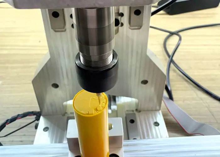
How Does CNC Drilling Work?
A CNC drilling project starts with a review of the drawing, 3D file, material, hole size, depth, tolerance, thread requirement, and surface finish. The machining plan then defines the tool sequence, workholding method, coolant strategy, drilling cycle, chip evacuation, and inspection approach. This reduces the risk of scrap, rework, and assembly problems.
Programming and Hole Position Control
CAD data defines the part geometry and hole features, while CAM software converts those features into machine instructions. The program controls coordinates, tool order, depths, retract moves, spindle speeds, feed rates, and cycles so each hole is produced in the correct position. This reduces the risk of scrap, rework, and assembly problems.
Good programming prevents avoidable errors in hole patterns and critical assembly features. Bolt circles, dowel holes, blind holes, cross holes, and threaded holes should be checked carefully because a small coordinate or depth error can affect how the finished part assembles. This is useful when the part must fit reliably with mating components.
For complex parts, drilling may be programmed together with milling or turning in the same setup. This improves alignment between holes and machined faces, reduces tolerance stack-up, and avoids extra handling caused by moving the part between different machines. This keeps the process controlled without adding unnecessary machining time.
Tooling, Workholding, and Coolant
Tool selection depends on material, hole diameter, depth, tolerance, surface finish, and thread requirement. Common tools include twist drills, spot drills, carbide drills, reamers, taps, thread mills, countersinks, and counterbores, each serving a different hole function. This is useful when the part must fit reliably with mating components.
Stable workholding keeps the workpiece from moving, vibrating, or bending during drilling. This is important for thin plates, soft plastics, small components, long parts, and tight hole patterns where clamping pressure or drilling force can change the final dimension. This keeps the process controlled without adding unnecessary machining time.
Coolant helps control cutting heat, flush chips, and extend tool life. It is especially useful when drilling stainless steel, titanium, deep holes, or materials that generate heat quickly, because trapped chips and high temperature can damage both the drill and the hole wall. This keeps the process controlled without adding unnecessary machining time.
Common CNC Drilling Operations
CNC drilling includes several related operations, not only simple hole making. Some parts need clearance holes, while others need threads, tight-tolerance bores, flat-bottom recesses, countersunk screw seats, or deep holes that require special cycles and stronger process control. This gives buyers and engineers a clearer path from design to quotation.
Basic and Deep-Hole Drilling
Standard drilling creates a cylindrical hole with a rotating drill bit. It is used for mounting holes, clearance holes, airflow holes, fluid passages, and general assembly features where the hole does not require a special finish or tight fit beyond normal machining tolerance. This helps TiRapid review manufacturability before quoting the project.
Spot drilling creates a controlled starting feature before the main drill enters the material. It helps prevent the drill from walking across the surface, which is useful for precise hole locations, angled surfaces, hard materials, and repeated hole patterns. It also improves consistency when the same part is ordered again later. It reduces production risk.
Peck drilling is used when holes are deep or chip evacuation is difficult. The drill enters the material in steps and retracts during the cycle, allowing chips to break and coolant to reach the cutting zone instead of packing tightly inside the hole. It is a small detail, but it can prevent costly production issues. It supports stable production planning.

Threading and Precision Hole Finishing
Tapping creates internal threads after the correct pre-hole is drilled. The tap drill size must match the thread size, pitch, material, and required engagement, because a hole that is too small can break the tap, while a hole that is too large can weaken the thread. This helps the supplier choose a stable process and avoid unnecessary rework.
Reaming improves hole diameter accuracy and internal surface finish. It is often used for dowel pin holes, locating holes, bearing fits, shaft fits, and precision assembly features that need tighter control than standard drilling can provide by itself. It also gives the finished part more predictable assembly quality. It supports stable production planning.
Counterboring creates a flat-bottom recess for socket head screws or bolt heads, while countersinking creates a conical recess for flat-head screws. Drawings should define diameter, depth, angle, and tolerance so fasteners seat correctly after machining. It should be reviewed before the quotation is finalized. It supports stable production planning.

CNC Drilling vs Reaming, Boring, and Tapping
CNC drilling is often the first step in creating a hole, but it is not always the final operation. Some parts need better diameter accuracy, smoother internal surfaces, accurate threads, or improved alignment after the initial hole is drilled. Understanding the difference between drilling, reaming, boring, and tapping helps engineers choose the right process before quoting.
| Process | Main Purpose | Best Used For |
| CNC Drilling | Creates the initial hole | Clearance holes, mounting holes, fluid passages, ventilation holes |
| Reaming | Improves hole size and surface finish | Dowel holes, pin holes, precision locating holes, H7 holes |
| Boring | Enlarges or corrects an existing hole | High-accuracy bores, bearing fits, aligned holes |
| Tapping | Creates internal threads | Screw holes, threaded inserts, assembly fasteners |
When Standard Drilling Is Enough?
Standard drilling is usually enough when the hole is used for general fastening, clearance, airflow, fluid passage, or non-critical assembly. In these cases, the hole does not need a very tight fit, and normal CNC drilling accuracy can often meet the functional requirement. This helps keep machining time and cost under control.
For simple holes, the main concerns are diameter, depth, position, burr control, and whether the hole is blind or through. If the part only needs screws to pass through or basic mounting points, extra finishing operations may not be necessary. A clear drawing note can help the supplier avoid over-processing the hole.
However, standard drilling should not be used as the final process for every hole. If the hole controls alignment, supports a shaft, holds a dowel pin, seals fluid, or affects repeatable assembly, the design may need reaming, boring, or a tighter inspection method. This should be reviewed before production starts.
When to Use Reaming or Boring?
Reaming is used when a drilled hole needs better diameter accuracy and smoother internal surface quality. It is common for dowel pin holes, locating holes, and precision assembly features where a standard drilled hole may be too rough or too loose for the required fit. The drilled hole is usually made slightly undersize first.
Boring is often used when the hole needs more accurate alignment, straightness, roundness, or position control. It can correct an existing hole and produce a more controlled bore for bearings, bushings, shafts, and precision mating parts. Boring is slower than drilling, but it gives better control for critical features.
If a hole has a specific fit requirement, such as H7, press fit, transition fit, or bearing fit, the drawing should show the tolerance clearly. This allows the supplier to choose drilling plus reaming, drilling plus boring, or another finishing method instead of assuming standard drilling is enough.
When to Use Tapping or Thread Milling?
Tapping is used after drilling to create internal threads for screws, bolts, or threaded fasteners. The pre-drilled hole must match the thread size and material condition, because an incorrect tap drill size can cause weak threads, oversized threads, or broken taps during machining. This is especially important for blind holes.
Thread milling can be a better option for larger threads, difficult materials, thin-wall parts, or high-value components where tap breakage would be costly. It also gives better control over thread depth and can sometimes create different thread sizes with the same tool family. The process may take longer but can reduce risk.
For threaded holes, the drawing should include thread size, pitch, usable thread depth, total hole depth, tolerance class, and whether the hole is blind or through. If coating or anodizing will be applied after machining, that should also be noted because finishing can affect the final thread fit.
CNC Drilling Design Tips
Good hole design makes CNC drilling faster, cleaner, and more cost-effective. Before production, engineers should review hole diameter, depth, spacing, wall thickness, edge distance, access direction, tolerance, thread details, and whether secondary operations are truly required. This helps the supplier choose a stable process and avoid unnecessary rework.
Hole Depth and Edge Distance
Very deep holes are harder to drill because chips are difficult to remove and the tool may deflect during cutting. Heat can also build inside the hole, reducing tool life and creating rough internal surfaces or inaccurate depth control in blind features. It improves control during first article inspection. It improves control during first article inspection.
A practical hole depth improves machining stability and reduces cost. If a deep hole is necessary, the drawing should clearly show full drill depth, usable depth, tolerance, bottom shape, and whether the hole is blind or through so the process can be planned correctly. This helps the supplier choose a stable process and avoid unnecessary rework.
Holes placed too close to an edge can weaken the part, create breakout, or reduce thread strength. Enough material around the hole improves strength, supports the drill as it exits the workpiece, and helps reduce burrs, cracking, deformation, and pull-out problems. This helps the supplier choose a stable process and avoid unnecessary rework.
Threads, Chamfers, and Tolerances
Threaded holes should show thread size, pitch, usable thread depth, total drill depth, and whether the hole is blind or through. Without this information, the supplier may not know how much thread engagement is required or how much tool clearance is needed. It improves machining control. This also makes quoting, machining, and inspection easier to control.
Counterbores, countersinks, spotfaces, chamfers, and deburring notes should also be specified clearly. These features affect fastener seating, appearance, assembly fit, and edge safety, especially when screws or pins are installed repeatedly. It reduces production risk. This should be confirmed early when the hole affects assembly or fit.
Tolerance should match the function of the hole. Clearance holes can often use general tolerances, while dowel holes, bearing holes, sealing features, and critical alignment holes may need reaming, boring, GD&T position control, or special inspection. This helps the supplier choose a stable process and avoid unnecessary rework. It improves machining control.
Materials and Applications for CNC Drilling
CNC drilling can be used for many metals and engineering plastics, but each material behaves differently during cutting. Hardness, toughness, heat resistance, chip formation, and work hardening affect tool choice, feed rate, spindle speed, coolant strategy, and inspection needs. This also makes quoting, machining, and inspection easier to control.
Metals and Engineering Plastics
Aluminum is one of the easiest and most common materials for CNC drilling. It cuts quickly, supports good hole quality, and is widely used for housings, brackets, plates, fixtures, heat sinks, and lightweight parts that need accurate mounting or assembly holes. This should be confirmed early when the hole affects assembly or fit. It reduces production risk.
Stainless steel, carbon steel, tool steel, and titanium require stronger process control than aluminum. Depending on hardness and heat sensitivity, they may need rigid setup, sharp tools, coolant, carbide drills, EDM, grinding, or slower cutting conditions. This supports better DFM review before machining begins. It supports stable production planning.
Engineering plastics such as POM, nylon, PTFE, PEEK, PPSU, Ultem, acrylic, and PVDF can also be drilled. Sharp tools, controlled clamping, and heat control are important because some plastics deform, burr, chip, melt, or crack around hole edges. This helps balance accuracy, lead time, and machining cost. It improves control during first article inspection.
Industry Applications
Automation and industrial equipment use CNC drilled holes for fixtures, brackets, grippers, sensor mounts, guide plates, housings, frames, valve bodies, pump parts, manifolds, and machine components that require repeatable assembly and stable alignment. This is important for prototypes, small batches, and repeat orders. It helps avoid avoidable rework.
Electronics and robotics parts may need drilled holes for heat sinks, enclosures, connectors, PCB fixtures, cable routing, joints, brackets, sensor mounts, grippers, and lightweight structures where hole accuracy affects assembly and motion performance. This gives the machinist a clearer basis for setup and inspection. It supports stable production planning.
Aerospace, medical, automotive, and powersports parts often require precise holes, clean edges, thread control, and reliable inspection. In these industries, drilling quality can affect safety, fit, service life, and acceptance of the final component. This reduces the risk of scrap, rework, and assembly problems. It supports stable production planning.
Tolerances and Quality Inspection
CNC drilling accuracy depends on machine condition, workholding, tool runout, material behavior, drilling depth, cutting parameters, and inspection method. General holes may need only standard tolerance, while dowel holes, bearing holes, threads, and sealing features need tighter control. This detail should be shown clearly on the drawing or RFQ.
Diameter, Position, and Depth
Hole diameter is affected by drill size, runout, tool wear, material behavior, and cutting heat. Standard drilling is suitable for many clearance holes, but tight fits may require reaming, boring, or another finishing operation to improve size and surface quality. This keeps the process controlled without adding unnecessary machining time.
Hole position affects assembly and alignment. For bolt patterns, dowel pins, and mating parts, position tolerance may be more important than diameter alone, so datum references and true position callouts should be shown clearly on the drawing. This is useful when the part must fit reliably with mating components. It supports stable production planning.
Blind hole depth and thread depth must be checked carefully because they affect fastener engagement and clearance. A blind threaded hole needs extra drill depth beyond the usable thread, so the drawing should not confuse total depth with usable thread depth. This helps protect both part function and final inspection results. It helps avoid avoidable rework.
Burr and Thread Inspection
Burrs are common at drilled hole edges, especially where the tool exits the material. Burr size depends on material, drill sharpness, feed rate, tool wear, support under the workpiece, and whether the hole breaks into another surface. This keeps the process controlled without adding unnecessary machining time. It supports stable production planning.
Inspection may use pin gauges, plug gauges, bore gauges, thread gauges, CMM, calipers, micrometers, or visual checks. Critical holes should have clear inspection requirements, especially when burrs, position, fit, or thread quality affect product function. This gives buyers and engineers a clearer path from design to quotation. It improves machining control.
Poor thread quality may come from wrong tap drill size, worn taps, poor chip evacuation, incorrect tapping speed, or insufficient blind hole depth. Thread gauges can confirm whether the finished thread meets the required standard before parts move to assembly. This helps TiRapid review manufacturability before quoting the project. It reduces production risk.
What to Include in a CNC Drilling RFQ
A clear RFQ helps the supplier quote accurately and avoid assumptions. For CNC drilling projects, provide 2D drawings, 3D CAD files, material grade, quantity, hole diameters, depths, tolerances, thread details, datum requirements, and surface finish expectations. This helps the supplier choose a stable process and avoid unnecessary rework.
You should also specify whether holes are blind or through, whether threads are required, and whether counterbores, countersinks, chamfers, spotfaces, or deburring are needed. For critical holes, include inspection requirements and mating part information. It is a small detail, but it can prevent costly production issues. It helps avoid avoidable rework.
If the part needs finishing after drilling, include that information early. Anodizing, passivation, plating, painting, or other coatings may affect hole size, thread fit, or assembly clearance, so the final process should be considered before machining starts. It helps avoid assumptions that may increase cost or delay delivery. It improves machining control.
FAQs
What is the difference between CNC drilling and CNC milling?
CNC drilling mainly creates holes with rotating drill tools, while CNC milling removes material to create pockets, slots, contours, flat surfaces, and complex shapes. Many precision parts use both processes in one setup so holes can align correctly with milled faces and other functional features. It should be reviewed before the quotation is finalized.
When does a drilled hole need reaming?
A drilled hole may need reaming when it requires tighter diameter tolerance, smoother internal finish, or a controlled fit for dowel pins, shafts, bushings, or precision assemblies. General clearance holes usually do not need reaming unless the drawing specifies a special tolerance or fit. It should be reviewed before the quotation is finalized.
Can CNC drilling create threaded holes?
Yes. CNC drilling creates the correct pre-hole, and tapping or thread milling creates the internal thread. The drawing should specify thread size, pitch, usable thread depth, total hole depth, and whether the hole is blind or through, so the supplier can choose the right threading method. It helps the supplier select the right tools and process.
Can CNC drilling be used for deep holes?
Yes. CNC drilling can produce deep holes, but the process often requires peck drilling cycles, specialized tooling, effective coolant delivery, and careful chip evacuation. Hole diameter, depth ratio, material type, and tolerance requirements all influence the machining strategy and the achievable hole quality. It helps reduce the risk of tool wear and drilling defects.
Conclusion
CNC drilling is a core machining process for accurate holes, threaded features, counterbores, countersinks, and precision assembly details. Good results depend on hole design, material behavior, tool selection, setup rigidity, cutting parameters, burr control, and inspection planning. This also makes quoting, machining, and inspection easier to control.
At TiRapid, we provide CNC drilling, CNC milling, CNC turning, tapping, reaming, and precision machining services for metal and engineering plastic parts. Send us your 2D drawings, 3D files, material requirements, quantity, and hole specifications, and our team can help review the best machining solution for your project. It helps avoid avoidable rework.
















