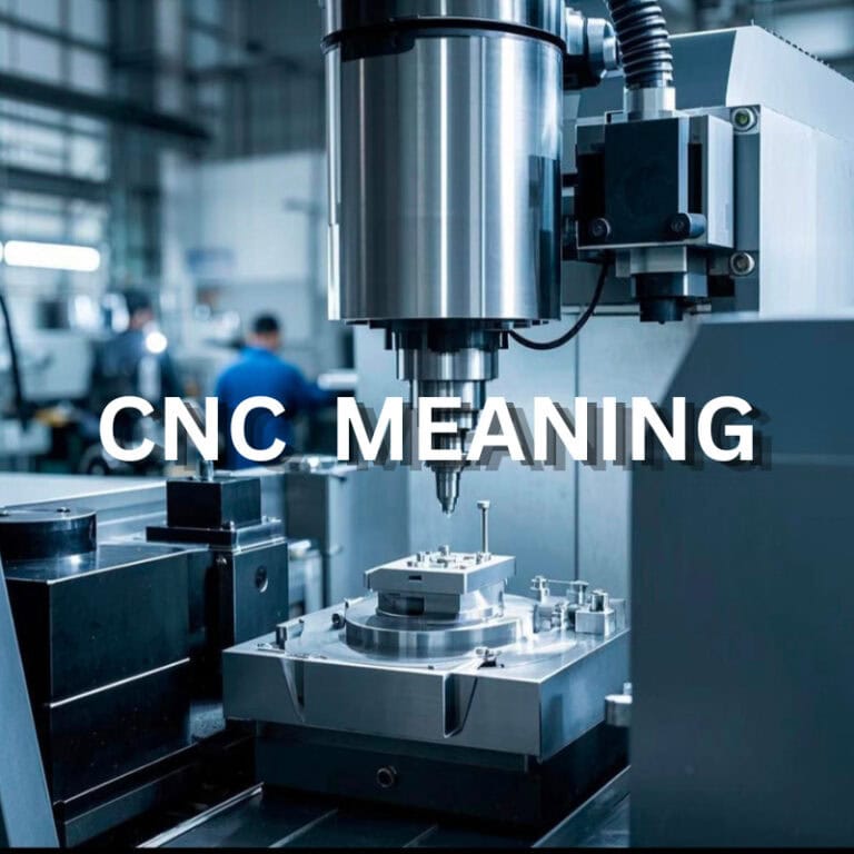
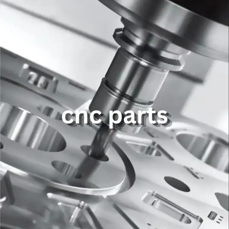
Ion implantation is a critical process in semiconductor manufacturing. The equipment must accurately implant specific ions into silicon wafers under controlled conditions. However, stable equipment performance depends on more than the core technology. The machining quality of internal chambers, mounting brackets, positioning components, and connecting structures also plays an important role. Dimensional deviations, uneven sealing surfaces, and residual burrs can all affect assembly and operation. For semiconductor equipment manufacturers, choosing the right CNC machining solution means achieving the required precision while balancing material performance, machining efficiency, and batch consistency.
Which Ion Implantation Equipment Parts Require CNC Machining?
Ion implantation equipment contains complex internal structures, with different components responsible for support, positioning, connection, and vacuum sealing. Machining is not just about matching the dimensions shown on a drawing. Each part must also perform reliably once installed in the equipment.
How Are Vacuum Chambers and Sealing Components Machined?
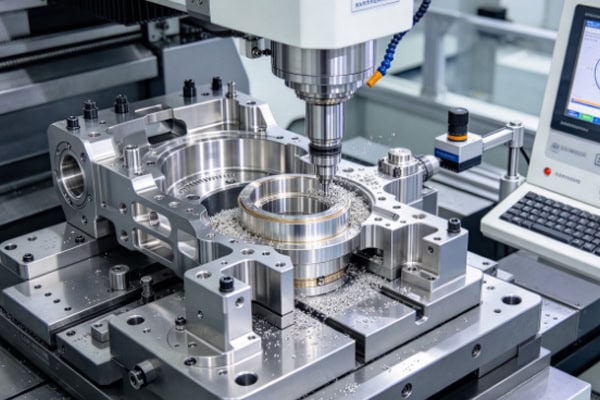
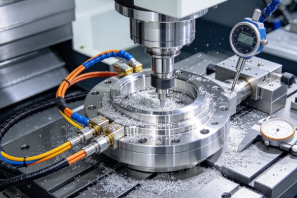
Vacuum chambers must maintain a stable working environment, and the dimensions of flanges, sealing grooves, and connection holes directly affect assembly performance. CNC machining can control critical dimensions according to engineering drawings while producing complex hole patterns and grooves. For sealing surfaces, flatness, surface roughness, and deformation after machining also require attention. A part may meet its dimensional specifications but still cause sealing problems during installation if these details are overlooked.
What Are the Machining Requirements for Wafer Positioning and Equipment Support Parts?
Positioning seats, mounting plates, support brackets, and clamping structures must maintain accurate positional relationships. Incorrect hole spacing or uneven mounting surfaces can increase assembly time and require additional adjustments. Precision CNC machining helps reduce errors caused by repeated setups, making it easier to maintain consistency across critical holes, stepped features, and mating surfaces.
What Are the Common CNC-Machined Parts Used in Ion Implantation Equipment?
| Part Type | Key Machining Requirements | Role of CNC Machining |
| Vacuum chambers and end covers | Flat sealing surfaces and dimensional stability | Produces complex cavities and sealing features |
| Positioning plates and mounting brackets | Accurate hole locations and reliable fit | Controls hole spacing and mounting dimensions |
| Precision connectors | Accurate interfaces and clean threads | Improves assembly compatibility |
| Cooling and auxiliary components | Accurate channel positions and clean surfaces | Machines internal passages and complex contours |
Different components have different structures and operating conditions, so the same machining process will not suit every part. Defining critical dimensions and functional requirements early can help reduce rework later.
How Should Materials and Machining Processes Be Selected for Ion Implantation Equipment?
Semiconductor equipment components have different material requirements. Some need to be lightweight, while others require higher strength, corrosion resistance, or dimensional stability. Choosing materials based on price alone can overlook important differences in machinability and performance under actual operating conditions.
Which Materials Are Suitable for Precision Ion Implantation Equipment Parts?
Aluminum alloys, stainless steel, and selected engineering plastics are all used in semiconductor equipment. The right choice depends on the component’s function, operating temperature, vacuum conditions, and surface treatment requirements.
| Machining Material | Main Properties | Typical Applications |
| Aluminum alloys | Lightweight, good thermal conductivity, easy to machine | Chamber structures, mounting plates, and support components |
| Stainless steel | High strength and good corrosion resistance | Flanges, connectors, and selected vacuum components |
| Engineering plastics such as PEEK | Good electrical insulation and suitability for selected chemical environments | Insulating components, positioning rings, and auxiliary parts |
Material grade is also important. Different grades of aluminum and stainless steel can have significantly different properties. If a part requires anodizing, passivation, or another surface treatment, these requirements should be confirmed before machining begins.
How Can CNC Machining Control Dimensional Errors in Complex Parts?
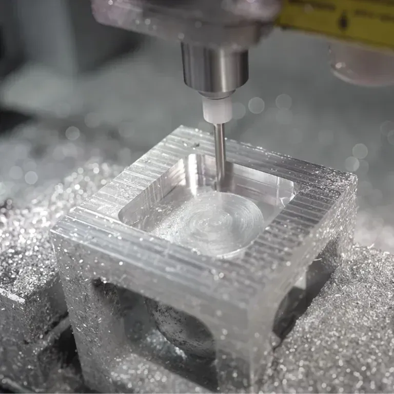
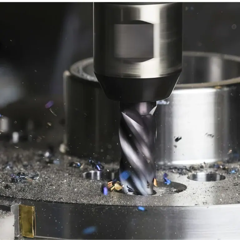
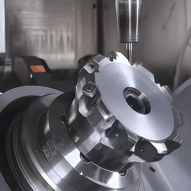
Ion implantation equipment components may contain deep holes, narrow slots, thin walls, and mounting surfaces in multiple directions. These features can be difficult to produce in a single operation using conventional methods. CNC milling, turning, and multi-axis machining allow processes to be planned around the part’s geometry, reducing unnecessary repositioning.
During machining, several factors deserve particular attention:
- Plan the machining sequence carefully: Remove most of the excess material before finishing critical dimensions to reduce the impact of cutting stress on the final shape.
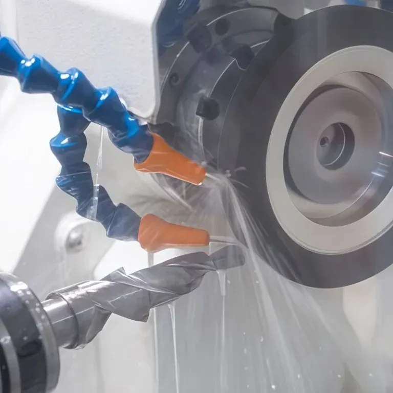
- Control workholding and tool conditions: Thin-walled components can deform, while excessive tool overhang may cause vibration. Clamping methods and cutting parameters should be adjusted to suit the part.
- Inspect functional dimensions: Sealing surfaces, positioning holes, and mating features need clearly defined inspection requirements rather than relying only on overall length, width, and height.
A well-planned process improves dimensional stability and reduces repeated machining, helping balance precision requirements with production efficiency.
What Surface Treatments Are Required for Ion Implantation Equipment Parts?
Some components require anodizing, passivation, or other specified surface treatments after CNC machining. The decision should account for more than appearance; operating conditions, corrosion resistance, dimensional tolerances, and surface cleanliness also matter. Since surface treatments can affect final dimensions, drawings should specify treatment areas and relevant requirements in advance, particularly for precision holes, mating surfaces, and sealing grooves. This helps prevent assembly problems after the parts have been finished.
How Can Quality Be Maintained and Costs Reduced in Ion Implantation Equipment Machining?
Semiconductor equipment parts often have complex geometries and demanding inspection requirements. If a problem is discovered only after machining is complete, the cost of rework can be much higher than the cost of checking the process earlier. Beyond the unit price, purchasing and engineering teams should consider process control, inspection standards, and whether prototypes can transition smoothly into batch production.
What Quality Checks Are Needed for Ion Implantation Equipment Parts?
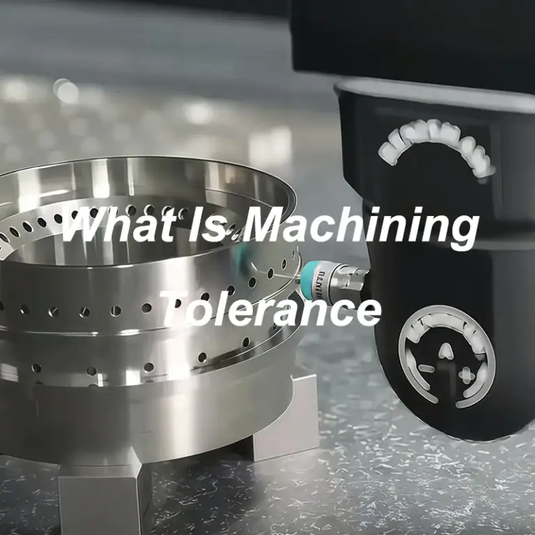
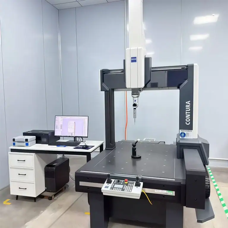
Different components require appropriate inspection methods. Standard dimensions can be checked with precision measuring tools, while complex contours and critical positional relationships may require coordinate measuring machine (CMM) inspection.
- Dimensions and positions: Check hole diameters, hole spacing, groove depths, and mounting dimensions against the engineering drawings.
- Surface quality: Inspect for burrs, scratches, machining marks, and defects on critical mating surfaces.
- Threads and sealing features: Verify thread specifications, thread depth, and sealing groove dimensions.
- Cleanliness and surface treatment: Confirm cleaning requirements and the condition of coatings or anodized layers according to the component’s intended use.
For components exposed to vacuum environments or subject to strict cleanliness requirements, deburring, cleaning, and packaging must not be overlooked. Inspection criteria should follow the engineering drawings and equipment requirements.
How Can Prototype Rework Be Reduced and Batch Consistency Improved?
Prototyping is not simply about confirming that a part can be manufactured. It is also an opportunity to verify dimensions, assembly fit, and the suitability of the machining process. Identifying issues early helps prevent the same errors from recurring during batch production.
- Provide complete 2D engineering drawings or 3D models, including critical tolerances and special requirements.
- Check prototype fit and assembly performance, then revise unsuitable dimensions or features when necessary.
- Maintain consistent key process parameters during batch production and carry out first-article and in-process inspections as planned.
If a component requires a special material, tight tolerances, or post-machining surface treatment, these details should be clarified before requesting a quote. Complete information makes it easier to assess machining difficulty, lead time, and cost.
What Factors Affect CNC Machining Costs for Ion Implantation Equipment?
Machining costs typically depend on material prices, part geometry, machining time, tolerance requirements, surface treatments, and order quantity. Components with complex structures, deep holes, or tight tolerances often require more detailed process planning and inspection. To manage costs, non-critical tolerances can be optimized where functional requirements allow, while material grades and finishing requirements should be confirmed early. Providing complete engineering drawings helps suppliers evaluate the manufacturing process more accurately and reduces the risk of quotation discrepancies or later changes.
Ion implantation equipment requires precision, structural stability, and appropriate cleanliness in its machined components. A suitable CNC machining solution can help semiconductor equipment manufacturers reduce assembly issues, improve part consistency, and move custom prototypes into batch production more smoothly. TIRAPID provides precision CNC machining services for custom components. Submit your engineering drawings, material grades, tolerance requirements, and order quantity to discuss a suitable machining solution and request a quote.