
CNC internal grooving is widely used in hydraulic components, bearing housings, precision sleeves, automotive parts, industrial connectors, and automation equipment. Internal grooves are commonly designed to accommodate retaining rings, sealing rings, locating rings, and other functional components. Groove width, depth, position, and surface quality all affect assembly accuracy and operational reliability. Compared with external grooving, internal grooving is more restricted by bore space, toolholder rigidity, chip evacuation, and tool accessibility. These limitations can lead to tool vibration, rough groove bottoms, dimensional deviations, and chip removal problems. For precision components requiring consistent batch production, selecting suitable internal grooving tools, optimizing cutting parameters, and establishing a standardized inspection process can improve machining consistency, reduce rework risks, and increase overall production efficiency.
Common Challenges and Accuracy Requirements in CNC Internal Grooving
CNC internal grooving is typically performed after a workpiece has been machined to create an internal bore. A dedicated internal grooving tool enters the bore and cuts the required groove. Because the tool must operate within a confined space, toolholder length, groove width, bore diameter, and groove position all influence machining difficulty. When machining deep bores or narrow grooves, a longer tool overhang reduces rigidity and increases the risk of vibration. Process planning should consider component geometry, material properties, drawing tolerances, and the intended assembly function rather than relying solely on groove width and depth to determine the machining method.
Why Is It Difficult to Maintain Accurate Internal Groove Dimensions?
Internal grooving requires precise control of groove width, groove depth, root diameter, and axial position. These dimensions are interconnected, and a deviation in any one of them may affect retaining ring installation, seal compression, or the positioning of mating components. In batch production of sleeves and hydraulic components, tool wear, machine thermal conditions, and changes in workholding position can also cause dimensional variations. Establishing clear dimensional references and inspection requirements during programming is therefore essential.
The following characteristics should be carefully controlled during precision internal grooving:
- Groove width: Select an insert that matches the drawing tolerance, accounting for actual insert width, tool wear, and dimensional changes during cutting.
- Groove depth: Establish cutting positions using a stable work coordinate system and internal bore datum to prevent the groove root diameter from becoming oversized or undersized.
- Axial position: Define the distance between the groove and reference features such as the end face or shoulder to reduce positioning errors.
- Groove root and sidewall quality: Optimize tool geometry and cutting conditions to minimize burrs, scratches, and visible chatter marks.
- Batch dimensional consistency: Use first-article inspection and in-process sampling to identify deviations caused by tool wear or changing machining parameters.
These control requirements should be managed together according to the engineering drawing. Groove width or depth alone cannot determine whether an internal groove meets all quality requirements.
How Do Toolholder Rigidity and Chip Evacuation Affect Machining?
Internal grooving tools must often extend deep into a workpiece, and longer overhangs generally reduce overall bending rigidity. Under excessive cutting loads, the toolholder may deflect elastically or vibrate, resulting in groove-root dimensional errors and reduced surface quality. At the same time, chips are difficult to remove from confined internal grooves. If chips repeatedly enter the cutting zone, they can scratch the groove surface, damage the cutting edge, or cause tool chipping.
Tool selection should account for bore diameter, groove width, groove depth, and material properties. For deeper internal grooves, unnecessary tool overhang should be minimized, and toolholders with sufficient rigidity should be selected. Coolant direction, chip clearance, and tool entry paths should also be checked during program development. Improving tool rigidity and chip evacuation can reduce vibration risks and improve dimensional and surface consistency.
Why Do Different Materials Require Different Internal Grooving Strategies?
Material properties directly affect cutting resistance, chip formation, tool wear, and surface finish. Aluminum alloys generally have relatively low cutting resistance but may produce long chips that wrap around the tool. Stainless steel is prone to work hardening, so cutting-edge geometry and machining parameters must be carefully matched. Alloy steel machining difficulty depends on material hardness and heat-treatment condition. Brass generally offers good machinability, although burr formation and groove dimensions still require control.
Cutting speed, feed rate, depth of cut, and cooling methods should be determined according to the material and component geometry. The same set of parameters should not be applied indiscriminately to all metals. Before batch production, trial cutting should verify groove width, groove depth, chip evacuation, and tool wear. This helps establish stable process parameters and reduces quality variations during production.
How to Optimize CNC Internal Grooving Tools and Machining Processes
The efficiency and quality of internal grooving depend on the interaction between tooling, cutting parameters, toolpaths, and machine condition. Suitable tooling must reach the target location while maintaining sufficient rigidity. Appropriate cutting parameters control cutting loads, while a well-designed program helps prevent tool collisions, repeated cutting, and unnecessary movements. For precision internal grooves, process optimization should balance dimensional accuracy, groove surface quality, tool life, and cycle time rather than relying solely on higher cutting speeds to improve productivity.
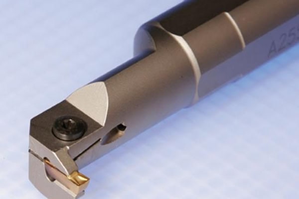
How to Select the Right CNC Internal Grooving Tool
Internal grooving tools should be selected according to the minimum bore diameter, groove width, groove depth, material, and dimensional tolerances. The insert width must satisfy the groove geometry, while the toolholder dimensions must provide both internal accessibility and adequate structural rigidity. An oversized toolholder may not fit into the target position, whereas an excessively thin toolholder or long overhang can lead to vibration and deflection. For special groove profiles, the tool geometry must also be checked to ensure that the groove root and sidewalls can be machined completely.
The following conditions should be evaluated when selecting tooling:
- Toolholder dimensions: Ensure that the tool can enter the minimum bore diameter with sufficient clearance for movement.
- Insert width: Match the insert to the specified groove width and tolerance. Multi-pass machining may be necessary for certain groove geometries.
- Cutting-edge geometry: Select suitable cutting geometry according to the groove root radius, sidewall profile, and material.
- Toolholder rigidity: Minimize unnecessary overhang to reduce vibration and elastic deflection.
- Chip evacuation design: Evaluate chip formation, coolant direction, and the path for removing chips from the bore.
- Tool life: Select suitable tool materials and coatings based on the workpiece material and production volume.
After tool selection, verify tool clamping, cutting-edge position, and the actual machining envelope on the machine. Confirm that the tool can enter the bore safely and complete the entire cutting path.
How to Optimize Cutting Parameters and Toolpaths
Internal grooving parameters should be adjusted according to material, tool dimensions, toolholder overhang, and groove geometry. Excessive feed rates can increase tool loads and vibration, while unsuitable cutting speeds may accelerate wear or create unstable chips. For narrow or deep grooves, a suitable multi-pass cutting strategy can prevent excessive material removal in a single operation.
During program development, carefully check the tool entry path, cutting start point, retract direction, and safe clearance positions. When a groove requires multiple passes, define the stock allowance for each pass and prevent chip accumulation from causing repeated cutting. During finishing, maintain stable cutting conditions to minimize variations in groove-root dimensions and surface patterns.
In production, trial machining can be used to record cutting parameters, cycle time, and tool wear before further adjustments are made based on measurement results. Once validated, the program and parameters should be documented in standardized process instructions to improve efficiency and consistency for repeat orders.
How to Reduce Burrs, Vibration, and Tool Wear
Burrs at groove entrances, scratches on groove roots, chatter marks, and tool chipping are common internal grooving problems. These defects may result from dull tools, excessive cutting loads, insufficient toolholder rigidity, poor chip evacuation, or unsuitable retract paths. The actual cutting conditions should be investigated for each defect rather than attempting to solve every problem simply by reducing the feed rate.
- Reduce burr formation: Optimize cutting-edge geometry and entry and exit paths, and apply suitable deburring operations when required.
- Minimize machining vibration: Shorten toolholder overhang, verify clamping rigidity, and adjust parameters according to actual cutting loads.
- Improve chip evacuation: Optimize coolant direction and prevent chips from remaining in the groove and being cut repeatedly.
- Control tool wear: Maintain tool-life records and replace tools before wear exceeds acceptable limits.
- Improve surface finish: Inspect cutting-edge condition, cutting parameters, and machine stability to prevent scratches and visible chatter marks on the groove root.
- Maintain machining safety: Simulate or safely verify the program before production and check for potential interference between the tool, workpiece, and fixture.
Combining defect records with dimensional inspection results helps identify the underlying causes more accurately and supports continuous process improvement. For batch production, a standardized response procedure for machining abnormalities can reduce downtime and repeated setup adjustments.
Quality Inspection and Custom Sourcing Guide for CNC Internal Grooving
Quality acceptance for precision internal grooves requires more than verifying groove width and depth. Depending on the engineering drawing, inspection may also need to cover axial position, groove-root diameter, profile, burrs, and surface condition. Different grooves serve different functional purposes. Sealing grooves must accommodate seal installation requirements, retaining ring grooves must position retaining rings correctly, and lubrication grooves may have specific width, depth, and surface requirements. Defining critical technical specifications before requesting a quotation helps machining suppliers develop more suitable process plans and reduces the risk of rework.
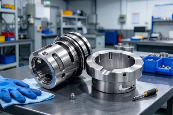
How to Inspect Internal Groove Dimensions and Surface Quality
Internal groove inspection requires suitable measuring tools based on groove dimensions, position, and geometry. Standard calipers are generally unsuitable for verifying every internal groove feature, particularly narrow grooves in deep bores or grooves with tight root-diameter tolerances. Components with demanding requirements may need specialized gauges, internal measuring instruments, groove-width gauges, or other professional inspection equipment.
Inspection should confirm whether groove width, groove depth, root diameter, and axial position meet the drawing requirements. For critical functional grooves, burrs, groove-root surface condition, and assembly fit should also be checked. Results should be recorded in first-article inspection reports or in-process quality documentation as a reference for subsequent batch production.
If dimensions consistently drift in the same direction, the manufacturer should inspect tool wear, tool-nose compensation, coordinate settings, and machine thermal conditions. Early corrective action helps prevent the accumulation of nonconforming parts.
How to Choose a Precision CNC Internal Grooving Supplier and Obtain an Accurate Quote
When selecting a CNC machining supplier, buyers should confirm that the supplier has precision internal boring capabilities, suitable internal grooving tools, reliable inspection facilities, and consistent batch production management. In addition to comparing unit prices, buyers should evaluate process feasibility, prototyping lead times, delivery reliability, material sourcing, and inspection documentation. For components with complex geometry or tight tolerances, the supplier’s engineering evaluation capability can directly affect project costs and delivery schedules.
Prepare the following technical information before requesting a quotation:
- 2D engineering drawings and 3D CAD models
- Material grade and heat-treatment requirements
- Bore dimensions, groove width, groove depth, and axial position tolerances
- Groove root radius and special profile requirements
- Surface roughness and deburring requirements
- Prototype quantity, batch quantity, and expected order frequency
- Inspection reports and delivery standards
Complete documentation helps suppliers evaluate tool accessibility, machining sequences, fixture requirements, and inspection methods. It also supports more accurate quotations and lead-time estimates. For ongoing supply projects, sample validation is recommended before the production process is approved for volume manufacturing.
TiRapid provides CNC turning and precision CNC machining services and can evaluate manufacturing feasibility based on part drawings, materials, dimensional tolerances, and production quantities. For components with internal grooves, precision bores, and special assembly requirements, buyers can submit complete CAD documentation and critical dimensional specifications during the quotation stage. This allows the engineering team to evaluate suitable machining sequences, tooling strategies, and quality-control requirements.
By selecting appropriate internal grooving tools, optimizing cutting parameters, improving chip evacuation and workholding, and implementing standardized dimensional inspection, manufacturers can improve the accuracy and batch consistency of CNC internal grooving. For hydraulic components, precision sleeves, bearing assemblies, and automation equipment parts, clearly defining groove functions and drawing tolerances is essential for stable machining and reliable assembly.
















