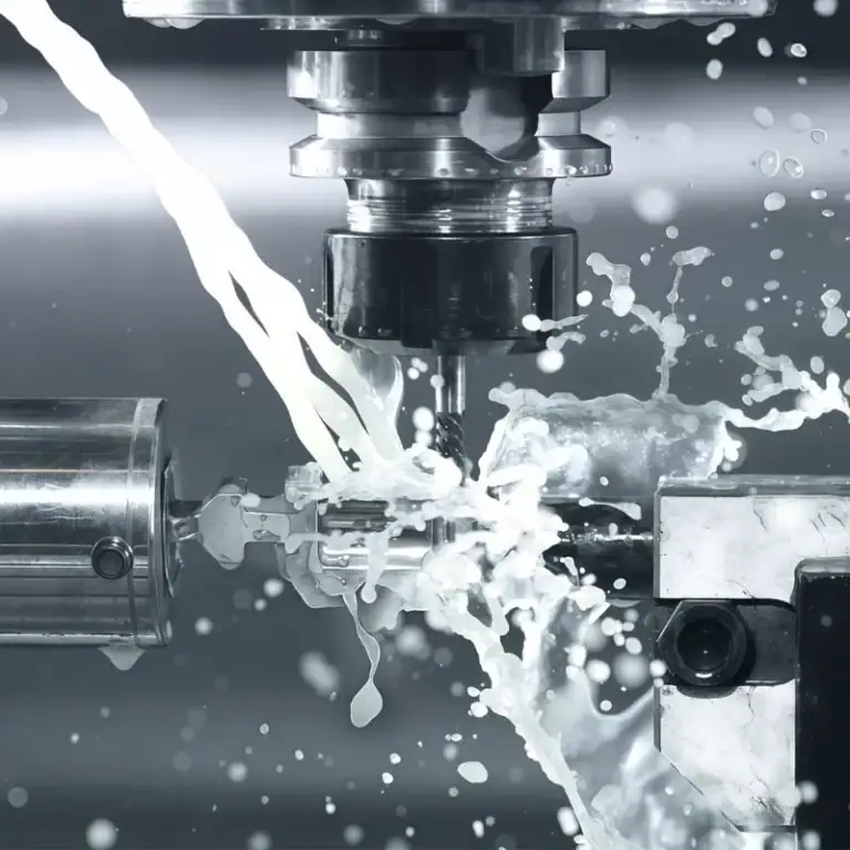
Complex fluid components are commonly used in hydraulic systems, pneumatic equipment, industrial pumps and valves, fluid control devices, and automated machinery. Typical parts include valve bodies, fluid fittings, manifold blocks, pump housings, nozzles, and pipeline connectors. These components often feature internal flow passages, intersecting holes, sealing grooves, threaded interfaces, and irregular curved surfaces. During machining, manufacturers must not only ensure accurate external dimensions but also control the positions of internal passages, hole diameter tolerances, and sealing performance at connection points. CNC machining uses programmed tool movements to achieve precision cutting of complex structures.
Depending on the structural complexity of the components, manufacturers can choose three-axis, four-axis, or five-axis CNC machining centers. Three-axis machining is suitable for relatively simple fluid components, while four-axis machining can handle multi-sided machining features and circumferential structures. Five-axis machining is more suitable for components with complex curved surfaces, angled passages, and multi-directional machining requirements. Selecting the appropriate number of machining axes helps reduce repeated setups, improve machining accuracy, and enhance the quality of complex flow passages. Therefore, the specific CNC equipment should be selected based on part drawings, machining operations, and structural characteristics.
Three-Axis CNC for Basic Fluid Components
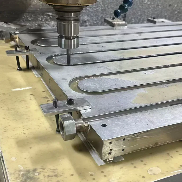
Three-axis CNC machining primarily relies on three linear motion axes, X, Y, and Z, to control tool positioning. It can perform plane milling, drilling, tapping, boring, and certain cavity machining operations. For fluid components with regular structures and a limited number of machining surfaces, three-axis equipment can generally meet basic dimensional accuracy and surface quality requirements. For example, conventional hydraulic valve blocks, straight-through fluid fittings, and simple pipeline connectors mainly involve flat surfaces, straight holes, and threaded holes. Three-axis CNC machining can complete most of these operations.
Common Machined Parts
Standard hydraulic valve blocks: These mainly require the machining of mounting surfaces, vertical oil passages, threaded interfaces, and positioning holes. They are suitable for step-by-step drilling and milling operations.
Fluid connection fittings: Common structures include external threads, internal threads, central through-holes, and end-face sealing grooves. Three-axis machining can meet conventional production requirements.
Simple pump housing components: For pump housings with relatively few internal structures and regular external shapes, three-axis equipment can be used to machine flat surfaces and hole positions.
When a component requires holes to be machined in several different directions, three-axis equipment generally requires multiple adjustments to the workpiece position. As the number of setups increases, the relative positioning accuracy between holes also needs to be controlled more strictly.
Four-Axis CNC for Multi-Surface Flow Passage Machining
Four-axis CNC machining adds one rotary axis to the three linear motion axes. Depending on the machine configuration, this rotary axis is commonly designated as the A-axis, B-axis, or C-axis. The A-axis rotates around the X-axis, the B-axis rotates around the Y-axis, and the C-axis rotates around the Z-axis. Typical four-axis setups include CNC rotary tables, rotary indexing units, and other fourth-axis attachments. These configurations allow the workpiece to rotate to different positions for multi-sided machining. The equipment can perform milling, drilling, and tapping at different angles, reducing the need for multiple setups and repeated workpiece repositioning during conventional machining. Complex fluid components often require oil inlets, oil outlets, mounting holes, and connection interfaces on different surfaces. If only three-axis equipment is used, multiple setups may be necessary to complete all hole positions. Four-axis CNC machining can adjust the workpiece angle through a rotary table or indexing unit, allowing the cutting tool to reach different machining surfaces.
Typical Applications of Four-Axis Machining
Multi-channel hydraulic manifold blocks: Different oil passage interfaces on multiple sides can be machined in succession, making it easier to control the positional relationships between holes.
- Cylindrical valve bodies: These are suitable for machining circumferentially distributed connection holes, positioning grooves, and threaded interfaces.
- Multi-face fluid fittings: Intersecting holes, side holes, and connection structures can be machined at different angles.
- Irregular pump and valve components: For parts with multiple machining surfaces, four-axis equipment can reduce the number of workpiece setups and improve process continuity.
Four-axis CNC machining is particularly suitable for fluid components with multiple machining surfaces, circumferential hole positions, or lateral flow passages. If the internal passages also contain complex inclination angles, conventional four-axis equipment may still require changes to the workpiece setup position to complete certain special structures.
Five-Axis CNC for Highly Complex Fluid Components
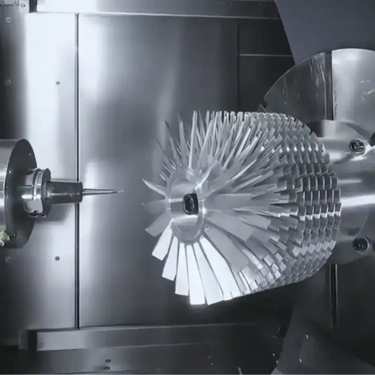
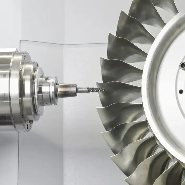
Five-axis CNC machining typically adds two rotary motion axes to the three linear motion axes of X, Y, and Z. The two rotary axes are commonly configured as A, B, or C axes, depending on the machine structure. The tool or workpiece can adjust its orientation in multiple directions, allowing the cutting tool to approach complex machining areas from different angles. For fluid components with inclined passages, spatially intersecting holes, complex curved surfaces, and irregular shapes, five-axis CNC offers strong machining capabilities. By planning toolpaths appropriately, manufacturers can reduce repeated setups and complete more machining operations from different directions in a single setup.

Which Complex Structures Are Suitable for Five-Axis Machining?
Multi-Angle Inclined Passages
Some hydraulic valve bodies and fluid control components contain multiple connection passages in different directions, such as inclined oil holes, intersecting flow passages, and inlet and outlet interfaces positioned at different angles. These passages must not only meet the specified hole diameters and depths but also maintain accurate spatial positioning to prevent problems such as hole misalignment or restricted flow connections. Five-axis CNC machining can adjust the relative orientation of the tool and workpiece, allowing the cutting tool to approach machining areas from different directions. This makes it easier to perform milling, drilling, and finishing operations on inclined holes and their surrounding structures. At the same time, reducing repeated setups helps control positional errors between different passages and improves machining consistency for complex fluid components.
Complex Curved Surface Structures
Some pump housings, fluid distributors, and special valve bodies have irregular external shapes, with certain areas featuring curved transition surfaces, inclined machining surfaces, and irregular contours. These structures place high demands on cutting direction and tool movement paths. When using traditional three-axis equipment, multiple adjustments to the workpiece position may be required to complete all machining operations. Five-axis equipment can dynamically adjust tool orientation according to changes in the surface geometry, helping maintain a more appropriate cutting position throughout the machining process. This reduces problems such as localized overcutting, tool marks on the surface, and machining interference. For fluid components with complex contours, continuous toolpath control can also improve surface smoothness, ensuring that the part geometry, connection areas, and transition structures better meet the requirements of engineering drawings.
Multi-Directional Sealing Structures
Complex fluid components may have multiple sealing end faces, annular grooves, and inclined connection surfaces. Five-axis machining can reduce workpiece repositioning and help maintain better positional accuracy between different structures. However, five-axis CNC does not mean that all internal flow passages can be machined directly. Deep holes, enclosed passages, and special intersecting flow channels usually require additional processes, such as deep-hole drilling, specialized cutting tools, cross-drilling, and other machining techniques.
Internal Passage Deburring and Cleaning
During the machining of hydraulic valve bodies and manifold blocks, intersecting drilled holes may generate burrs at internal passage intersections. These burrs can restrict fluid flow or become detached during operation, potentially contaminating the hydraulic system and affecting the performance of valves and pumps. Therefore, internal deburring and cleaning are important post-machining processes.
Depending on the component structure, material, and machining requirements, manufacturers can select suitable deburring methods:
Abrasive Flow Machining (AFM): This process uses abrasive media flowing through internal passages to remove burrs and improve the edges of intersecting holes and difficult-to-reach areas.
High-Pressure Water Jet Deburring: High-pressure water jets are directed toward specific internal passage areas to remove burrs and machining residues. The pressure and flow parameters need to be adjusted according to the component structure.
Mechanical Deburring: Specialized tools and suitable mechanical methods can be used to remove accessible burrs from holes and connection areas.
After deburring, fluid components should undergo thorough cleaning to remove residual chips, abrasive particles, cutting fluids, and other contaminants. Internal cleanliness inspection is also necessary to verify that the passages meet the specified cleanliness requirements before final assembly or delivery.

How to Determine the Number of CNC Machining Axes for Complex Fluid Components?
Choosing between three-axis, four-axis, and five-axis CNC machining should not depend solely on the overall size of the component. It also requires a comprehensive evaluation of machining positions, passage directions, structural complexity, and dimensional tolerances shown in the engineering drawings. Particular attention should be paid to internal fluid passages, including whether the cutting tool can enter the machining area smoothly and whether different passages contain spatial intersections or inclined connections. For deep holes, enclosed flow passages, and special internal cavities that are difficult for cutting tools to reach directly, manufacturers must also consider specialized tools or auxiliary machining processes to ensure that production meets the component’s design requirements.
What Should Be Considered When Selecting CNC Equipment?
Number of machining surfaces: If the component mainly requires machining on one or two planes, three-axis machining can be considered. If multiple sides contain machining features, four-axis or five-axis equipment may be more suitable.
Spatial structure of flow passages: Straight passages are generally easier to machine, while inclined passages and spatially intersecting structures require more flexible tool movement capabilities.
Workpiece clamping and positioning requirements: When multiple hole positions have strict positional relationships, reducing the number of setups helps control repeated positioning errors.
Machining accuracy requirements: Equipment and processes should be selected according to the drawing tolerances for hole diameters, hole spacing, coaxiality, perpendicularity, and sealing surfaces.
Frequently Asked Questions
Q1: Must complex hydraulic valve blocks be machined using five-axis CNC?
Not necessarily. If a hydraulic valve block mainly consists of vertical holes, horizontal holes, and conventional threaded interfaces, three-axis or four-axis equipment can also complete the machining. Five-axis CNC is more worth considering when the component contains numerous inclined machining surfaces, complex spatial structures, or special curved surfaces.
Q2: Can four-axis CNC machine complex fluid manifolds?
Yes. Four-axis CNC can generally meet the machining requirements of manifolds with multiple side interfaces, circumferential hole positions, and certain angular variations. However, if internal passages need to be machined from multiple complex directions, five-axis equipment or other auxiliary processes may be required.
Q3: Can five-axis CNC complete all machining operations for fluid components in a single setup?
Not necessarily. Five-axis equipment can reduce the number of setups, but deep holes, enclosed flow passages, and special internal cavities may still require other equipment or machining methods. Specific operations should be determined according to the component structure and tool accessibility. Post-machining operations such as deburring, cleaning, and internal cleanliness inspection may also be necessary.
CNC Machining Axis Selection for Different Fluid Components
The appropriate CNC machining configuration depends on the geometry, machining accessibility, and accuracy requirements of each fluid component.
Three-Axis CNC: Suitable for standard hydraulic valve blocks, simple fluid fittings, straight-hole connectors, and basic pump housing components.
Four-Axis CNC: Suitable for multi-sided manifolds, cylindrical valve bodies, and components with circumferential holes or multiple side interfaces.
Five-Axis CNC: Suitable for complex hydraulic valve bodies, irregular fluid control components, inclined passage structures, and parts with complex curved surfaces.
Conclusion
Complex fluid components generally need to meet requirements for internal flow passage accuracy, interface dimensions, sealing structures, and machined surface quality. Three-axis CNC can satisfy the machining requirements of basic structures, four-axis CNC is more suitable for multi-sided machining features and circumferential structures, while five-axis CNC is designed for complex components that require the cutting tool to approach machining areas from multiple directions. In actual production, machining processes must be developed based on 3D models, engineering drawings, passage layouts, and machining tolerances. The selection of equipment should also consider tool accessibility, workpiece clamping methods, and the complexity of internal structures. By properly arranging drilling, milling, boring, tapping, deburring, cleaning, and inspection operations, manufacturers can improve dimensional consistency and internal cleanliness.
For products such as fluid control valve bodies, hydraulic manifolds, and precision pump housings, choosing the appropriate CNC machining configuration is only one part of the manufacturing process. The coordination of machining operations, post-processing procedures, and quality inspections is equally important. A well-planned manufacturing process helps maintain positional accuracy between internal passages, ensures reliable sealing performance, and reduces the risk of residual machining contaminants. Selecting suitable CNC equipment and supporting processes ultimately helps manufacturers achieve a reasonable balance between machining efficiency, positioning accuracy, product quality, and manufacturing costs.