
CNC machining of complex plastic parts is an important manufacturing method in modern precision manufacturing. It is widely used in medical equipment, semiconductor equipment, automation machinery, aerospace, high-end electronic products, and other industries. Compared with ordinary plastic components, complex structural parts usually feature thin walls, deep cavities, multiple holes, irregular curved surfaces, and high-precision fitting requirements, which place higher demands on machining technology and process control. During actual production, material selection, machining path design, tool matching, and clamping methods directly affect the final machining results. If the process planning is unreasonable, problems such as dimensional deviations, deformation, reduced surface quality, or even part scrapping may occur.
Preparation Before CNC Machining of Complex Plastic Parts
Machining complex plastic parts is not simply a matter of inputting a program into a CNC machine and starting cutting. Sufficient preparation must be completed before machining begins. Since there are many types of plastic materials and different structural parts require different machining methods, preliminary analysis determines whether the subsequent machining process can proceed smoothly. Proper preparation can reduce problems during machining while improving part accuracy and production efficiency.
Analyze the Structural Characteristics of the Part
Complex plastic parts usually have structural features that ordinary components do not have, such as:
- Deep-hole structures;
- Thin-wall areas;
- Precision fitting surfaces;
- Multi-directional machining positions;
- Irregular curved surfaces.
These structures directly affect tool movement and machining difficulty. For example, when machining a plastic component with deep grooves and thin-wall areas, it is necessary to consider not only whether the tool can reach the machining position but also how to prevent deformation caused by cutting forces. If the thin-wall area lacks sufficient support during machining, dimensional changes may still occur during later inspection even if the machining dimensions initially meet requirements. Therefore, before machining, the part structure should be analyzed through a 3D model to determine in advance which areas require special tools, auxiliary supports, or adjustments to the machining sequence.
Select Suitable Plastic Materials
Different plastic materials have different machining characteristics, and material selection directly affects the machining strategy.
Common engineering plastics include:
POM (Polyoxymethylene): Good dimensional stability, suitable for precision components;
PA (Nylon): Good wear resistance but prone to moisture absorption;
PEEK: Excellent high-temperature resistance and chemical resistance;
PC: High transparency but prone to stress during machining;
ABS: Good machinability and wide range of applications.
If material properties do not match the working environment, the finished part may fail to meet actual application requirements. For example, if a component needs to operate under high temperatures for a long period but ordinary plastic is selected, the machining process may proceed smoothly, but deformation may occur during actual use. Therefore, before machining, the material should be selected based on the part’s strength requirements, temperature conditions, wear resistance requirements, and working environment.
Develop a Machining Process Plan
Complex parts usually require multiple machining steps to complete. They often go through rough machining, semi-finishing, finishing, necessary adjustments, and inspection procedures to gradually achieve the dimensional accuracy, surface quality, and assembly requirements specified in the design drawings.
Common processes include:
- Rough machining to remove excess material;
- Semi-finishing to adjust dimensions;
- Finishing to achieve accuracy;
- Surface treatment to improve performance.
A reasonable machining sequence can reduce deformation caused by internal stress release. For example, when machining large plastic plates, machining directly to the final dimensions in one step may cause warping after internal stresses are released. Therefore, staged machining methods should be used to gradually bring the part to the required design specifications.
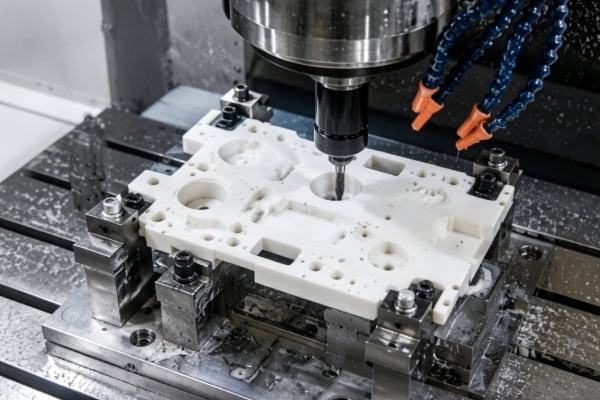
CNC Machining Process for Complex Plastic Parts
The machining process of complex plastic parts needs to be planned according to equipment capabilities, material characteristics, and part structures. Compared with simple components, complex parts require more attention to tool paths, cutting conditions, and dimensional control during machining to ensure that every processing step remains stable.
Develop the CNC Machining Program
The machining program determines the tool movement path and is an important factor affecting machining quality. It not only determines the tool movement sequence and cutting methods during processing but also directly affects the dimensional accuracy, surface finish, and overall machining efficiency of the part. Whether the program is properly written often determines whether the subsequent machining process can proceed smoothly. Therefore, before formal machining begins, the tool path design, feed parameters, and cutting sequence must be repeatedly checked to avoid machining deviations or material waste caused by programming errors.
Program design needs to consider:
- Tool movement routes;
- Cutting sequence;
- Machining allowance;
- Spindle speed and feed parameters.
Complex curved-surface parts usually require CAM software to generate 3D machining paths. The tool paths must be planned comprehensively according to surface changes, tool dimensions, machining allowances, and machine movement ranges. By optimizing tool paths through layering, zoning, and sequence adjustments, the tool can cover the target area more smoothly during machining, reduce repeated cutting and idle movements, improve machining efficiency, and help improve curved-surface quality while reducing the difficulty of subsequent finishing work.
If the tool path design is unreasonable, it may result in:
- Increased machining time;
- Repeated tool cutting;
- Reduced surface quality.
An excellent tool path design can not only reduce idle running and unnecessary movements, improving overall machining efficiency, but also allow the tool to maintain a more stable cutting condition. This effectively reduces vibration, minimizes tool wear, and further improves part surface quality and dimensional accuracy.
Select Suitable Machining Tools
Plastic machining places higher requirements on cutting tools. Tools must not only have sufficiently sharp cutting edges but also provide good wear resistance, chip evacuation performance, and cutting stability. Since plastics are prone to problems such as tool adhesion, heat buildup, burr formation, and surface scratches during machining, improper tool selection can directly affect part dimensional accuracy and appearance quality. Therefore, in actual machining, suitable tool types and cutting parameters should be selected according to material type, part structure, and machining accuracy requirements to ensure a more stable and efficient process.
Common cutting tools include:
- Single-flute milling cutters;
- Two-flute milling cutters;
- Ball nose cutters;
- Finishing tools.
Sharp cutting tools can reduce material compression and lower cutting heat. For example, when machining materials such as acrylic and PC that are prone to heat generation, insufficiently sharp tools may cause melting and tool adhesion. For high-strength materials such as glass-fiber-reinforced plastics, tools with better wear resistance are required to ensure machining stability.
Control Deformation During Machining
During CNC machining, complex plastic parts are often affected by factors such as relatively low material rigidity, uneven wall thickness, and unstable cutting force distribution. These factors can cause deformation, especially in thin-wall structures, deep cavities, and unsupported areas, where problems such as warping, dimensional deviations, and reduced surface accuracy are more likely to occur.
Common control methods include:
- Reducing the amount of material removed in each pass;
- Adding auxiliary supports;
- Optimizing clamping methods;
- Using staged machining processes.
For thin-wall structural parts, it is usually necessary to retain certain support structures or machining allowances during the early machining stages. Through staged cutting and gradual adjustment, these supports can be removed during the final stage. This method effectively improves overall part rigidity during machining and reduces deformation, vibration, and dimensional deviations caused by cutting forces, clamping forces, or material stress release, thereby improving machining stability and final part accuracy.

Process Technologies
Complex plastic part machining relies not only on CNC equipment accuracy but also on material characteristics and machining experience. Since plastic materials vary greatly in hardness, toughness, heat resistance, and dimensional stability, machining parameters cannot simply be standardized. Instead, process strategies must be adjusted according to part structure, material type, and machining requirements. Proper application of machining technologies can effectively solve common problems such as deformation, vibration, poor surface quality, excessive burrs, and dimensional deviations.
Especially when machining thin-wall parts, deep-cavity parts, and irregular curved-surface components, insufficient control over cutting speed, feed rate, clamping method, and tool selection can easily affect part accuracy and appearance quality. Therefore, only by combining equipment performance, process design, and practical machining experience can manufacturers better ensure the stability and final quality of complex plastic part machining.
High-Speed Precision Cutting Technology
Plastic materials are generally suitable for high-speed cutting methods. Since plastics usually have lower hardness than metals, properly selected spindle speed and feed parameters can not only improve machining efficiency but also reduce compression and friction between the tool and material, thereby lowering the possibility of burrs, tool adhesion, and poor surface finish. For plastic parts requiring high dimensional accuracy and appearance quality, high-speed cutting often provides more stable machining results.
High-speed machining can:
- Improve machining efficiency;
- Reduce cutting resistance;
- Improve surface quality.
However, high-speed machining does not mean unlimited increases in spindle speed. Adjustments must be made according to material type, tool geometry, and part size.
For example:POM can generally be machined at higher cutting speeds, while high-performance plastics such as PEEK require more stable machining conditions.
Multi-Axis Machining Technology
Some complex plastic parts require machining from multiple directions. They may require not only milling, slotting, and drilling on flat surfaces but also precision machining of side surfaces, inclined surfaces, and curved areas. Because these components have complex structures, traditional three-axis equipment often requires multiple setups and repeated repositioning, which can increase positioning errors and machining time.
Traditional three-axis machines may require multiple setups, while five-axis machining can:
- Reduce the number of setups;
- Improve positioning accuracy;
- Machine complex curved surfaces.
For example, complex products such as aerospace components and medical structural parts can achieve smoother continuous curved-surface machining through multi-axis processing.
Precision Inspection Technology
After complex parts are machined, strict inspection and quality verification are required. Inspection usually includes dimensional accuracy, geometric tolerances, surface roughness, and actual assembly performance of critical fitting areas. When necessary, tools such as coordinate measuring machines, calipers, and micrometers are used for verification. Through comprehensive inspection, potential issues such as machining deviations, burrs, deformation, or surface defects can be identified promptly, ensuring that the final parts meet design requirements and application standards.
Common inspection methods include:
- Coordinate measuring machine (CMM) measurement;
- High-precision caliper inspection;
- Micrometer measurement;
- Surface roughness testing.
Inspection confirms whether dimensions meet design requirements and prevents defective parts from entering the assembly stage.
Methods to Improve the Processing Quality of Complex Plastic Parts
The processing quality of complex plastic parts is affected by multiple manufacturing stages. It is not only related to equipment accuracy, tool condition, and process parameter settings, but also closely connected with operator experience, on-site management, and process control capabilities. Due to the characteristics of plastic materials, such as thermal sensitivity, easy deformation, and relatively low rigidity, improper processing operations can easily lead to dimensional deviations, rough surfaces, excessive burrs, or local warping. Therefore, establishing a stable, standardized, and repeatable processing workflow is very important. Through systematic management of preparation before machining, monitoring during machining, and inspection after machining, production risks can be effectively reduced, rework and scrap rates can be minimized, part consistency and batch stability can be improved, and overall production efficiency and product quality can also be enhanced.
Optimize Machining Parameter Settings
Different plastic materials require different machining parameters. It is not possible to simply apply the same spindle speed, feed rate, and cutting depth to all materials. Since different plastics vary significantly in hardness, toughness, thermal conductivity, and thermal deformation characteristics, targeted adjustments must be made according to material properties during machining. Only by continuously optimizing parameter settings based on material performance can the machining process become more stable and achieve higher dimensional accuracy and surface quality.
The following parameters need to be adjusted:
- Spindle speed;
- Feed rate;
- Cutting depth;
- Cooling method.
Proper parameters can reduce:
- Material melting;
- Tool vibration;
- Burr formation;
- Dimensional deviation.
During machining, parameters should be continuously optimized according to actual cutting performance, material condition, and changes in part structure, rather than using the same set of data permanently. Because different batches of materials may have differences in hardness, toughness, and thermal stability, while tool wear, machine operating conditions, and environmental temperature can also affect final machining results. Therefore, during actual production, it is necessary to continuously monitor surface quality, dimensional accuracy, and cutting stability, and adjust key parameters such as spindle speed, feed rate, and cutting depth in time. Only through repeated testing and dynamic optimization can the machining quality and production efficiency of complex plastic parts be better ensured.
Improve the Workholding Method
Complex plastic parts usually have relatively low rigidity, and the parts themselves are more likely to experience elastic deformation when subjected to external forces. Therefore, the workholding method directly affects machining stability, dimensional accuracy, and surface quality. If the clamping force is too high, it may damage the workpiece surface or cause local deformation during machining. If the clamping force is too low, the part may move under cutting forces, affecting the machining path and final dimensions. Therefore, during actual machining, an appropriate clamping method should be selected according to part structure, material characteristics, and machining requirements, while ensuring uniform force distribution, accurate positioning, and sufficient support.
Common methods include:
- Vacuum suction;
- Custom fixtures;
- Soft jaw clamping;
- Auxiliary supports.
Proper workholding can reduce part movement and improve machining accuracy.
Strengthen Post-Processing After Machining
After machining, some plastic parts usually require a series of post-processing procedures to further improve their appearance quality, dimensional stability, and service performance. Common post-processing methods include deburring, chamfering, polishing, cleaning, and necessary surface finishing. These processes can not only improve edge smoothness and reduce interference during assembly but also make part surfaces smoother and more attractive, meeting higher application requirements.
Common treatments include:
- Deburring;
- Polishing;
- Sandblasting;
- Surface cleaning.
These treatments can improve part appearance and enhance usage performance.
Common Questions
What machining accuracy can be achieved for complex plastic parts with CNC machining?
The machining accuracy of complex plastic parts depends on the material, equipment performance, part structure, and machining process. Ordinary plastic parts can usually achieve an accuracy of around ±0.05mm. After optimizing the process and using precision equipment, some parts can reach an accuracy level of ±0.01mm to ±0.02mm. For precision plastic components used in medical equipment, semiconductor equipment, and automation systems, accuracy needs to be controlled comprehensively based on material stability and inspection methods.
Conclusion
CNC machining of complex plastic parts is a manufacturing technology that requires a high level of process control. Only by combining material characteristics, structural features, equipment performance, and machining experience can stable and reliable processing results be achieved. With the continuous growth of demand for lightweight, high-precision, and corrosion-resistant components in the manufacturing industry, the application range of plastic CNC machining is also expanding. For plastic parts with complex structures and high precision requirements, only by establishing scientific machining processes and continuously optimizing process details during actual production can machining efficiency be improved, scrap rates be reduced, and parts be ensured to meet the requirements of different application scenarios.
















