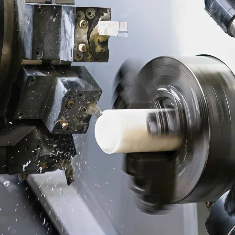
CNC thread turning is widely used in the manufacturing of mechanical fasteners, automotive components, hydraulic fittings, industrial pipe fittings, precision shafts, and automation equipment parts. Thread profiles, pitch, diameter, and surface quality directly affect assembly accuracy, connection strength, and service life. For businesses sourcing custom metal threaded components, selecting suitable machining processes, cutting tools, and inspection methods can reduce dimensional deviations, burrs, and thread damage while improving batch consistency. CNC thread turning uses computer-controlled tool movements to produce accurate threads and supports a wide range of internal and external thread specifications. Understanding machining principles, common defects, and quality control methods helps manufacturers optimize production, reduce rework costs, and make informed purchasing decisions for custom CNC turned parts.
CNC Thread Turning Principles
CNC thread turning uses a numerical control system to synchronize spindle rotation with tool feed, allowing the cutting tool to create a continuous helical thread profile. During machining, spindle speed, thread pitch, tool position, and cutting depth must remain properly coordinated. Compared with conventional external turning, thread turning requires more precise programming, tool positioning, and cutting sequences. Even small errors can affect the final assembly performance. For precision components requiring consistent batch delivery, a well-planned machining process and inspection workflow are equally important.
External and Internal Threads
External threads are commonly used on bolts, threaded shafts, connecting rods, and pipe fittings. They are typically produced by cutting the outside surface of a workpiece with an external threading tool. Internal threads are used in nuts, valve bodies, sleeves, and threaded holes, requiring internal threading tools or other suitable tooling based on the bore diameter. These two thread types have different tooling, workholding, and inspection requirements, so the machining process should be selected according to the component design.
- External thread turning: Control the major diameter, minor diameter, pitch, and thread profile. Ensure that tool entry and withdrawal do not damage the functional thread length. For long shaft components, workpiece vibration and clamping stability must also be considered to prevent periodic marks on the thread surface.
- Internal thread turning: Check the pilot hole diameter, hole depth, tool-bar rigidity, and chip clearance. When machining small bores, excessive tool overhang and chip accumulation can affect stability. Select an appropriate tool-bar size and ensure sufficient access to the machining area.
- Precision thread machining: Components with strict mating requirements must meet the specified dimensions, functional thread length, and applicable tolerance class. After machining, suitable thread gauges can verify whether the component meets the assembly requirements.
Clearly identifying thread types, operating conditions, and technical specifications helps machinists determine the appropriate tooling, programming method, and inspection standards while reducing rework.
Thread Pitch and Profile Specifications
Thread pitch is the axial distance between corresponding points on adjacent thread forms. Thread specifications also include nominal diameter, thread angle, hand, and tolerance class. Metric threads, Unified threads, and pipe threads follow different standards and cannot be assumed to be interchangeable based on appearance alone. An incorrect specification can cause assembly difficulties, loose connections, or inadequate sealing performance, even when the thread surface appears properly machined.
Before machining, manufacturers should verify the thread designation on the engineering drawing and confirm the required specification, tolerance, and functional length. For custom components that must fit other parts, internal and external thread standards should be checked for compatibility. For hydraulic systems, pipe connections, and sealing assemblies, the thread standard and sealing method must also be clearly defined to prevent confusion between thread fit and sealing requirements.
Common CNC Thread Turning Defects
Thread quality is affected by tool condition, cutting parameters, machine stability, program settings, and material properties. Common defects include incorrect pitch, incomplete thread profiles, rough surfaces, burrs, and dimensional deviations. These problems can increase rework time and affect assembly efficiency and connection reliability. A clear defect inspection process helps machinists identify the causes early and prevent nonconforming parts from entering subsequent operations.

Incorrect Thread Dimensions
Thread major diameter, minor diameter, or pitch diameter deviations can result in excessively tight fits, loose connections, or threads that cannot be assembled correctly. Common causes include tool wear, incorrect tool compensation, programming errors, and unsuitable measurement methods. During batch production, dimensional deviations may gradually increase as the tool wears. Without timely inspection, these changes can affect an entire production run.
- Check tool compensation: Verify tool position and offset values to ensure that the actual tool-tip position matches the programmed settings. After replacing an insert or resetting a tool, review the relevant parameters to prevent dimensional deviations.
- Verify the machining program: Check the thread pitch, cutting depth, starting position, and thread length against the engineering drawing. For new components or modified programs, perform a simulation and trial cut before beginning full production.
- Control machining allowance: Plan roughing and finishing operations carefully to prevent excessive material removal during the final cutting passes. For precision threads, confirm dimensions through trial machining and avoid making excessive parameter adjustments at once.
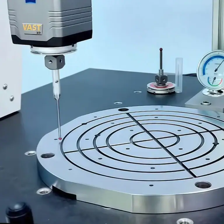
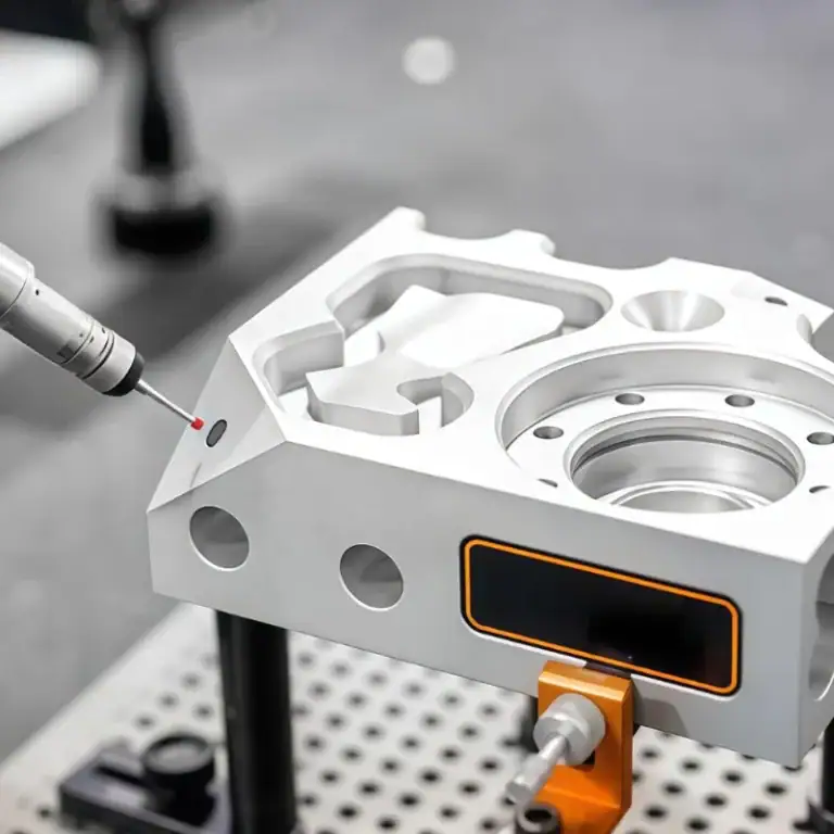
- Perform dimensional inspections: Use thread ring gauges, thread plug gauges, or suitable specialized measuring equipment according to the thread type. For components with specific tolerance requirements, follow the inspection method defined by the engineering drawing rather than judging quality solely by how tightly the threads fit together.
Program verification, trial machining, and staged inspections help identify dimensional deviations early, reduce material waste, and prevent defective components from reaching assembly.
Rough Thread Surfaces and Burrs
Scratches, tearing, burrs, and damaged thread crests may result from worn cutting edges, tangled chips, insufficient coolant, or unsuitable cutting conditions. When machining materials such as stainless steel, inappropriate cutting parameters may also cause work hardening and reduced surface quality. Chips that repeatedly contact finished thread surfaces can leave visible marks and affect both appearance and fit.
To address these problems, inspect the cutting edge, chip evacuation system, and coolant supply. Select cutting tools and parameters suited to the workpiece material. Tool paths at the thread entry and withdrawal positions should be planned carefully to avoid damaging functional threads. For materials that produce long chips, appropriate chip-breaking strategies and chip clearance can reduce interference during machining.
Deburring must also be controlled carefully to avoid changing thread dimensions or damaging the profile. After machining, remove residual chips from the thread grooves and inspect the crests, roots, and end transitions to ensure that the component can be assembled correctly.
How to Improve CNC Thread Turning Accuracy
Consistent thread quality requires accurate programming, suitable cutting tools, and reliable workholding. Machinists should develop the process according to material properties, thread specifications, machine capabilities, and order quantities, then verify the setup through trial machining and inspection. For complex components or applications requiring tight tolerances, evaluating tool accessibility and chip evacuation before production can reduce process adjustments later.
Select Suitable Threading Tools
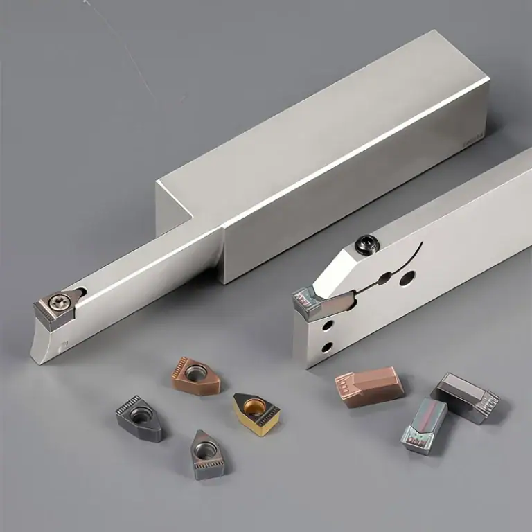
Threading tool geometry, insert profile, material grade, and cutting-edge design affect machining stability and finished quality. When selecting a tool, confirm that it supports the required thread standard, pitch, and workpiece hardness. Tool orientation and center height must also be correct to prevent profile deviations, uneven wear, and poor surface finish.
- Carbide threading inserts: Suitable for many common metal machining applications. Select the insert grade and geometry according to the cutting conditions and material. Wear resistance, cutting-edge strength, and chip control should all be considered.
- Internal threading tools: Choose the tool-bar dimensions according to the pilot hole diameter, hole depth, and available machining space. Excessive overhang can increase vibration. For deep internal threads, ensure that chips can escape without creating excessive cutting loads.
- External threading tools: Maintain stable insert positioning and verify tool center height to reduce thread profile deviations. Keep tool overhang within reasonable limits to maintain rigidity.
- Specialized threading tools: For unusual profiles or non-standard threads, confirm tool specifications and machining feasibility against the engineering drawing. Trial machining may be necessary to verify the thread profile, dimensions, and assembly fit before production.
Suitable tooling improves thread quality and machining stability while reducing additional costs associated with tool changes, process adjustments, and rework.
Optimize Cutting Parameters and Cutting Passes
Spindle speed, synchronized feed, cutting depth, and the number of passes must match the machine capabilities and workpiece material. Excessive cutting loads can damage tools, cause vibration, or produce incomplete thread profiles. Incorrect settings can also affect cycle time and surface quality. Distributing material removal across appropriate cutting passes helps reduce tool loads and improve process stability.
Before machining, confirm that the CNC system supports the required threading cycle and verify that spindle encoder feedback, synchronization control, and program commands are suitable. For deep threads or difficult-to-machine materials, a multi-pass strategy can distribute the cutting load more effectively. Specific cutting parameters should follow tool manufacturer recommendations and be validated through trial machining.
During batch production, monitor tool wear and first-piece dimensions. Adjust tool compensation when necessary to maintain consistent thread dimensions throughout the production run.
Thread Machining Requirements for Different Materials
Material hardness, toughness, thermal conductivity, and chip characteristics all influence thread machining performance. Even when the same thread specification is used, different materials may require different tools, cutting parameters, and cooling strategies. Adjusting the process to suit the material helps improve productivity and reduce profile defects, burrs, and dimensional deviations.

Aluminum Alloy and Brass Threads
Aluminum alloys offer good machinability and are commonly used for lightweight structural components, connectors, and automation equipment parts. During machining, attention should be paid to chip adhesion and burr formation. Sharp cutting edges and effective chip evacuation help maintain stable cutting conditions. For thin-walled aluminum components, excessive clamping force should be avoided to prevent deformation that could affect thread fit.
Brass is commonly used for valves, pipe fittings, and precision connectors. The machining strategy should be selected according to the alloy grade, part geometry, and surface finish requirements. For small threaded components, tool condition and workpiece positioning directly affect finished dimensions. After machining, inspect thread ends for burrs and verify that the component can engage smoothly with its mating part.
For high-volume connector production, stable workholding and consistent tool conditions help reduce dimensional variations between batches.
Stainless Steel and Carbon Steel Threads
Stainless steel thread machining requires careful control of work hardening, cutting temperature, and tool wear. Using inserts suitable for the material, maintaining stable cutting conditions, and removing chips promptly help produce complete thread surfaces. Avoid allowing the tool to rub excessively against the same surface, as this can reduce surface quality and shorten tool life. For components with demanding specifications, establish an appropriate inspection frequency according to the engineering drawing.
Carbon steel is widely used for mechanical connectors, shafts, and industrial fastening components. Cutting parameters should be selected according to the steel grade, hardness, and thread specification. Components requiring reliable connections should undergo thread inspection and any specified surface treatments.
If a component requires heat treatment or coating, evaluate how subsequent processing may affect thread dimensions, mating clearance, and surface conditions before finalizing the machining plan.
How to Choose a Custom CNC Thread Turning Supplier
When sourcing custom threaded components, supplier experience, equipment capabilities, and quality control procedures all affect the final result. Buyers should evaluate whether a supplier can interpret engineering drawings accurately, develop an appropriate machining process, and perform inspections according to agreed specifications. For repeat orders, the supplier’s ability to maintain consistent batch quality, communicate technical issues promptly, and meet delivery schedules is equally important.
Verify Machining and Inspection Capabilities
Ask whether the supplier has CNC lathes suitable for the required component dimensions, materials, and thread geometries, along with appropriate thread inspection tools. For precision connectors, confirm that the supplier can inspect pitch, dimensions, tolerances, and functional thread length according to the drawing.
For specialized threads or complex components, discuss tooling options, sample production, and acceptance criteria before placing the order. This helps establish realistic expectations and reduces the risk of unexpected production issues.
Provide Complete Drawings and Requirements
When requesting a quotation, provide 2D engineering drawings and 3D models, clearly specifying the material grade, thread standard, dimensions, tolerances, surface treatment, and order quantity. If the component must fit a particular mating part, provide the relevant fit requirements so the supplier can assess manufacturing feasibility.
For larger orders, clarify sample approval procedures, inspection reports, packaging, and delivery requirements in advance. Complete documentation reduces communication gaps and helps suppliers prepare more accurate quotations and production schedules.
Reliable technical communication helps prevent quotation errors, process changes, and delivery delays. By combining suitable tooling, controlled machining, and effective inspection, businesses can obtain custom CNC threaded components that meet assembly requirements while improving product quality and purchasing efficiency.