
Automatic loading and unloading equipment relies on various precision components to complete part picking, transfer, positioning, and placement operations. Components such as robotic arm parts have specific dimensional requirements. For equipment developers and procurement teams, part machining affects not only assembly performance but also motion loads, material selection, structural manufacturability, inspection methods, and delivery schedules. Developing a machining solution based on the working position and load conditions of each component can reduce later adjustments and improve equipment development efficiency.
Which Parts of Automatic Loading and Unloading Equipment Are Suitable for CNC Machining?
Automatic loading and unloading systems include multiple functional modules for movement, positioning, and support. The machining priorities vary between different components and need to be determined according to their actual applications.
Robotic Arm and Gripper Parts
Robotic arms and grippers are responsible for picking up and transferring workpieces, while the dimensional relationships between connection areas directly affect motion performance.
- Robotic Arm Connectors: Focus on controlling the dimensions of mounting holes, shaft holes, and connection surfaces.
- Gripper Bases: Determine the mounting structure according to the actuator and workpiece specifications.
- Gripper Components: The contact position and opening clearance need to match the shape of the workpiece.
Accurate machining of motion components helps maintain stable gripping operations.
Positioning and Guide Components
Positioning mechanisms establish workpiece references and guide movement, making dimensional fits important during machining.
- Positioning Blocks: Establish the workpiece reference. Excessive dimensional deviation may affect repeat positioning accuracy.
- Locating Pins: Control the dimensions and positional relationship between pins and holes to ensure proper assembly.
- Guide Components: Design appropriate clearances and contact surfaces according to the direction of movement.
A well-designed positioning structure helps maintain a stable loading and unloading cycle.
Mounting and Conveying Structural Parts
Equipment base plates, brackets, and conveying components provide fixation and load-bearing functions. Their machining quality can affect the mounting relationships between multiple modules.
| Part Type | Common Materials | Main Machining Requirements |
| Robotic arm connectors | Aluminum alloy, steel | Hole positions, concentricity, flatness |
| Gripper bases | Aluminum alloy, steel | Mounting dimensions, hole spacing |
| Positioning blocks | Steel, stainless steel | Positioning dimensions, fit accuracy |
| Guide components | POM, steel, stainless steel | Clearance, wear resistance |
| Mounting base plates | Aluminum alloy, steel | Flatness, hole positions |
| Conveying mechanism parts | Aluminum alloy, steel, engineering plastics | Dimensional accuracy, assembly accuracy |
Different part applications require separate specifications for materials, machining accuracy, and surface conditions.
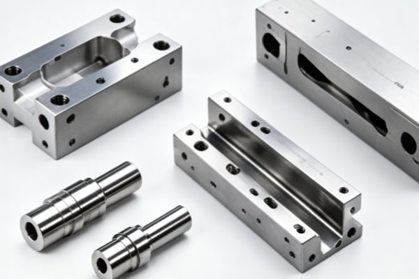
How Can Machining Accuracy Be Ensured for Automatic Loading and Unloading Equipment Parts?
Automatic loading and unloading mechanisms involve multiple continuous movements. Key dimensions are interconnected, so production requires a clear accuracy control process.
Check Drawings and Structures Before Machining
Before formal production, part designs should be reviewed from a manufacturing perspective to identify issues that may affect machining and assembly. When confirming critical tolerances, distinguish between general dimensions and important dimensions related to robotic arms, grippers, and positioning mechanisms. When checking thin walls and deep grooves, evaluate machining rigidity, tool access, and chip evacuation conditions. When determining machining datums, plan positioning surfaces and clamping methods according to assembly relationships. Thorough preliminary review can reduce frequent process modifications during machining.
Select CNC Machining Methods According to the Structure
Different parts have different requirements for the number of machining surfaces and tool angles. The machine type should be selected according to the geometric structure.
- 3-Axis CNC: Suitable for mounting plates, brackets, and conventional fixtures.
- 4-Axis CNC: Suitable for parts requiring machining from multiple directions.
- 5-Axis CNC: Suitable for complex curved surfaces, multi-sided structures, and components where repeated setups need to be minimized.
- CNC Turning: Suitable for shafts, sleeves, and other rotational parts.
Matching the machining method to the part structure helps control machining efficiency and dimensional consistency.
Inspect Critical Dimensions After Machining
After manufacturing, targeted inspection should be carried out according to engineering drawings and assembly requirements.
- Hole Diameter and Hole Spacing: Confirm accurate mechanical connections and mounting positions.
- Flatness and Perpendicularity: Check whether mounting datums meet assembly requirements.
- Concentricity and Position Accuracy: Focus on the fit between rotating components and motion mechanisms.
- CMM Inspection: Suitable for parts with complex structures or high accuracy requirements.
Inspection results provide clear dimensional data for part assembly.
How Should Materials Be Selected for Automatic Loading and Unloading Equipment Parts?
Material selection determines part weight, strength, wear resistance, and machining performance. It should be based on movement speed, load, and operating environment.
Aluminum Alloys for Moving Structures
Components such as robotic arm connectors, fixture bases, and mounting plates usually need to control weight to reduce the load on motion mechanisms. 6061 aluminum alloy is suitable for brackets, base plates, and conventional connectors, while 7075 aluminum alloy is suitable for lightweight structures requiring higher strength. Aluminum alloy surface treatments can be selected according to wear resistance, corrosion protection, or appearance requirements. For high-speed motion mechanisms, reasonable control of part weight can help improve overall dynamic response.
Steel and Engineering Plastics for Specific Applications
Different functional areas have different material priorities, allowing load-bearing components and sliding components to use different material systems.
- Steel: Suitable for positioning and connecting components requiring high load capacity and wear resistance.
- Stainless Steel: Suitable for humid environments or areas exposed to corrosion risks.
- POM: Suitable for certain low-friction and wear-resistant guide structures.
- PEEK: Suitable for specialized components requiring higher temperature resistance and wear resistance.
Selecting materials according to operating conditions helps match part performance with the equipment’s working environment.
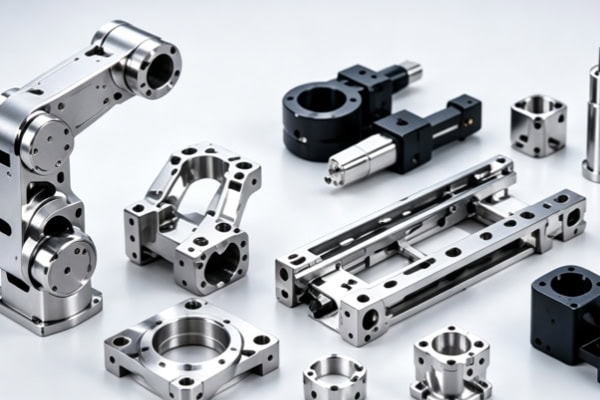
How Should You Choose a Machining Supplier for Automatic Loading and Unloading Equipment Parts?
Automation equipment projects usually involve design verification, prototype assembly, and batch manufacturing. The supplier’s ability to provide continuous support can affect project execution efficiency.
Evaluate Multi-Axis Machining and Precision Manufacturing Capabilities
When purchasing machining services, confirm whether the manufacturer has equipment and processes capable of covering different part structures.
- 3-Axis, 4-Axis, and 5-Axis Machining: Meet the manufacturing requirements of parts with different levels of structural complexity.
- Precision CNC Milling: Handles hole positions, slots, curved surfaces, and complex profiles.
- CNC Turning: Covers rotational components such as shafts and sleeves.
A reasonable range of machining capabilities can reduce the need to coordinate with multiple suppliers during a project.
Evaluate DFM, Inspection, and Batch Delivery Capabilities
In addition to machining equipment, engineering support and production management also affect project implementation.
- DFM Analysis: Identify potential manufacturing risks before production.
- Dimensional Inspection: Use measurement data to confirm that critical features meet drawing requirements.
- Prototype and Small-Batch Production: Facilitate assembly and functional verification by R&D teams.
- Transition to Mass Production: Allow validated part solutions to continue into subsequent orders.
Effective coordination between engineering and production can help shorten the transition from prototype validation to formal procurement.
The design of automatic loading and unloading equipment parts involves motion mechanisms, positioning systems, and load-bearing structures. Machining solutions need to be developed around specific drawings, tolerances, and operating conditions. TiRapid provides precision CNC milling, 5-axis machining, turning, and prototype-to-production services, supported by DFM analysis and quality inspection processes to provide automation equipment manufacturers with machining support from part development through production delivery.
















