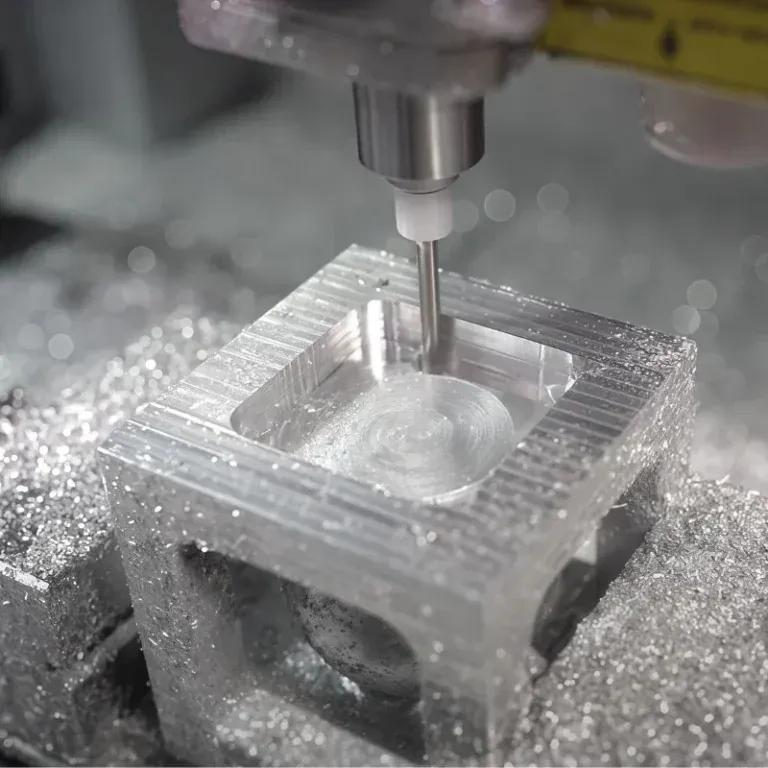
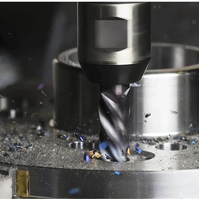
Automotive chassis systems perform important functions such as supporting the vehicle body, transmitting power, controlling steering, and maintaining driving stability. They contain a large number of metal parts with precise dimensions and complex structures. During assembly, chassis parts usually need to maintain proper fits with shafts, brackets, connectors, and other components. Therefore, hole positions, dimensions, flatness, concentricity, and surface quality can all affect the final assembly result. Common CNC-machined automotive chassis parts include suspension brackets, steering connectors, brake components, wheel hub-related parts, transmission connectors, mounting bases, and various customized structural components.
CNC machining can perform milling, turning, drilling, tapping, and precision finishing on aluminum alloys, steel, stainless steel, and other materials according to 3D models, 2D engineering drawings, or sample requirements. For automotive chassis parts that require rapid prototyping, small-batch validation, or continuous mass production, a suitable machining solution can reduce dimensional deviations and assembly problems while improving production efficiency. TiRapid can develop corresponding machining solutions based on part structure, material, quantity, and precision requirements, providing customized manufacturing services for precision automotive chassis parts from prototypes to mass production.
CNC Machining Requirements for Automotive Chassis Parts
Common Types of Chassis Parts
Automotive chassis systems contain many different parts, with significant differences in structure, dimensions, and operating conditions. Some parts are mainly used for mounting and connection and require multiple holes to maintain accurate positions. Some parts need to withstand continuous mechanical loads and therefore have higher requirements for material strength and machining accuracy. Other parts feature curved surfaces, grooves, stepped holes, and other complex structures that require multiple machining operations. CNC machining can be used to manufacture suspension mounting bases, steering components, brake mounting parts, control arm connectors, shock absorber brackets, transmission connectors, and other customized chassis structural parts. By controlling tool paths through CNC equipment, complex contours and precision holes can be machined with consistent results.
| Common Chassis Part Structures and CNC Machining | ||
| Suspension brackets | Hole positions, mounting surfaces, reinforcement structures | Milling, drilling, tapping |
| Steering connectors | Round holes, shaft holes, curved surfaces | Turning, milling, drilling |
| Brake mounting parts | Multiple holes, stepped surfaces | Milling, drilling, chamfering |
| Shock absorber brackets | Mounting holes, connection surfaces | Milling, drilling, tapping |
| Transmission connectors | Shaft holes, keyways, end faces | Turning, milling, precision finishing |
| Customized chassis structural parts | Irregular contours | Multi-axis CNC machining |
Dimensional and Assembly Requirements
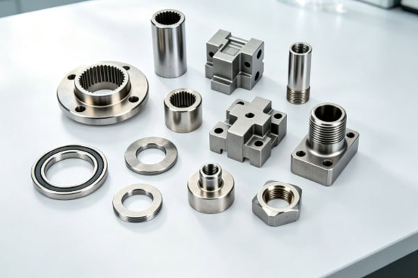
Automotive chassis parts are generally not used independently but need to be connected or assembled with other components. Therefore, accurate dimensions of an individual part do not necessarily mean that machining is complete. The distance between holes, hole diameters, mounting surface dimensions, and positional relationships between different features also need to be controlled. For shaft-related connection parts, the fit between the hole diameter and outer diameter must also be machined according to drawing requirements.
Processing of Complex Structures
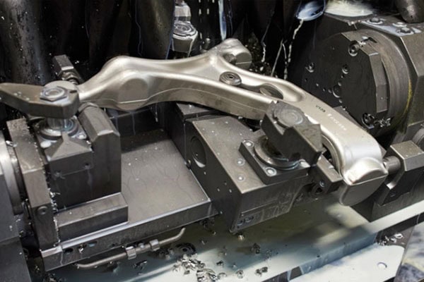
Chassis parts often include deep holes, inclined surfaces, curved surfaces, grooves, and mounting surfaces in multiple directions. The more complex the structure, the more important it is to arrange the machining sequence properly. Conventional three-axis CNC equipment can be used for standard flat surfaces, holes, and grooves. For parts with more complex structures or requiring machining in multiple directions, multi-axis machining can be selected according to actual requirements to reduce positional errors caused by repeated clamping. Before machining, checking the drawings and models can help identify issues such as excessively thin structures, deep cavities, and areas that cannot be reached by cutting tools. The machining method can then be adjusted accordingly to reduce rework during formal production.
CNC Machining Solution for Precision Automotive Chassis Parts
Material Selection
The material of a chassis part needs to be determined according to its application, structural strength, weight, and surface treatment requirements. Common materials include aluminum alloys, carbon steel, stainless steel, and other engineering metals. Aluminum alloys are relatively lightweight and have good machinability, making them suitable for certain lightweight brackets, mounting bases, and structural parts. Steel provides good strength and wear resistance and is commonly used for load-bearing connectors and support components. Stainless steel is suitable for parts requiring higher corrosion resistance.
| Common Material Characteristics and Applicable Parts | ||
| Aluminum alloy | Lightweight, easy to machine | Brackets, mounting bases, structural parts |
| Carbon steel | High strength | Connectors, load-bearing parts |
| Stainless steel | Good corrosion resistance | Connectors, mounting parts |
| Alloy steel | Good strength and wear resistance | Load-bearing parts, transmission components |
The actual material still needs to be determined according to the customer’s drawings, product requirements, and operating conditions. For projects with a specified material grade, machining can be performed directly using the designated material.
Machining Process Planning
The machining sequence for automotive chassis parts is generally developed according to their structure. For plate-type or block-type brackets, the reference surface can be machined first, followed by the main external profile and hole positions, and finally the mounting surfaces and holes with higher precision requirements. For shaft-type or rotational parts, CNC turning can be used to machine external diameters, internal holes, end faces, and grooves, followed by milling or drilling when required. For complex parts, the clamping method needs to be properly designed to reduce errors caused by part movement during machining. TiRapid can evaluate machining requirements based on CAD drawings, 3D models, or product specifications provided by customers and provide DFM recommendations according to the part structure. Confirming critical dimensions, materials, quantities, and surface treatment requirements before formal production can help reduce subsequent modifications.
Surface Treatment and Finished Part Requirements
After CNC machining, some chassis parts may require anodizing, sandblasting, polishing, coating, plating, or other surface treatments to improve appearance and corrosion resistance. For mounting components, special attention should be given to holes, threads, and mating surfaces to prevent dimensional changes after surface treatment from affecting assembly. For exposed structural parts, an appropriate surface treatment can be selected according to product appearance requirements. After completion, dimensional and visual inspections can be performed according to project requirements, with critical areas verified against the drawings. For parts requiring batch delivery, consistent production standards can also be maintained throughout machining to provide good dimensional consistency between different batches.
Quality Control for Automotive Chassis CNC Machining
Pre-Machining Inspection
Machining quality control begins before production. After receiving customer drawings, the dimensions, materials, quantities, critical tolerances, and surface treatment requirements of the parts need to be confirmed. For parts with special structures, it is also necessary to check whether the cutting tools can properly reach the machining areas. If certain areas of the drawing may create machining risks, DFM recommendations can be provided before production. For example, when hole spacing is too small, wall thickness is too thin, or certain deep grooves are difficult for cutting tools to machine, communication can take place in advance to reduce production issues.
In-Process Control
During machining, equipment parameters, tool conditions, and clamping methods can all affect final dimensions. A reasonable machining sequence can reduce part deformation and minimize positional deviations caused by repeated clamping. For holes, mounting surfaces, and mating areas with high precision requirements, precision finishing operations can be arranged. For complex parts, suitable equipment and machining methods can be selected according to the actual structure to maintain stable control of critical dimensions.
Finished Part Inspection
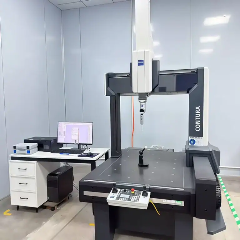
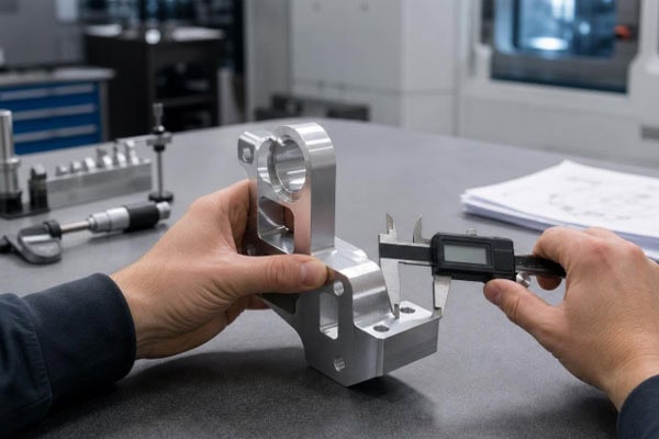
After machining is completed, parts need to undergo dimensional and visual inspections. Critical areas can be measured according to customer drawings, including external dimensions, hole diameters, hole spacing, thickness, and key mating dimensions.
| Inspection Item and Main Content | |
| Dimensional inspection | Length, width, thickness, diameter |
| Hole position inspection | Hole diameter, hole spacing, hole depth |
| Visual inspection | Burrs, scratches, machining marks |
| Thread inspection | Thread dimensions and integrity |
| Surface inspection | Surface treatment and appearance condition |
| Assembly dimensions | Whether critical connection positions meet drawing requirements |
Through pre-machining confirmation, in-process control, and finished part inspection, the process from drawings to finished parts can be made more consistent, supporting subsequent assembly and application.
TiRapid Customized Automotive Chassis Part Services
Prototype, Small-Batch, and Mass Production Support
Automotive chassis part development typically involves prototype production, dimensional validation, and formal production. Different stages have different requirements for quantities and delivery times, so machining services need to provide sufficient flexibility. TiRapid supports single-piece prototypes, small-batch production, and large-scale manufacturing, with production methods arranged according to the project stage. During new product development, prototypes can be produced first for structural and assembly validation. After the design is confirmed, the project can proceed to mass production, reducing the pressure of making a large initial investment.
Machining Support from Drawings to Finished Parts
Customers can provide 2D engineering drawings, 3D models, or relevant part information. TiRapid evaluates machining requirements based on product structure, material, and quantity and provides DFM reports and quotation support. TiRapid provides precision CNC machining, sheet metal fabrication, 3D printing, and other manufacturing services and can select appropriate machining methods according to different part requirements. For projects requiring the combined manufacturing of multiple parts, this can also reduce the time customers spend searching for separate suppliers.
Why Choose TiRapid
TiRapid follows ISO9001 certification standards and provides free DFM reports, instant quotations, and dedicated support. After customers submit part drawings, they can receive evaluations covering machining feasibility, materials, and production methods. TiRapid supports responses within 3 minutes and provides free quotations within 4 hours. Whether it is a single automotive chassis prototype or continuously produced small-batch or mass-production parts, a machining solution can be developed according to actual requirements.
Features of TiRapid Automotive Chassis Precision Part Machining Services:
- Supports precision CNC machining, sheet metal fabrication, and 3D printing
- Supports single-piece prototypes, small-batch production, and large-scale manufacturing
- Provides free DFM reports and machining feasibility evaluations
- Implements quality management according to ISO9001 certification standards
Frequently Asked Questions
Q1: What information is required for a quotation for automotive chassis parts?
A 3D model, 2D drawing, material, quantity, and surface treatment requirements are generally sufficient. If a complete drawing is not yet available, existing product information can also be provided for the engineering team to further confirm machining requirements.
Q2: Can complex automotive chassis brackets be machined?
Yes. Parts with multiple holes, curved surfaces, grooves, or mounting surfaces in different directions can be machined using suitable CNC machining methods according to their structure. Machining feasibility will be checked before formal production.
Q3: Can aluminum alloy and steel chassis parts be machined?
Yes. Common metal materials such as aluminum alloys, steel, and stainless steel can be CNC machined according to part requirements. The specific material is determined based on customer drawings and product requirements.
TiRapid provides precision CNC machining, sheet metal fabrication, 3D printing, and other services, supporting single-piece prototypes, small-batch production, and large-scale manufacturing. For automotive chassis brackets, connectors, mounting bases, steering and transmission-related parts, TiRapid can develop machining solutions according to drawings and actual requirements. We follow ISO9001 certification standards and provide free DFM reports, instant quotations, and dedicated support. After drawings are submitted, TiRapid responds within 3 minutes and provides a free quotation within 4 hours. If you are looking for a CNC machining supplier for precision automotive chassis parts, you can send your part drawings, 3D models, materials, and quantities to TiRapid. The engineering team will evaluate the machining method, production requirements, and quotation according to the actual part structure, providing complete support from prototypes to mass production.
Email: projects@tirapid.com
Phone: +86 760 8999 8536