Communication modules are essential components for data transmission in robotic control systems, industrial automation equipment, and intelligent terminals. They typically integrate communication chips, PCB assemblies, interface components, antenna connectors, and thermal management elements. During long-term operation, communication modules may be exposed to vibration, dust, temperature fluctuations, electromagnetic interference, and frequent connector insertion and removal. As a result, the enclosure must provide more than basic protection. It also needs to offer stable mounting structures, effective heat dissipation, accurate interface positioning, and reliable mechanical support. CNC precision machining enables communication module enclosures to be manufactured from aluminum alloys, stainless steel, copper alloys, and engineering plastics through milling, drilling, tapping, chamfering, and precision cavity machining. This allows manufacturers to maintain tight dimensional tolerances, accurate hole positions, controlled flatness, and consistent assembly interfaces. For robotic applications, customized CNC machining provides flexible enclosure dimensions and structures for controllers, robotic arms, end-of-arm equipment, mobile platforms, and industrial communication systems. It also supports prototype development, small-batch production, and volume manufacturing, providing a reliable mechanical housing for advanced communication modules.
CNC Machining Processes and Manufacturing Advantages for Communication Module Enclosures
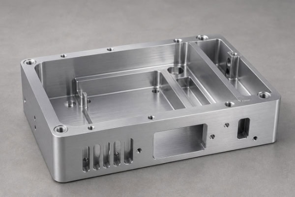
Communication module enclosures often feature thin walls, internal cavities, mounting holes, connector openings, positioning grooves, and heat dissipation structures. The machining process must maintain both external dimensions and internal structural accuracy. A well-planned CNC process can reduce positioning errors caused by repeated clamping while maintaining consistent relationships between mounting surfaces and interface openings. For robotic communication equipment, material selection and wall thickness must also be matched to the operating environment so that the enclosure achieves a balance between low weight and sufficient structural strength.
Precision CNC Machining Process for Communication Module Enclosures
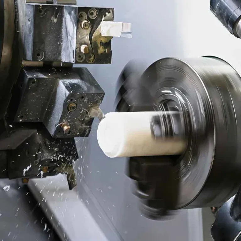
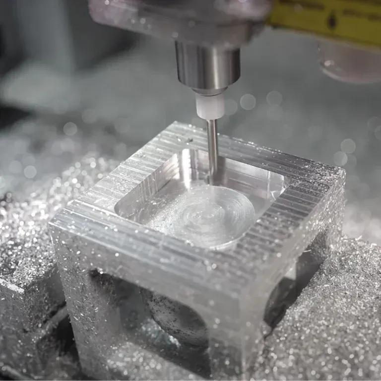
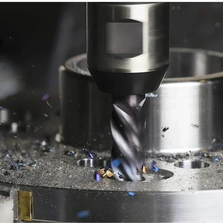
CNC machining of a communication module enclosure generally begins with a 3D CAD model and engineering drawings. The manufacturing team determines the raw material dimensions, machining datums, clamping method, and machining sequence according to the enclosure design. Aluminum alloy housings are commonly produced through high-speed milling for external contours, mounting surfaces, and internal cavities, followed by drilling and tapping for mounting screws, positioning holes, and communication interfaces. For compact communication modules with dense hole patterns, high-speed spindles and small-diameter cutting tools can be used to achieve accurate feature machining.
When machining internal cavities, tool overhang and cutting load must be carefully controlled to prevent thin walls from deforming. For PCB installation, internal support pillars, positioning grooves, and stepped surfaces can be incorporated into the enclosure. Precision machining ensures that the PCB remains properly supported after installation. Connector openings, Ethernet ports, aviation connectors, cable outlets, and other interfaces also require accurate positional relationships to simplify assembly.
CNC machining can further produce chamfers, countersunk holes, threaded holes, sealing grooves, and other detailed features. These features improve assembly quality and reduce interference between components. For complex curved surfaces or multi-directional interfaces, four-axis or five-axis CNC machining can reduce the number of setups and improve dimensional consistency.
CNC Machining Production Workflow for Communication Module Enclosures
Communication module enclosures are precision structural components, so the manufacturing workflow needs to balance production efficiency, dimensional stability, and assembly requirements. Communication modules installed on robots may experience continuous vibration during operation. If mounting holes, positioning structures, or connector interfaces have excessive dimensional deviations, electrical connections and equipment maintenance may be affected.
A typical CNC machining workflow includes the following steps:
- Drawing and 3D model verification: Confirm enclosure dimensions, wall thickness, hole locations, thread specifications, assembly datums, and surface treatment requirements.
- Material and blank preparation: Select aluminum alloy, stainless steel, copper alloy, or engineering plastic according to strength, weight, thermal conductivity, and environmental requirements.
- Datum surface machining: Create stable reference surfaces for subsequent cavity, hole, and mounting surface machining.
- External and cavity machining: Use CNC milling to produce external contours, internal cavities, steps, grooves, and support structures.
- Hole and thread machining: Produce mounting holes, positioning holes, connector openings, and threaded holes while maintaining accurate diameters and locations.
- Finishing and chamfering: Finish critical surfaces and mating areas while removing burrs and minimizing assembly interference.
- Surface treatment: Apply anodizing, sandblasting, coating, plating, passivation, or other treatments according to the application.
- Final inspection and packaging: Inspect critical dimensions, threads, appearance, flatness, and hole positions before protective packaging.
A standardized manufacturing workflow helps transform the raw material into a communication module enclosure that meets precise assembly requirements. Stable process control also helps reduce dimensional variation between production batches.
Common Materials and Performance of Communication Module Enclosures
Different robotic communication systems have different requirements for weight, thermal performance, corrosion resistance, and mechanical strength. Material selection should be based on the operating environment and enclosure structure.
| Material | Typical Performance | Suitable Applications |
| 6061-T6 Aluminum Alloy | Lightweight, machinable, good thermal performance | Robot communication modules, industrial communication boxes |
| 7075-T6 Aluminum Alloy | High strength with low weight | High-load mobile robot communication components |
| 304 Stainless Steel | Corrosion resistance and high structural strength | Communication equipment for harsh environments |
| Copper Alloys | Excellent thermal and electrical conductivity | Heat dissipation and electromagnetic shielding structures |
| PEEK | High-temperature resistance, electrical insulation, chemical resistance | Specialized industrial communication modules |
| 5052 Aluminum Alloy | Good corrosion resistance and forming performance | Lightweight communication equipment enclosures |
6061-T6 aluminum alloy provides a strong overall balance for communication modules installed on mobile robots and robotic arms. When higher mechanical strength is required, 7075-T6 can be considered. Stainless steel and engineering plastics can be selected for applications involving corrosive environments, high temperatures, electrical insulation, or specialized chemical conditions.
Applications, Usage Methods, Functions, and Performance Requirements of Robotic Communication Module Enclosures
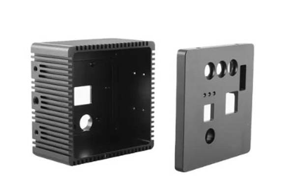
The function of a communication module enclosure extends beyond protecting internal electronic components. When installed on robotic equipment, the enclosure may also support PCB mounting, interface protection, heat transfer, equipment attachment, and maintenance operations. Robotic arms, AGVs, AMRs, machine vision systems, industrial gateways, and automated production lines operate under different conditions, making customized enclosure structures highly valuable. Proper positioning of interfaces, mounting holes, and internal supports allows the communication module to integrate efficiently into the robot body or control system.
Typical Applications of Robotic Communication Module Enclosures
Communication module enclosures can be used in industrial Ethernet systems, wireless communication equipment, fieldbus networks, machine-to-machine communication systems, and industrial data acquisition platforms. Different applications have different structural requirements. Robotic arms often prioritize low weight and vibration resistance, while industrial communication gateways may place greater emphasis on heat dissipation, dust protection, and interface durability.
Typical applications include:
- Industrial robots: Used for robotic controllers, joint communication units, and internal data transmission systems, providing secure mounting and protection for communication electronics.
- Collaborative robots: Compact aluminum CNC enclosures can reduce weight and space requirements while maintaining reliable connector positioning.
- AGVs and AMRs: Mobile robots require enclosures with good vibration resistance and sufficient space for wireless communication components and control boards.
- Machine vision equipment: Precision openings and mounting holes can accommodate industrial cameras, vision controllers, connectors, and mounting brackets.
- Automated production lines: Industrial gateways, PLC communication modules, and data acquisition units require long-term structural stability, heat dissipation, and convenient maintenance.
- Intelligent inspection equipment: Portable inspection robots and automated inspection platforms can use lightweight customized enclosures designed according to their specific dimensions.
These applications place high demands on dimensional consistency and interface positioning. Customized CNC machining allows the enclosure geometry to be adapted to the available installation space and system architecture.
Usage Methods and Structural Functions of Communication Module Enclosures
Before installation, the positions of the internal PCB, power connectors, communication interfaces, and mounting screws should be verified. During assembly, the PCB or communication components are normally secured to internal support pillars and positioning grooves. External cables are then connected, followed by fastening the upper and lower enclosure sections or securing the enclosure to an equipment mounting bracket.
For modules with high thermal loads, the enclosure can be designed with direct contact areas for chips, heat sinks, or thermal interface components. This allows heat generated during operation to transfer more efficiently toward the external enclosure surface.
The enclosure may also incorporate sealing grooves, dust-resistant structures, shielding contact areas, and cable management features. For robotic equipment requiring frequent maintenance, an optimized screw layout can shorten disassembly time. For permanently mounted communication modules, positioning pins and reinforcing ribs can improve structural stability.
Functional and Performance Requirements for Communication Module Enclosures
Communication module enclosures need to balance mechanical protection, heat dissipation, interface support, and electromagnetic compatibility. Robots operating at high speed or under continuous duty may generate vibration and mechanical shock, so the enclosure must maintain structural integrity without excessive deformation that could affect the PCB or connectors.
| Function / Performance | Requirement | CNC Structural Design |
| Internal Protection | Reduce dust, impact, and mechanical damage | Controlled wall thickness and enclosed cavities |
| Heat Dissipation | Transfer internal heat to the outside | Machined heat dissipation surfaces, grooves, or thermal contact areas |
| PCB Mounting | Prevent circuit board movement | Support pillars, positioning holes, and mounting steps |
| Interface Protection | Maintain stable connector positioning | Precision connector openings and mounting holes |
| Vibration Resistance | Withstand robotic movement | Optimized wall thickness, reinforcing ribs, and mounting structures |
| EMC Performance | Reduce electromagnetic interference | Shielding contact areas and conductive connection structures |
| Maintenance Convenience | Simplify module removal and replacement | Optimized screw layout and assembly interfaces |
| Dimensional Consistency | Meet repeated assembly requirements | Consistent datums and stable CNC processes |
These structural characteristics directly influence the operating stability of communication modules. Through precision CNC machining and optimized enclosure design, the housing can support installation, protection, thermal management, and long-term operation in robotic systems.
Customized CNC Machining and Quality Control for Communication Module Enclosures
Robotic equipment comes in many configurations, and communication modules can differ significantly in dimensions, connector locations, mounting positions, and internal layouts. A standard enclosure may not always fit the available installation space. CNC customization allows manufacturers to develop machining solutions based on customer 3D models, engineering drawings, or physical samples. Material selection, wall thickness, hole locations, surface treatment, and production volume can all be incorporated into the manufacturing process. Small-batch prototypes can be produced for initial assembly testing, while the structure can then be optimized according to actual installation feedback before moving into stable volume production. This approach is particularly suitable for robotic communication modules progressing from research and development to commercial production.
Methods for Improving CNC Machining Accuracy of Communication Module Enclosures
Communication module enclosures often contain numerous mounting holes and interface openings. Even a small local deviation can affect the final assembly position. Machining accuracy should be controlled through equipment selection, tooling, fixturing, and process parameter management.
- Use consistent machining datums: Keep critical mounting surfaces, interface surfaces, and positioning structures referenced to stable datums whenever possible.
- Optimize clamping methods: Use uniform clamping for thin-wall aluminum enclosures to reduce deformation and post-machining springback.
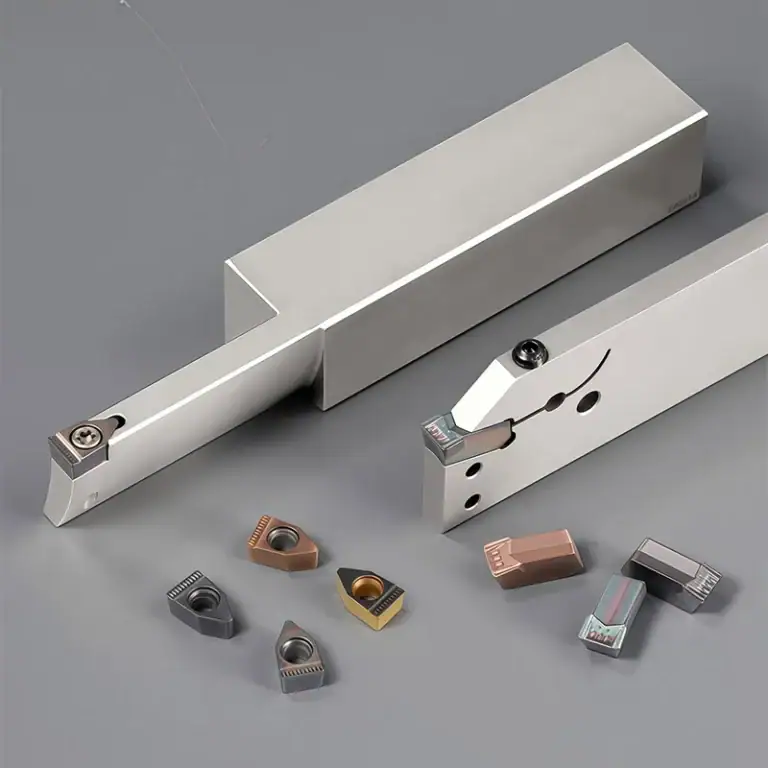
- Select suitable cutting tools: Choose milling cutters, drills, and taps according to material hardness, cavity depth, and feature geometry.
- Control cutting parameters: Match spindle speed, feed rate, and cutting depth to reduce vibration and excessive cutting forces.
- Separate roughing and finishing: Remove most of the material during rough machining before precision finishing of critical surfaces, holes, and mating areas.
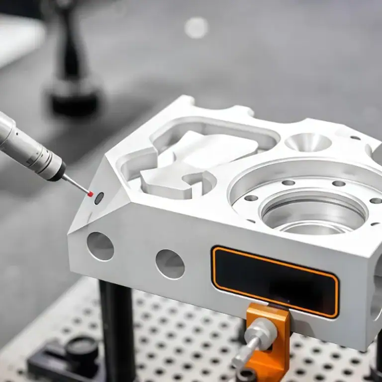
- Strengthen in-process measurement: Use calipers, micrometers, height gauges, optical measurement systems, or CMM equipment to verify critical dimensions.
- Control tool wear: Establish tool-life management to prevent gradual changes in hole diameter, surface quality, and dimensional accuracy.
- Perform assembly verification: Test prototypes with PCBs, connectors, brackets, and fastenersto identify potential assembly issues.
These process controls can improve dimensional stability and batch-to-batch consistency. For precision robotic communication components, process inspection and final assembly verification are both important quality control measures.
Surface Treatment and Maintenance of Communication Module Enclosures
After CNC machining, communication module enclosures often require surface treatment to improve appearance, corrosion resistance, wear resistance, or electrical performance. Common treatments for aluminum housings include anodizing, sandblasted anodizing, and coating, while stainless steel housings may use passivation, brushing, or other finishing processes.
When the enclosure is designed for electromagnetic shielding, conductive contact areas should be defined before surface treatment. This prevents insulating coatings from interfering with electrical continuity between shielding surfaces.
During operation, connectors should be protected against lateral impact, and mounting screws, brackets, and cable outlets should be checked periodically for looseness. For housings with heat dissipation grooves, the thermal areas should be kept clean to prevent excessive dust accumulation from reducing heat transfer efficiency. Proper installation and maintenance can extend the service life and operational stability of both the enclosure and internal communication components.
Quality Inspection and Customized Supply Services for Communication Module Enclosures
Quality inspection for communication module enclosures can be established according to critical dimensions specified in engineering drawings. Inspection items may include external dimensions, internal cavity dimensions, hole diameters, hole spacing, threads, flatness, perpendicularity, and connector locations. Standard dimensions can be checked using calipers, micrometers, pin gauges, and other measuring tools, while complex positional relationships can be verified with optical measurement equipment or coordinate measuring machines.
For customized robotic industry orders, manufacturers may also need to manage material certificates, surface treatment specifications, batch identification, and packaging requirements. Prototype orders typically emphasize first-piece dimensional verification and assembly testing, while volume production requires stable process parameters and systematic inspection procedures.
Continuous management from drawing review, CNC programming, first-piece production, dimensional inspection, surface treatment, and final packaging helps ensure that communication module enclosures meet the requirements of robotic controllers, mobile robots, industrial gateways, and automated communication equipment. A reliable CNC machining supplier can also adjust production processes according to enclosure geometry, material requirements, tolerance specifications, and order volume, providing a flexible manufacturing solution for different stages of robotic communication equipment development.