Automatic feeding equipment handles workpiece transfer, positioning, and continuous material feeding. The manufacturing quality of its components affects feeding accuracy, operational smoothness, and equipment maintenance frequency. Guide components, transmission connectors, mounting brackets, and protective housings have different structures and operating conditions, so their quality cannot be judged by external dimensions alone. For equipment manufacturers and procurement teams, an effective manufacturing plan should define critical dimensions, fit requirements, surface conditions, necessary heat treatment and surface finishing, and acceptance criteria based on actual operating conditions. This helps reduce assembly adjustments, feeding jams, and premature component wear.
Manufacturing Requirements for Automatic Feeding Equipment Parts
Different components serve different functions, so their design and manufacturing requirements should be determined according to loads, movement patterns, and assembly relationships.
Dimensional Accuracy and Geometric Tolerances
Meeting the dimensional requirements on a drawing does not necessarily guarantee smooth equipment operation after assembly. The positional relationships between critical surfaces must also be considered.
- Mounting Brackets: Check mounting hole positions, datum surfaces, and the specified parallelism or perpendicularity of related surfaces to reduce assembly misalignment.
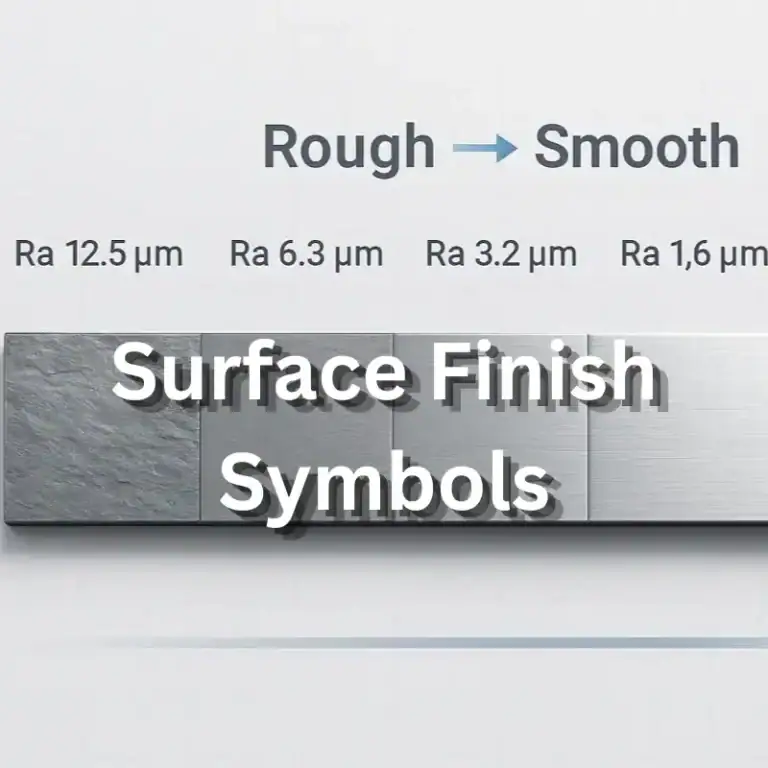
- Feeding Guide Components: Define the required flatness, parallelism, and surface roughness of working surfaces according to the guide structure to reduce feeding deviations and workpiece scratches.
- Transmission Connectors: For structures involving shaft-hole fits or rotary transmission, specify the required concentricity, position tolerances, and fit dimensions to prevent assembly interference.
Clearly defining critical dimensions and geometric tolerances in drawings and inspection requirements helps control assembly accuracy more effectively.
Material Selection and Operational Stability
Material selection should consider not only machining difficulty and purchasing costs but also contact wear, loading conditions, and equipment operation.
- Metal Components: Select suitable materials according to loads, structural rigidity, and the operating environment to prevent noticeable deformation of brackets or connectors.
- Contact and Guide Components: Match materials according to workpiece material, movement speed, and contact conditions to reduce excessive friction, wear, and surface damage.
- Dynamic Load-Bearing Structures: For mechanisms involving high-speed feeding, frequent starts and stops, or vibration, evaluate support rigidity, connection stability, and structural deformation to minimize feeding position fluctuations.
Materials and structures must work together to meet actual operating requirements rather than being selected solely according to the machining cost of individual parts.

CNC Machining Solutions for Automatic Feeding Equipment Parts
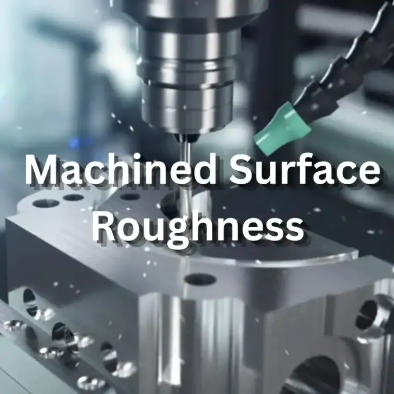
CNC machining can be used to manufacture components with mounting holes, datum surfaces, complex contours, and mating structures. Before machining, the process sequence should be determined according to the drawings, tolerance requirements, and subsequent operations.
Optimizing Machining Sequences and Clamping Methods
Proper datum selection and clamping sequence planning help control dimensional errors and geometric deviations. Components with multiple machined faces should use consistent positioning datums where practical to reduce errors caused by repeated clamping. Thin-walled parts or structures with limited rigidity require suitable support and clamping methods, along with an appropriate machining sequence to minimize deformation. Critical features such as transmission holes, guide surfaces, and mounting datums should be machined and inspected according to their tolerance requirements. Prototype assembly can be used to verify the results when necessary. A process plan tailored to critical structures helps reduce rework and improve consistency in batch production.
Heat Treatment, Surface Finishing, and Post-Processing
Heat treatment and surface finishing should be selected according to material properties, contact wear, and operating conditions. Not every component requires the same process. For parts exposed to high stress or requiring wear resistance, suitable heat treatment may be evaluated, with attention to dimensional changes afterward. Metal components can receive appropriate surface treatments based on corrosion resistance, wear resistance, and appearance requirements, provided the process is compatible with the base material, operating environment, and fit requirements. For surfaces requiring controlled roughness or fit accuracy, dimensions and surface conditions should be inspected after treatment to ensure assembly compatibility. Defining post-processing requirements before machining and including them in final inspection helps ensure that components meet their intended application needs.
Quality Inspection of Automatic Feeding Equipment Parts
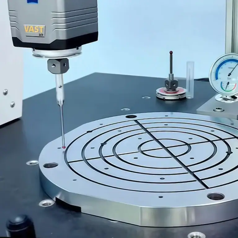
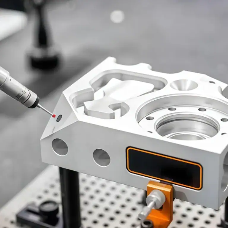
Quality acceptance should cover dimensions, geometric tolerances, surface conditions, and critical functional requirements. Appearance or a single dimensional measurement alone is not sufficient to determine whether a component is acceptable.
Inspection Priorities for Different Components
Inspection items should correspond to each component’s function and drawing requirements. The following table summarizes the main inspection priorities for common component types.
| Component Type | Main Inspection Items | Inspection Purpose |
| Mounting Brackets | Mounting hole positions, datum surfaces, relevant geometric tolerances | Ensure correct positioning and assembly |
| Feeding Guide Components | Working surface dimensions, parallelism, surface roughness, and appearance | Meet guiding and contact requirements |
| Transmission Connectors | Fit dimensions, concentricity or position tolerances, structural integrity | Reduce assembly interference and transmission deviations |
| Equipment Housings | Overall dimensions, connection holes, surface condition | Meet installation and protection requirements |
| Wear-Resistant Components | Critical dimensions, surface treatment condition, and hardness where required | Verify compliance with wear-related requirements |
Actual inspection items and tolerances should follow customer drawings and mutually agreed technical specifications rather than applying a single standard to every component.
Verifying Surface Quality and Batch Consistency
For feeding guide components and transmission parts, dimensional compliance should also be evaluated alongside surface conditions and assembly results.
- Surface Condition: Inspect critical contact surfaces for roughness, burrs, and visible defects according to drawing requirements to avoid affecting workpiece movement or component fit.
- Treatment Results: For components requiring heat treatment or surface finishing, verify the specified process requirements and recheck critical dimensions and mating features.
- Batch Inspection: Arrange first-article verification and in-process sampling according to order requirements. Investigate dimensional or surface abnormalities promptly when detected.
Combining process inspections with final acceptance helps reduce batch variations and improve delivery consistency.
How to Choose an Automatic Feeding Equipment Parts Manufacturing Supplier
A supplier’s drawing interpretation, process planning, and quality management capabilities affect component compatibility and project schedules. Procurement teams should evaluate the following factors before placing an order.
Evaluating Machining Capabilities and Technical Communication
A suitable supplier should understand each component’s assembly function and arrange machining and inspection according to drawing requirements.
- Drawing Evaluation: Confirm critical dimensions, geometric tolerances, fit relationships, and surface requirements while identifying machining challenges in advance.
- Process Coordination: For components requiring wear resistance, heat treatment, or surface finishing, confirm the process plan and how dimensions will be controlled after treatment.
- Prototype Verification: Check prototype dimensions and actual assembly performance before batch production, adjusting the machining plan when necessary.
Clarifying technical requirements before production helps reduce discrepancies between manufacturing results and equipment design expectations.
Confirming Lead Times, Costs, and Acceptance Responsibilities
Procurement quotations should reflect the actual manufacturing requirements of the components to avoid omitting necessary processes or inspections.
- Cost Evaluation: Clarify the costs associated with CNC machining, heat treatment, surface finishing, inspection, and packaging.
- Delivery Planning: Include machining, outsourced treatments, quality reinspection, and delivery schedules in the overall plan to reduce delays between processes.
- Acceptance Agreements: Confirm critical dimensions, surface conditions, required process records, and procedures for handling nonconformities in advance to minimize delivery disputes.
Transparent cost breakdowns and clearly defined acceptance responsibilities help procurement teams compare solutions and reduce coordination costs.
Manufacturing automatic feeding equipment parts requires consideration of machining accuracy, geometric tolerances, surface conditions, and actual operating conditions. Guide components must meet contact and sliding requirements, transmission connectors need controlled mating relationships, and load-bearing structures must provide adequate rigidity and stability. Heat treatment and surface finishing should be selected according to material properties and operating conditions, with manufacturing results verified through prototype evaluation and batch inspection. TiRapid provides customized CNC machining services based on customer drawings, materials, and order requirements, supporting automatic feeding equipment manufacturers with precision component production and delivery.