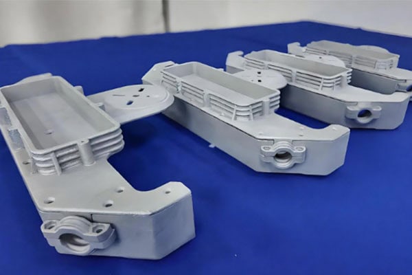
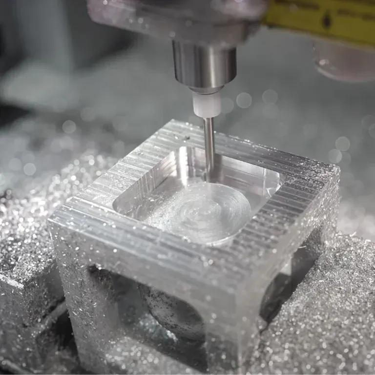
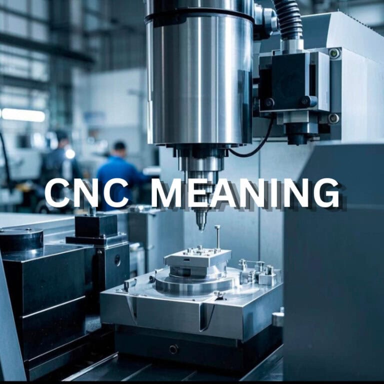
The aerospace industry has strict requirements for component accuracy, strength, weight, and reliability. Aircraft structural components, engine parts, aerospace brackets, satellite components, and other critical parts often feature complex surfaces, deep cavities, thin walls, irregular profiles, and multi-angle holes. These structures can be difficult to manufacture using conventional machining methods. As a result, aerospace complex parts machining increasingly relies on high-precision CNC equipment, 5-axis machining technology, and comprehensive quality control.
To meet the specialized manufacturing requirements of aerospace components, TiRapid can develop customized CNC machining solutions based on part drawings, materials, dimensions, tolerances, and application requirements. This provides aerospace manufacturers with flexible and reliable precision machining support for complex metal components.
Get 20% offf
Your First Order
Need custom metal and plastic parts?
What Are the Main Challenges of Aerospace Complex Parts Machining?
Aerospace components are rarely simple geometric parts. They may combine complex curved surfaces, angled surfaces, deep grooves, holes, and internal cavities. With conventional 3-axis CNC machining, multiple setups and repositioning may be required.
Repeated setups not only increase machining time but can also introduce cumulative positioning errors. For aerospace components with multiple machining surfaces, 5-axis CNC machining provides greater tool movement flexibility and can reduce the number of setups, making it well suited for complex geometries.
High-Strength Materials Can Be Difficult to Machine
Aerospace manufacturing frequently uses aluminum alloys, titanium alloys, stainless steel, and other high-performance metals. These materials provide excellent strength and durability, but some can be challenging to machine.
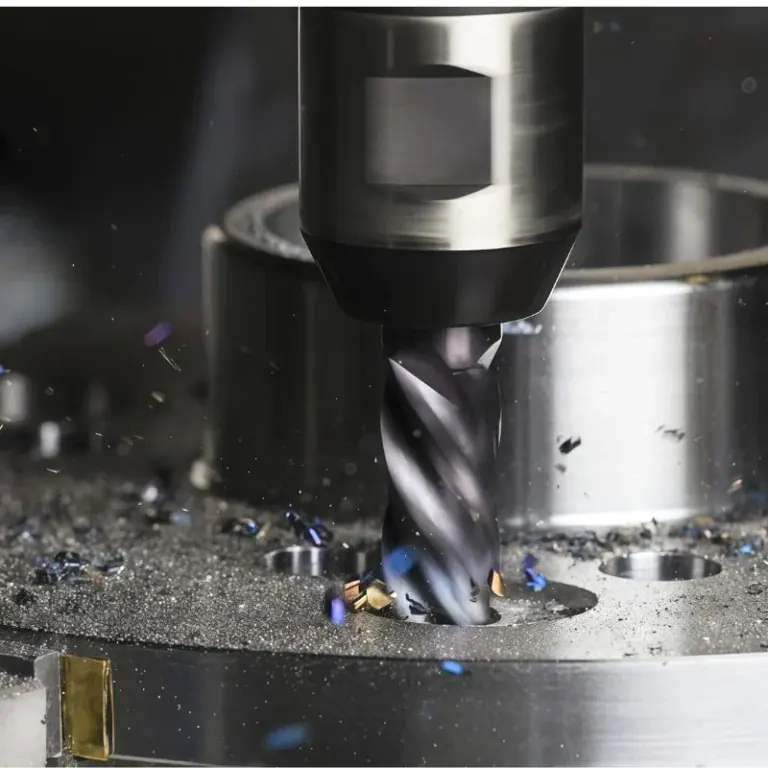
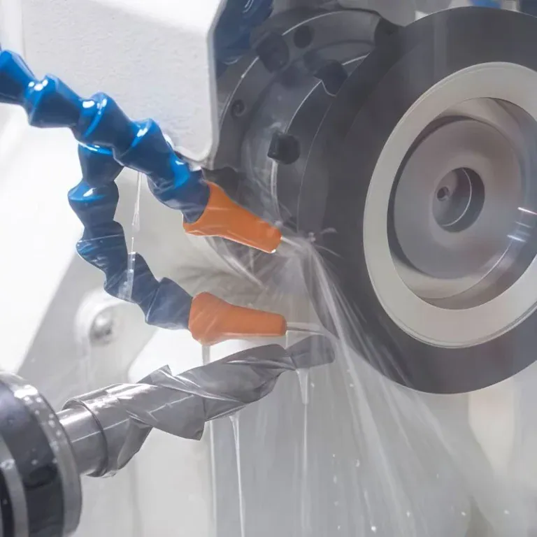
For example, titanium alloys can generate significant cutting heat during machining and may accelerate tool wear. Appropriate tool selection, cutting speed, feed rate, and cooling methods are therefore essential for maintaining machining stability and component quality.
Tight Dimensional Tolerances Are Required
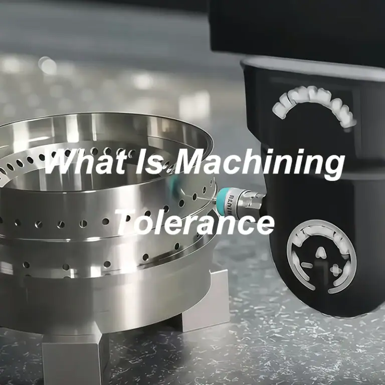
Aerospace components are often used in precision assemblies, making dimensional accuracy particularly important. Critical dimensions, hole diameters, positional accuracy, flatness, and profile tolerances must remain consistent.
During machining, material stress, cutting forces, and temperature variations can affect the final dimensions. Therefore, an effective manufacturing strategy should cover the entire process, from raw material preparation to final inspection.
Aerospace Complex Parts CNC Machining Solutions
Conduct DFM Analysis Based on Part Geometry
Before machining begins, the 3D model and engineering drawings should be carefully reviewed. Important factors include material, wall thickness, corner radii, hole locations, machining depth, and tolerance requirements.A comprehensive DFM analysis can identify potential manufacturing issues in advance and help determine the appropriate tooling, workholding method, and machining sequence, reducing the risk of rework.
Apply Multi-Axis CNC Machining Technology
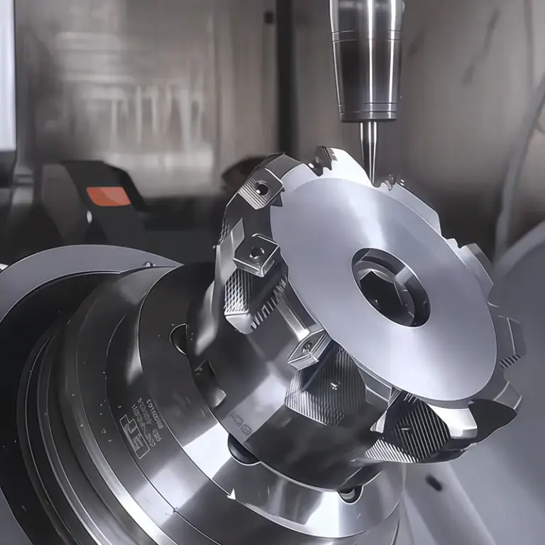
For complex curved surfaces, angled surfaces, and multi-directional structures, 5-axis CNC machining provides greater flexibility in tool movement. Compared with machining methods that require repeated repositioning, multi-axis machining can reduce setups and improve tool accessibility in complex areas.For aerospace engine components, complex brackets, curved housings, and other precision parts, 5-axis machining is particularly suitable for multi-angle and high-precision machining requirements.
Combine Roughing, Semi-Finishing, and Finishing
Complex aerospace components typically require multiple machining stages. Rough machining is used to remove large amounts of excess material efficiently. Semi-finishing establishes and stabilizes the component geometry, while finishing focuses on final dimensions, surface accuracy, and surface quality.A staged machining strategy can reduce stress changes caused by extensive material removal and help control deformation in complex components.
Common Aerospace Complex Parts and Machining Methods
Aerospace Component
Common Materials
Machining Challenges
Recommended Process
Aircraft Structural Parts
Aluminum Alloy, Titanium Alloy
Complex profiles, lightweight structures
3-Axis / 5-Axis CNC
Engine Components
Titanium Alloy, Stainless Steel
Heat, tool wear, complex surfaces
5-Axis CNC
Aerospace Brackets
Aluminum Alloy, Titanium Alloy
Multiple holes, tight tolerances
CNC Milling / 5-Axis CNC
Satellite Components
Aluminum Alloy, Titanium Alloy
Complex geometry, dimensional stability
Precision CNC
Aerospace Housings
Aluminum Alloy
Deep cavities, curved surfaces
CNC Milling
Precision Connectors
Aluminum, Stainless Steel
Small size, precision holes
Precision CNC Machining
How to Improve Aerospace Complex Parts Machining Accuracy?
Optimize Workholding
Complex aerospace components require appropriate fixtures and positioning methods based on their geometry. Stable workholding can reduce vibration during machining while preventing deformation caused by excessive or uneven clamping forces.For thin-wall, irregularly shaped, or low-rigidity aerospace components, auxiliary supports should also be positioned carefully to improve machining stability.
Select Appropriate Cutting Tools and Parameters
Tool type, tool diameter, feed rate, and cutting depth all affect machining performance. Different materials, including aluminum alloys, titanium alloys, and stainless steel, require suitable tooling and cutting parameters.For complex curved surfaces, toolpaths should also be optimized to maintain stable cutting conditions and reduce excessive cutting forces and vibration.
Perform Precision Inspection After Machining
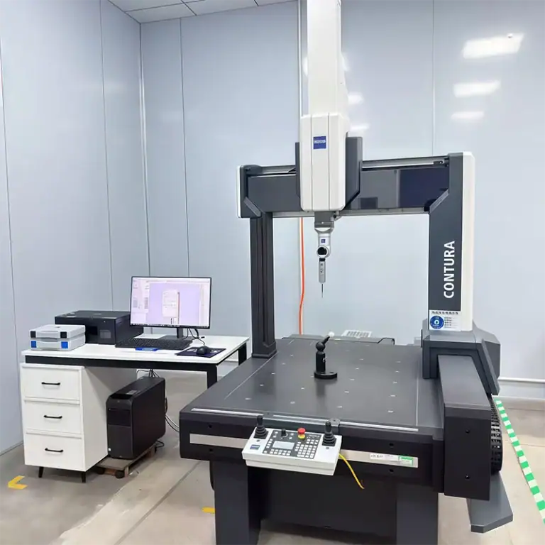
Aerospace complex components cannot rely solely on machining equipment to ensure quality. Final inspection is essential for confirming that critical dimensions meet engineering drawing requirements.Depending on the component, inspection may focus on hole diameter, positional accuracy, flatness, profile dimensions, and surface roughness. For high-precision components, a comprehensive inspection process helps maintain consistency across production batches.
TiRapid Aerospace Complex Parts Machining Advantages
TiRapid provides customized CNC machining services for complex precision components. Based on customer 3D models, 2D drawings, material specifications, and production volumes, TiRapid can develop suitable manufacturing strategies for different aerospace applications.With processes including CNC milling, CNC turning, and 5-axis CNC machining, TiRapid can accommodate a wide range of aerospace component geometries. For complex surfaces, multi-angle structures, and high-precision parts, multi-axis machining can reduce repeated setups while improving machining flexibility.By optimizing machining sequences, toolpaths, cutting parameters, and inspection procedures, manufacturers can achieve better control over dimensional accuracy, surface quality, and production consistency.
Aerospace complex parts machining requires a high level of expertise in equipment, process planning, and quality control. From DFM analysis and material selection to fixture design, CNC roughing, 5-axis precision machining, and final dimensional inspection, every stage can affect the quality of the finished component.For complex curved surfaces, multi-angle structures, high-strength materials, and tight tolerance requirements, a well-designed aerospace CNC machining solution can improve machining stability and production efficiency.TiRapid can provide customized precision machining support according to the geometry and application requirements of different aerospace components, delivering reliable manufacturing solutions for aircraft, engines, satellites, and other aerospace equipment.
Author
Galen Director and Founder
Committed to ensuring we provide the best possible service in the manufacturing industry.
CNC machining is used to manufacture precise metal and plastic components for automotive, medical, aerospace, industrial equipment, and electronic products. It transforms raw material into functional parts through computer-controlled milling,
A shaft must enter its mating bore, a bearing must stay seated, and a cover must locate correctly on its housing. Each function permits some dimensional variation. The engineering task
SFM machining uses surface feet per minute to measure the cutting speed between a rotating tool and the workpiece. It helps machinists calculate suitable spindle speeds, control cutting conditions, and
CNC is one of the core technologies behind modern manufacturing. It allows machines to follow programmed instructions and produce parts with controlled dimensions, repeatable movements, and less dependence on manual
A machined housing can have correctly sized holes and still fail to assemble if those holes are in the wrong locations. Checking each diameter tells you only part of the
Grinding is a precision machining process that removes material from a workpiece using a rotating abrasive wheel. Unlike conventional cutting tools, which remove material with defined cutting edges, grinding uses
A bracket may need a curved edge to clear an adjacent component. A housing may require an accurately shaped internal wall, while a mold needs a continuous surface that defines
The main spindle is one of the most important assemblies in a CNC machine. It provides the rotational motion required for cutting, holds either the cutting tool or the workpiece,
Guide pins are simple components, but they play a critical role in mold alignment, repeatable positioning, and long-term tooling stability. In injection molds, die sets, fixtures, and precision assemblies, a
CNC Part Manufacturing: Process, Quality & Design Guide CNC parts are used across aerospace, medical equipment, robotics, automotive systems, electronics, and industrial machinery because CNC machining can produce complex components
Two parts made from the same material can have very different milling prices. One may fit a standard vise and run with common tools. The other may need several setups,
Multiaxis machining is a CNC manufacturing process that allows the cutting tool, workpiece, or both to move across multiple controlled axes during machining. Instead of only cutting from one fixed