The wire EDM process is a precision machining method used to cut conductive materials with a thin electrically charged wire. Instead of using a rotating cutter, drill, or saw blade, it removes material through controlled electrical sparks. This makes it suitable for hard metals, narrow slots, complex profiles, and parts that require stable dimensional accuracy.
For manufacturers, wire EDM is valuable when conventional cutting tools are limited by tool radius, cutting force, tool wear, or material hardness. This article explains how the wire EDM process works, what steps are involved, which materials are suitable, and when this process should be used for precision machined parts.
What Is the Wire EDM Process?
The wire EDM process, also called wire electrical discharge machining or wire-cut EDM, is a non-contact machining method for conductive materials. A thin metal wire works as the electrode and follows a CNC-controlled path to cut profiles, slots, cutouts, and detailed metal features.
Unlike milling or turning, wire EDM does not remove material with a physical cutting edge. The wire does not press against the workpiece. Instead, controlled electrical discharges create heat in a small gap between the wire and the material, gradually eroding the required cutting path.
This process is commonly used for through-cuts, complex 2D profiles, small internal radii, narrow slots, and hardened metal parts. It is especially useful when the part geometry is difficult to machine with end mills, drills, saws, or other conventional cutting tools.
How the Wire EDM Process Works
The wire EDM process works by creating controlled electrical discharges between a thin wire electrode and a conductive workpiece. These sparks generate intense localized heat in a very small gap, melting and removing tiny particles of material along the programmed cutting path.
During machining, dielectric fluid flows through the cutting zone to cool the part, stabilize the discharge, and flush away eroded particles. This fluid is essential for maintaining cutting accuracy, preventing unstable sparks, and helping the wire produce a cleaner and more consistent edge.
The CNC system controls wire movement, cutting speed, wire tension, and offset compensation. Because the wire is continuously fed from a spool, fresh wire enters the cutting zone throughout machining, helping maintain stable cutting performance and repeatable dimensional accuracy.
Key Components in Wire EDM Machining
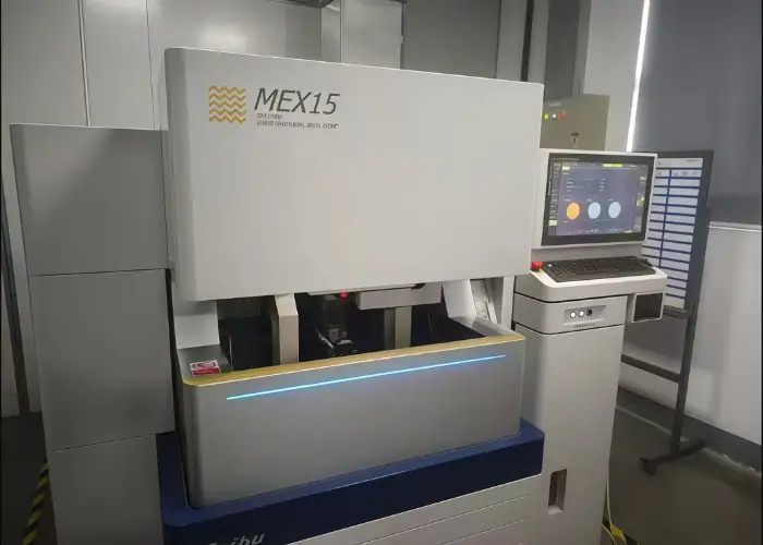
A wire EDM machine relies on several systems working together. The wire, power supply, guide system, tension control, dielectric fluid, and CNC control all affect cutting stability, accuracy, and surface quality. Understanding these components helps explain why setup and parameter control are so important.
EDM Wire
The EDM wire acts as the cutting electrode. Common wire materials include brass, zinc-coated brass, and other conductive wire types. Wire material and diameter affect cutting speed, kerf width, surface finish, and the smallest detail the machine can produce.
A thinner wire can create smaller internal radii and narrower slots, which is useful for fine features. However, thin wire may cut more slowly and can be less stable in thick materials. The wire size should match the part geometry and tolerance requirements.
Power Supply and Pulse Control
The power supply controls the electrical energy used to create sparks between the wire and the workpiece. Pulse control determines how long each discharge lasts and how often it occurs. These settings have a direct effect on cutting speed and surface quality.
Higher discharge energy can remove material faster, but it may create a rougher surface or increase the risk of unstable cutting. Lower energy settings may improve finish but reduce speed. The right balance depends on material, thickness, and tolerance.
Wire Guides and Tension System
Wire guides keep the wire positioned accurately as it moves through the cutting zone. The upper and lower guides support the wire path and help control straightness. Their condition and alignment can affect taper, profile accuracy, and repeatability.
The tension system keeps the wire straight during machining. If tension is too low, the wire may vibrate or bend, reducing cutting accuracy. If tension is too high, wire breakage may become more likely, especially during fine or complex cuts.
Dielectric Fluid and Flushing System
The flushing system delivers dielectric fluid to the cutting zone. Its job is to remove debris, cool the work area, and support stable electrical discharge. Poor flushing can cause unstable sparks, rough surfaces, inaccurate cuts, or wire breakage.
Flushing becomes more difficult in thick plates, narrow slots, and deep profiles. In these cases, debris may be harder to remove from the cutting gap. Stable fluid flow helps maintain clean cutting conditions and improves the consistency of the final edge.
Materials Suitable for the Wire EDM Process
Material selection is one of the first decisions in the wire EDM process. The workpiece must be conductive, but hardness is usually less of a problem than it is in conventional machining. This makes wire EDM useful for metals that are hard, heat treated, or difficult to cut mechanically.
Common Metals for Wire EDM
Wire EDM can machine many conductive metals, including tool steel, stainless steel, titanium, aluminum, copper, brass, carbide, and nickel alloys. These materials are common in aerospace, medical, automotive, tooling, electronics, and industrial equipment applications.
Tool steel and carbide are often used for dies, punches, molds, and wear-resistant tooling. Titanium and stainless steel are common for high-strength or corrosion-resistant parts. Copper and brass are often used for electrical and conductive components.
Why Hard Materials Are Suitable for Wire EDM
Hard materials are often difficult to mill because cutting tools can wear quickly, generate heat, or create vibration. Wire EDM avoids many of these problems because it does not rely on tool hardness or cutting edge pressure to remove material.
This makes wire EDM useful for hardened tool steel, carbide, and heat-treated parts. A component can be hardened first and then finished with wire EDM, helping maintain final geometry without the same tool wear problems found in conventional machining.
Materials That Cannot Be Cut by Wire EDM
The most important material limitation is electrical conductivity. Standard wire EDM cannot cut plastics, wood, glass, rubber, or most ceramics because these materials do not conduct electricity well enough for the discharge process.
This matters when choosing a manufacturing process. For plastic parts, CNC milling, routing, laser cutting, or waterjet cutting may be more suitable. Before choosing wire EDM, the material grade and cutting path should always be confirmed.
Advantages of Wire EDM for Precision Parts
Wire EDM is often selected when accuracy, fine detail, and low cutting force are more important than fast material removal. Its advantages are strongest in hard conductive materials, narrow profiles, tight internal features, and parts that must remain dimensionally stable.
High Accuracy for Complex Profiles
Wire EDM can produce accurate profiles, thin slots, small radii, and detailed cutouts. Because the wire follows a CNC-controlled path, the process can repeat complex shapes consistently. This is useful for parts that require precise mating surfaces or profile accuracy.
The process is especially helpful when standard cutting tools are limited by tool diameter. End mills cannot produce perfectly sharp internal corners, and very small tools may be fragile. Wire EDM can create tighter profiles with less tool access limitation.
Low Cutting Force and Less Distortion
One of the main benefits of wire EDM is low cutting force. Since the wire does not physically push against the workpiece, the part is less likely to bend, shift, or deform during machining. This is important for thin, delicate, or high-accuracy parts.
This advantage also supports post-heat-treatment machining. Parts that have already been hardened can still be cut accurately without applying heavy tool force. This helps manufacturers maintain dimensional stability in molds, dies, and precision metal parts.
Good Edge Quality and Reduced Burrs
Wire EDM often produces clean edges with little or no heavy burr formation. Since there is no cutting edge pushing through the material, the process can reduce the mechanical burrs commonly seen in sawing, milling, or drilling.
Edge quality depends on material, cutting parameters, wire size, and the number of finishing passes. If the part requires a better finish, additional skim cuts can improve smoothness, straightness, and dimensional control.
Limitations of the Wire EDM Process
Although wire EDM is precise, it is not suitable for every part. Its value depends on material conductivity, geometry, tolerance, production volume, and cost target. Understanding these limits helps engineers decide when wire EDM is the right process and when another method is more efficient.
Conductive Material Requirement
Wire EDM only works with conductive materials. This is the most important process boundary. If the workpiece cannot conduct electricity, the machine cannot create the controlled discharge needed to remove material.
This limitation means wire EDM is not suitable for most plastics, wood, glass, rubber, and non-conductive ceramics. For these materials, manufacturers usually choose CNC milling, laser cutting, waterjet cutting, or other suitable processes.
Slower Cutting Speed for Large Material Removal
Wire EDM is not usually the fastest method for removing large amounts of material. CNC milling, turning, or sawing can be much faster for roughing, pocketing, and general stock removal. Wire EDM is better for precision profiles than bulk material removal.
Cutting speed depends on material, thickness, wire size, flushing, tolerance, and surface finish requirements. Thick plates, tight tolerances, and multiple skim cuts can increase machining time, which can affect both cost and delivery schedule.
Geometry and Through-Cut Limitations
Wire EDM is mainly used for through-cut profiles because the wire must pass through the workpiece. It is excellent for slots, cutouts, external profiles, and internal shapes with starter holes, but it is not ideal for every 3D feature.
Blind pockets, complex 3D cavities, and enclosed shapes without wire access may require CNC milling or sinker EDM instead. This is why part geometry must be reviewed before choosing the process.
Cost Factors in Wire EDM Machining
Wire EDM cost is influenced by machine time, wire consumption, part thickness, material type, accuracy requirements, and the number of finishing passes. A simple profile may be affordable, while a thick, tight-tolerance part may take much longer.
The best way to control cost is to define functional requirements clearly. Not every edge needs the same tolerance or finish. Using wire EDM only for the features that need it can improve value without overprocessing the entire part.
Wire EDM vs CNC Milling
Wire EDM and CNC milling are not direct replacements. They solve different manufacturing problems and are often used together. Milling is usually better for fast material removal and 3D geometry, while wire EDM is better for fine profiles, hard conductive materials, and low-force cutting.
| Comparison Point | Wire EDM | CNC Milling |
| Cutting method | Uses electrical discharge between a thin wire and conductive workpiece | Uses rotating cutting tools to remove material mechanically |
| Suitable materials | Conductive metals such as steel, stainless steel, titanium, copper, carbide, and nickel alloys | Metals, plastics, and many machinable engineering materials |
| Best for | Narrow slots, small internal radii, through-cut profiles, hardened metals, and delicate parts | 3D surfaces, pockets, holes, contours, bulk material removal, and general part geometry |
| Cutting force | Very low cutting force because the wire does not physically push the workpiece | Higher cutting force because the tool directly contacts the material |
| Internal corner limits | Can create smaller internal radii depending on wire diameter | Limited by cutter diameter, especially for sharp internal corners |
| Speed | Slower for large material removal but precise for detailed cutting | Faster for roughing, stock removal, and many general machining tasks |
| Surface and edge quality | Can produce clean, low-burr edges, especially with skim cuts | Edge quality depends on tool sharpness, parameters, material, and finishing operations |
| Geometry limits | Mainly suitable for through-cuts and profiles that the wire can pass through | More flexible for 3D features, blind pockets, bosses, holes, and complex surfaces |
| Cost factors | Affected by wire use, machine time, skim cuts, material thickness, and tight tolerances | Affected by tooling, setup, machining time, tool wear, material, and feature complexity |
| Best manufacturing choice | When the part needs fine features, hard conductive materials, or low-distortion cutting | When the part needs fast machining, broad material options, or complex 3D geometry |
Common Applications of Wire EDM Machining
Wire EDM is used in industries where precision, repeatability, and material stability are important. It is especially useful for parts made from hard conductive materials or components that require fine profiles, tight slots, and stable dimensions.
Aerospace and Medical Components
Aerospace and medical parts often require tight tolerances, difficult materials, and reliable repeatability. Wire EDM can support these needs by cutting precise metal profiles with low mechanical stress and stable dimensional control.
In aerospace applications, it may be used for brackets, thin metal features, turbine-related components, and high-strength alloy parts. In medical manufacturing, it can be used for surgical tools, small stainless steel parts, and precision metal features.
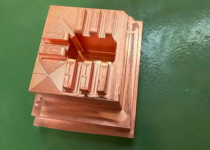
Mold, Die, and Tooling Parts
Wire EDM is widely used in mold, die, and tooling applications because these parts often require hard materials, sharp profiles, and high repeatability. Punches, dies, mold inserts, and carbide tooling components are common examples.
Tooling parts may need small internal corners, accurate slots, and precise mating features. Milling can be limited by tool radius or tool wear, especially after heat treatment. Wire EDM can cut these features with less mechanical stress.
Electronics and Semiconductor Equipment Parts
Electronics and semiconductor equipment often use small precision metal parts, conductive components, fixtures, and profiles. Wire EDM can support these applications when parts require clean slots, accurate cutouts, and stable dimensions.
In electronics, wire EDM may be used for contacts, connectors, shielding components, or small metal profiles. In semiconductor equipment, it is useful when fixtures, brackets, or conductive parts need fine slots and stable edge quality.
Automotive and Industrial Equipment Parts
Automotive and industrial equipment parts often include gears, wear components, tooling, fixtures, and high-strength metal profiles. Wire EDM can be useful when these parts require accuracy, hard materials, or difficult internal features.
In automotive applications, the process may support transmission-related parts, tooling components, prototype features, and precision metal profiles. For industrial equipment, it can help produce custom wear parts, jigs, fixtures, and machine components.
Design Tips for Wire EDM Parts
Good wire EDM design starts with confirming material conductivity, feature geometry, and tolerance requirements. The process is most useful for conductive materials, narrow slots, small internal radii, and through-cut profiles. If a simple feature can be milled faster, it may not need wire EDM.
Wire diameter should be considered early because it affects kerf width, slot size, and the minimum internal radius. Designers should also plan starter holes for closed internal profiles and avoid placing them on sealing surfaces, visible areas, or functional edges.
Tolerance and surface finish requirements should be applied only where they affect function. Over-specifying every edge can increase machining time, inspection cost, and lead time. Clear drawings help manufacturers choose the right process and control cost.
When to Choose the Wire EDM Process
Wire EDM should be selected based on real manufacturing needs, not only because it is precise. The best applications usually involve conductive materials, hard metals, narrow features, or part geometry that creates problems for conventional cutting tools.
Choose Wire EDM for Hard Conductive Materials
Wire EDM is a strong choice for hard conductive materials such as hardened tool steel, carbide, titanium, stainless steel, and nickel alloys. These materials can be difficult to machine with conventional cutting tools, especially when tight accuracy is required.
The process is especially useful after heat treatment. Instead of machining all features before hardening and risking movement, manufacturers can use wire EDM to finish key profiles after the material reaches its final hardness.
Choose Wire EDM for Narrow Slots and Small Internal Radii
Wire EDM is suitable when the design includes narrow slots, small internal radii, and detailed through-cut profiles. These features can be difficult for milling tools because cutter diameter limits the smallest radius and slot width.
A thin wire can create smaller features than many rotating tools. However, the wire still has a physical diameter, so internal corners cannot be perfectly sharp. Designers should confirm the minimum radius and slot width before finalizing drawings.
Choose Wire EDM When Part Distortion Must Be Reduced
Wire EDM is helpful when the part is thin, delicate, or sensitive to cutting force. Since the wire removes material through electrical discharge instead of direct pressure, it can reduce the risk of bending, vibration, and deformation.
Low cutting force does not remove the need for good fixturing and process control. The part still needs proper support, flushing, and inspection, but wire EDM can offer a safer option for sensitive precision geometry.
FAQs
Can wire EDM be used after heat treatment?
Yes. Wire EDM is often suitable for hardened parts because it removes material by electrical discharge instead of mechanical cutting pressure. This helps maintain accuracy after heat treatment, especially for tool steel, carbide, molds, dies, and precision metal components.
How does wire diameter affect the final part design?
Wire diameter affects the minimum internal radius, slot width, kerf size, and level of detail. A thinner wire can create smaller features, but it may reduce cutting speed and require more stable control. Designers should consider wire size before finalizing critical profiles.
Is wire EDM suitable for prototype and low-volume production?
Yes. Wire EDM can be suitable for prototypes and low-volume parts when the design includes tight tolerances, hard materials, or difficult profiles. For simple shapes or large material removal, CNC milling may be more cost-effective and faster.
What information should be included in a wire EDM RFQ?
A clear RFQ should include 2D drawings, 3D files if available, material grade, thickness, tolerance, quantity, surface finish, and critical features. This helps the manufacturer decide whether wire EDM, CNC milling, or a combined process is the best option.
Conclusion
The wire EDM process is best suited for conductive materials, complex profiles, narrow slots, small internal radii, and hardened precision parts. It offers high accuracy with little cutting force, making it useful when conventional machining may cause distortion, tool access limits, or burr issues. The right choice depends on material, geometry, tolerance, surface finish, production volume, and real functional requirements.
At TiRapid, we provide precision CNC machining services for custom metal and plastic parts, helping customers control machining quality, dimensional accuracy, and functional performance for demanding engineering applications.