
When many customers choose CNC milling, their biggest concern is often not whether the machine can run, but whether the parts will be stable after production, whether rework will be needed, and whether the overall delivery schedule will be affected. In real projects, issues such as dimensional deviation, surface burrs, tool wear, and unstable clamping are very common. Once the initial judgment is inaccurate, it can easily lead to higher costs, delayed delivery, and batch production risks. To make CNC milling more reliable, the key is not just to look at machine specifications, but to identify problems in advance, find the root causes, and optimize processes, tooling, and management together so that risks are controlled from the beginning.
The Most Common Accuracy Problems in CNC Milling
Accuracy issues are usually the first thing customers notice, and they are also the core risks that most easily lead to rework and delivery delays, so they must be addressed first.
Dimensional Out-of-Tolerance Errors
Incorrect dimensions are the easiest problem for customers to detect. They are usually related to tool offset settings, programming errors, machine condition, or inspection methods. If they are not controlled early, they can easily be amplified during batch production.
- Incorrect program coordinate input can directly cause machining dimension shifts, and this kind of problem often does not affect just one part—it can cause the entire batch to have the same deviation.
- Thermal deformation and guideway wear can also reduce consistency across batch parts, especially after long continuous machining, when such errors tend to accumulate gradually.
- If inspection is not performed in time, the problem may only be discovered after the entire batch is completed, at which point rework costs and time losses will increase significantly.
Dimensional deviation may seem like a basic issue, but it is often the main source of rework in CNC milling projects.
Surface Roughness Does Not Meet Requirements
Many parts may meet dimensional requirements but still fail to satisfy customers because the surface finish is not acceptable, especially for mold surfaces, appearance parts, and mating surfaces, which have higher surface quality requirements.
- Once the tool becomes dull, it can leave obvious tool marks, causing whitening, scratches, or fine grooves on the surface, which directly affects appearance and usability.
- Excessive feed rate or improper cutting parameters can create chatter marks, waviness, or even local burning on the surface, making post-processing more difficult.
- For molds, appearance parts, and mating surfaces, surface quality affects not only visual appearance but also assembly accuracy and service life.
If surface roughness is not controlled in advance, the cost of polishing and rework will usually increase significantly later.
Part Deformation Affects Assembly
Thin-walled parts, deep-cavity parts, and large-area aluminum parts are prone to deformation during CNC milling, especially when the material has high internal stress or the structure is thin.
- Excessive clamping force may deform the workpiece. Although it may look normal during machining, once unclamped, the part may spring back and warp.
- An unreasonable machining sequence may cause deformation after internal stress is released, especially after large-area material removal, when stress changes inside the part become more obvious.
- Even if a deformed part meets dimensional requirements individually, it may still cause interference, uneven gaps, or positioning errors during assembly.
Deformation problems often do not appear at the end of machining, but are only revealed during the assembly stage.
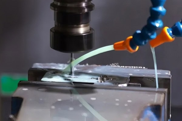
Problems Caused by Tooling and Process Settings
Tools and process parameters may seem like minor machining details, but in fact they directly determine machining efficiency, stability, and final cost, so they cannot be ignored.
Rapid Tool Wear
Short tool life directly increases machining costs and affects process stability. In batch production especially, poor tool management can create a chain of problems.
- If the material hardness is high but the tool selection is incorrect, wear will accelerate significantly, and issues such as chipping, built-up edge, and poor cutting performance may occur.
- Insufficient cutting fluid or poor chip evacuation will also increase tool wear, because cutting heat cannot be removed in time and the tool operating environment continues to deteriorate.
- Once the tool wears, both dimensional accuracy and surface quality will decline. In many cases, customers do not see a tool problem—they only see that the final part quality has worsened.
Poor tool management is one of the most easily overlooked hidden costs in CNC milling.
Unreasonable Toolpath Planning
Poor toolpath design not only slows machining, but also easily causes problems at critical positions, especially for complex surfaces and deep-cavity structures, which require higher path planning accuracy.
- Too many air-cutting moves waste machining time, causing the machine to spend a large amount of time on non-productive motion, which naturally reduces overall efficiency.
- Poor path transitions at corners can cause local overcutting, residual material buildup, or sudden changes in tool load, affecting machining stability.
- If complex surfaces are not optimized in the toolpath, the surface finish will be highly inconsistent, and the probability of rework and correction will increase.
Reasonable toolpath planning often improves overall efficiency more effectively than simply increasing spindle speed.
Mismatched Cutting Parameters
Incorrect parameter settings will damage both efficiency and quality, and may even shorten the service life of the machine and tools.
- If the spindle speed is too low, efficiency suffers and the machining cycle becomes too slow; if it is too high, it may burn the tool, generate heat, or worsen surface quality.
- Excessive feed rate may cause tool breakage, scratches, or unstable cutting, while too little feed increases friction and actually reduces efficiency.
- Different materials require different parameters. One set of parameters cannot be used for everything, because aluminum, stainless steel, copper, and engineering plastics all have very different cutting characteristics.
Whether parameter matching is reasonable directly determines whether CNC milling can achieve stable mass production.
Risks in Equipment and Operation
Machine condition and operating discipline are equally important. Many seemingly complex problems actually come from poorly controlled basic processes.
Unstable Clamping Causes Errors
Many machining problems are not caused by the machine itself, but by unreasonable clamping methods. This is especially true in batch production and complex parts, where such problems are more likely to be amplified.
- Incorrect workpiece positioning will shift all subsequent operations. Even if the program is correct, the final result may still fail to meet requirements.
- When the fixture lacks rigidity, the workpiece may move during cutting, especially under heavy cutting or strong lateral force.
- The more times a part is reclamped, the greater the cumulative error, and the lower the consistency of the parts.
Clamping stability is the first threshold for ensuring CNC milling accuracy.
Machine Vibration Affects Quality
Vibration can create surface waviness, shorten tool life, and make machining unstable. Many random quality issues are actually related to vibration.
- When machine rigidity is insufficient, high-speed cutting is more likely to cause chatter, and the tool path may deviate from the ideal state.
- Poor spindle condition can amplify machining errors, especially at high rotational speeds, where even small abnormalities become obvious.
- After long continuous machining, the thermal stability of the equipment may also decline, and thermal drift will further affect dimensions and surface quality.
If vibration is not controlled properly, many seemingly random quality problems will keep recurring.
Programming and Operational Mistakes
Even the best equipment can still scrap a part if the program is wrong, so program review and operating discipline must be in place at the same time.
- Incorrect coordinate system settings can cause the entire part to be machined off-position, and such errors usually affect a wide range of operations and are costly to correct.
- Running the machine without simulation is very risky, because many interference issues, overcuts, and path errors can be detected in advance during the simulation stage.
- When operators lack experience, they may ignore alarms, abnormal sounds, or changes in cutting conditions, missing the best time to respond.
Programming and operation errors are often the easiest mistakes to avoid, yet also the easiest to make.
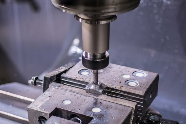
How to Reduce These Problems in CNC Milling
To truly reduce risk, you cannot just fix problems after they occur. Instead, control points must be moved forward into design, trial production, and process management so that losses can be reduced at the source.
Make the Front-End Review More Thorough
Before formal machining begins, confirming the material, structure, tolerance, and batch requirements can prevent many later rework issues and make process planning more targeted.
- For complex parts, it is recommended to conduct a process review first and confirm the machining sequence, fixture plan, and tool selection in advance to avoid frequent adjustments during production.
- Critical dimensions should have their inspection methods confirmed in advance, because different dimensions and tolerance requirements correspond to different measurement methods, and it is safer to unify the standards early.
- For batch parts, trial machining should be done before full production so that process stability can be verified first before moving into formal mass production.
The more detailed the front-end review, the more stable the CNC milling process will be later.
Process Monitoring Cannot Be Omitted
Real-time monitoring of tools, vibration, and dimensional changes during machining can help detect abnormalities in time and prevent small issues from turning into batch scrap. If tool wear is found, it should be replaced promptly; if dimensional drift occurs, parameters should be adjusted immediately; if abnormal sounds or vibration appear, the machine should be stopped for inspection right away. Good process control can intercept many batch problems before they spread.
Choose an Experienced Machining Partner
An experienced supplier can not only produce the parts, but also help customers avoid risks in advance. This is especially important for complex projects and batch orders.
- They can recommend more suitable processes based on the material instead of simply applying generic parameters, which makes stability easier to achieve.
- They can optimize toolpaths and fixtures for complex structures to reduce problems caused by deformation, vibration, and clamping errors.
- They can minimize quality risks before delivery, so customers feel more confident when receiving the parts and spend less time on follow-up communication.
Choosing the right partner often saves more money and time than fixing problems later.
Conclusion
The common problems in CNC milling may seem scattered, but in fact they are all closely related to accuracy control, tool management, process design, and operating discipline. What customers truly care about is not just whether a single part can be machined, but whether batch production is stable, whether delivery is controllable, and whether rework can be minimized. Only by identifying and solving these problems early can costs be reduced and efficiency improved. If you are looking for more stable CNC milling support, TiRapid can provide a professional and reliable manufacturing solution for your project.
















