
CNC taper turning is widely used to manufacture mechanical connectors, locating pins, shafts, valve components, and hydraulic equipment parts. Tapered surfaces support positioning, sealing, guiding, and mating connections. However, deviations in taper angle, major or minor diameter, or taper length can affect assembly accuracy and product performance. For custom precision components, taper turning requires more than accurate CNC programming. It also depends on proper tool selection, workpiece clamping, cutting parameters, and inspection methods. Understanding the key processes involved in taper turning helps improve machining consistency, reduce rework and material waste, and establish a reliable foundation for batch production and precision component sourcing.
Common Challenges and Accuracy Requirements in CNC Taper Turning
CNC taper turning uses the rotation of a workpiece and the controlled movement of a cutting tool to produce a conical surface. Taper specifications typically include the taper angle, taper ratio, major diameter, minor diameter, and taper length. These parameters are interconnected, so an error in any one of them can cause the finished profile to fall outside the drawing requirements. Compared with conventional cylindrical turning, taper turning requires greater attention to the relationship between the toolpath and the workpiece axis. Before machining, manufacturers should confirm critical dimensions, machining datums, and inspection methods based on the component geometry and tolerance requirements. This helps prevent situations where the CNC program runs correctly but the finished component still fails to assemble properly.
How Can Taper Angle, Taper Ratio, and End Diameters Be Controlled?
Dimensional control in taper turning begins with accurate drawing interpretation. An engineering drawing may specify the taper angle directly or define the taper through the major diameter, minor diameter, and taper length. Before programming, manufacturers should confirm the dimensional datums, measurement locations, and angle definition. Particular attention must be paid to the difference between the taper half-angle and the included angle of the cone. For CNC lathes using diameter programming, the coordinate settings and toolpath calculation method must also be verified to prevent errors caused by incorrect parameter interpretation.
- Verify drawing specifications: Confirm the major diameter, minor diameter, taper length, taper angle, and applicable tolerances. Check that the dimensions are internally consistent.
- Clarify the angle definition: Distinguish between the taper half-angle relative to the workpiece axis and the included cone angle. Enter the correct value according to the machine’s programming requirements.
- Establish consistent machining datums: Define the axial zero point, radial reference, and measurement locations to reduce positioning errors caused by repeated setups.
- Allow finishing stock: Leave an appropriate allowance during rough turning, then refine the profile during finishing rather than attempting to achieve final dimensions in a single cut.
- Verify critical dimensions: Measure the major and minor diameters and taper length with suitable instruments. Use dedicated taper gauges or profile measurement equipment when necessary.
Accurate parameter verification reduces program revisions and repeated trial cuts. For components with tight tolerances, the taper angle, diameters, and mating requirements should be evaluated together rather than checking a single diameter in isolation.
How Do Toolpaths and Machine Conditions Affect Taper Accuracy?
Taper turning depends on the cutting tool following a precisely defined path. Incorrect tool height, unsuitable tool-nose radius compensation, or problems with the machine’s guideways, spindle, or tool turret can cause profile deviations. Long workpieces, components with significant overhang, and insufficiently rigid clamping arrangements may also deflect under cutting forces, creating differences between the actual taper and the programmed geometry. In production, the clamping method should be selected according to workpiece length, material hardness, and cutting allowance. Before machining, operators should verify tool compensation, coordinate settings, and machine condition. For slender tapered shafts, a tailstock or other support may be necessary. For thin-walled tapered sleeves, excessive clamping pressure should be avoided to prevent deformation.
How Should Taper Turning Be Adjusted for Different Materials?
Aluminum alloys, carbon steel, stainless steel, brass, and titanium alloys differ in hardness, thermal conductivity, cutting resistance, and chip formation. They should not be machined using identical tooling and cutting parameters. Aluminum alloys generally benefit from sharp cutting edges and relatively high cutting speeds, but built-up edges and surface scratches must still be controlled. Stainless steel can work-harden during cutting, so prolonged rubbing without effective material removal should be avoided. Titanium alloys are sensitive to cutting heat and tool condition, requiring parameters tailored to the specific grade, tooling recommendations, and machine capabilities. Engineering plastics also require attention to thermal expansion, clamping deformation, and measurement temperature. Matching the machining process to the material helps reduce taper variation and improve surface quality.
How to Optimize CNC Taper Turning Processes
A stable taper turning process combines tool selection, CNC programming, cutting parameters, and workholding methods. Rough turning removes material efficiently and establishes the basic profile, while finishing operations control final dimensions, surface continuity, and roughness. For components with long tapers, narrow tapered features, or demanding mating requirements, process planning should also consider tool accessibility, chip evacuation, and ease of measurement. A well-planned machining sequence, followed by first-article verification and necessary parameter adjustments, helps reduce dimensional variation during batch production.
How to Choose the Right Tool for CNC Taper Turning
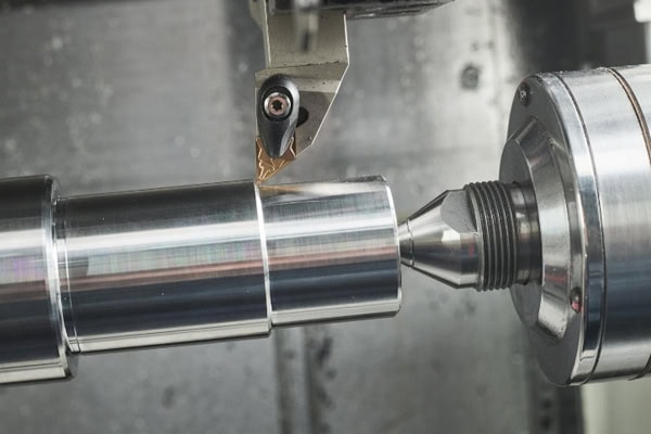
Tool selection should be based on workpiece material, taper length, machining allowance, feature location, and required surface quality. External tapers can generally be machined using tools suitable for external profiling, while internal tapers require careful consideration of boring bar diameter, overhang, and chip evacuation inside the bore. Insufficient tool rigidity can cause chatter and profile deviations. Incorrect tool-nose geometry may lead to overcutting, poor surface finish, or localized residual material. For batch production, tool replacement efficiency and the ability to compensate for wear-related dimensional changes should also be considered.
- Select tools according to feature location: Use suitable external profiling tools for external tapers. For internal tapers, choose boring tools based on bore diameter, depth, and toolholder overhang.
- Match inserts to the material: Select insert grades, coatings, and edge geometries according to material hardness, toughness, and cutting temperature.
- Verify tool-nose radius compensation: Configure compensation according to the actual tool geometry to prevent dimensional errors at profile transitions.
- Improve tool rigidity: Minimize unnecessary toolholder overhang while maintaining adequate access to the machining area, reducing vibration and deflection.
- Establish tool life standards: Record the number of parts machined, wear conditions, and dimensional changes to determine appropriate inspection and replacement intervals.
Proper tool and material matching improves machining stability and reduces taper variation caused by tool wear. For batch orders, first-article inspection and in-process sampling can help determine whether tool compensation or replacement is necessary.
How Can Cutting Parameters and Toolpaths Be Optimized?
Cutting speed, feed rate, and depth of cut should be adjusted according to workpiece material, tool performance, machine rigidity, and machining stage. During rough turning, a suitable depth of cut can improve material removal efficiency, provided that the cutting load remains within the limits of the machine and tool. Finishing operations generally require more stable cutting conditions to control taper dimensions and surface quality. CNC toolpaths should guide the tool safely into and out of the cutting area while avoiding collisions and unnecessary tool marks at entry, exit, or profile transitions. For complex tapers or components with multiple tapered sections, simulation is recommended before machining begins, followed by dimensional verification of the first part. Cutting parameters should not be increased solely to achieve higher speed. Chip formation, tool wear, vibration, and surface patterns should also be monitored to establish a stable combination of parameters for the specific machine and material.
How Can Chatter, Burrs, and Surface Defects Be Reduced?
Chatter marks, burrs, scratches, and uneven dimensions on tapered surfaces are often associated with tool wear, insufficient workholding rigidity, unsuitable cutting parameters, poor chip evacuation, or inconsistent machining allowance. Chips that repeatedly contact a finished surface can create fine scratches, while insufficient workpiece rigidity can cause vibration as cutting forces change. Production teams should maintain sharp cutting edges, inspect workholding conditions, and select appropriate cooling and chip evacuation methods for the material. For precision tapers, feed rate or depth of cut should not be increased before tool condition and workholding stability have been confirmed.
- Check clamping and support: Ensure secure workholding and add auxiliary support when necessary to reduce deflection in slender components.
- Maintain consistent tool condition: Inspect inserts for wear, chipping, and built-up material to prevent tool condition changes from affecting the taper profile.
- Improve chip evacuation and cooling: Remove chips from the cutting zone promptly to reduce chip entanglement, recutting, and surface scratching.
- Plan finishing operations carefully: Leave a uniform allowance after rough turning to prevent sudden changes in cutting load.
- Control deburring operations: Remove burrs from taper edges without damaging critical mating surfaces or changing functional dimensions.
Standardized operating procedures and in-process checks can reduce the occurrence of taper surface defects. If chatter or dimensional deviations repeatedly appear in the same location, investigate machine condition, tool overhang, workpiece rigidity, and the programmed toolpath rather than relying solely on a lower feed rate.
Quality Inspection and Custom Sourcing for CNC Taper Turning
The acceptance of a tapered component depends on more than its appearance or an individual diameter. Inspection should consider the taper angle, taper length, mating condition, and dimensional tolerances specified in the engineering drawing. An appropriate inspection plan helps manufacturers identify programming or workholding issues during first-article verification and monitor dimensional changes caused by tool wear during batch production. For custom machining projects, buyers should provide complete drawings, material specifications, surface treatment requirements, and order quantities so the manufacturer can assess process feasibility, inspection methods, and delivery arrangements. Clear technical information improves quotation accuracy and reduces the cost of subsequent communication and revisions.
How Should Taper Dimensions and Surface Quality Be Inspected?
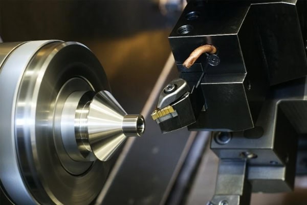
Inspection methods should be selected according to component size, tolerance requirements, and taper geometry. Standard measuring instruments can verify certain diameters and lengths, but calipers alone are often insufficient to determine whether a taper angle or tapered mating feature meets the complete specification. Depending on the drawing, inspection may involve micrometers, bore gauges, dedicated taper gauges, profile measurement equipment, or coordinate measuring machines. Measurement locations, temperature, and reference conditions should be consistent. This is particularly important for plastic or thin-walled components, where temperature changes and clamping forces can affect dimensions. Surface quality can be evaluated through visual inspection or a surface roughness tester, depending on the specified requirements. The finished taper should be free of significant scratches, chatter marks, burrs, and other defects that could interfere with mating performance. For batch orders, first-article inspection, in-process sampling, and final inspection records should be maintained so dimensional trends can be identified and traced.
How to Choose a Precision CNC Taper Turning Supplier and Obtain an Accurate Quote
When selecting a custom machining supplier, buyers should evaluate more than the unit price. The supplier should understand the taper definition, mating tolerances, and inspection requirements shown in the engineering drawing. The more complete the quotation information, the lower the risk of cost differences caused by incorrect process assumptions. For prototype and batch production projects, clarify the quantity, material, finishing requirements, inspection documentation, and delivery schedule during the quotation stage.
- Provide complete engineering drawings: Submit drawings that specify dimensions, tolerances, taper angles, surface roughness, and datum requirements. Include a 3D model when necessary.
- Specify material and quantity: Confirm the material grade, heat treatment condition, prototype quantity, and expected production volume so tooling, process planning, and cycle time can be evaluated.
- Confirm inspection and acceptance criteria: Explain whether critical dimensions require dedicated gauges, coordinate measurement, or inspection reports to prevent differences in interpretation at delivery.
- Compare total manufacturing costs: Consider programming and setup, material utilization, tool consumption, finishing, and inspection costs instead of focusing only on the initial quote.
- Evaluate supplier communication: Prioritize suppliers that can provide manufacturability recommendations based on the drawings and clearly explain process limitations and quality control methods.
When requesting a quotation from CNC machining providers such as TiRapid, prepare the component drawings, material specifications, order quantity, and quality requirements. Ask the machining team to evaluate the process route and quotation conditions. For critical taper dimensions, confirm the inspection method and acceptance criteria before placing the order so prototype validation, batch machining, and final delivery remain consistent. Thorough technical communication helps control costs, shorten adjustment cycles, and obtain precision-turned components that meet actual assembly requirements.
















