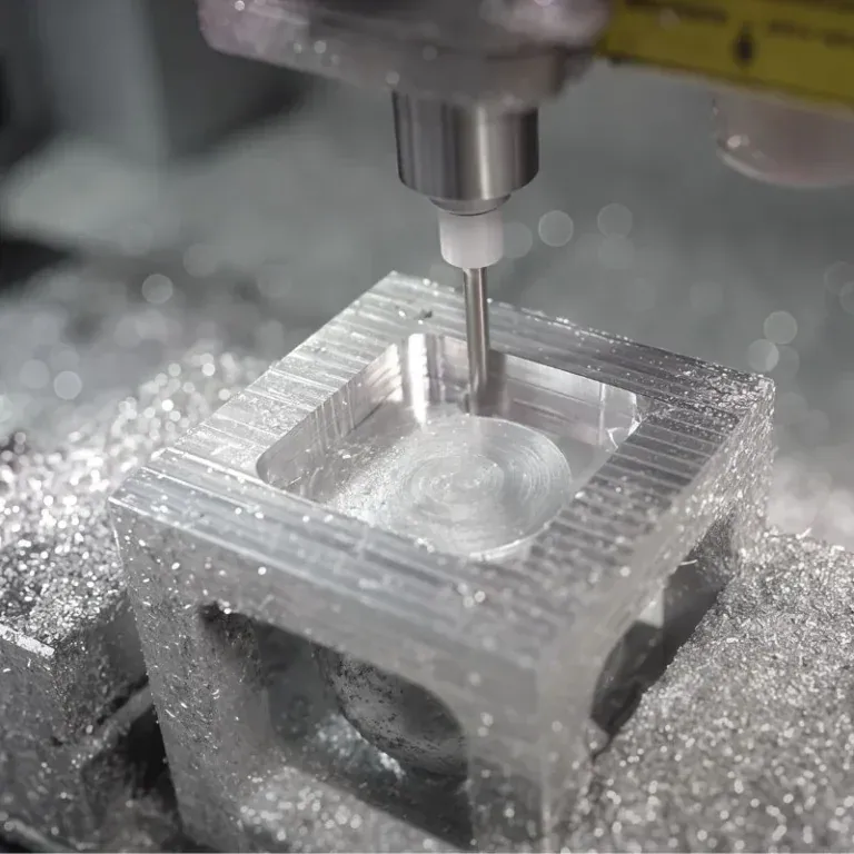
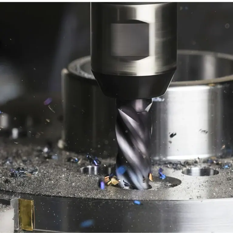
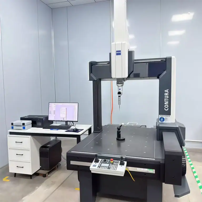
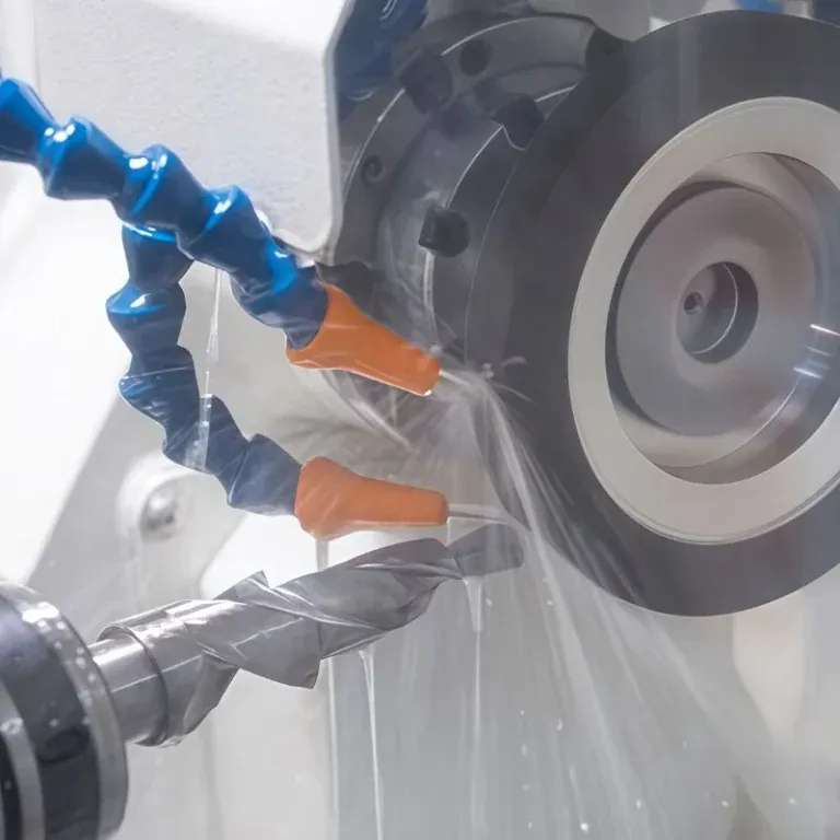
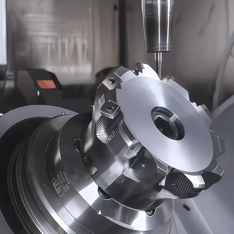
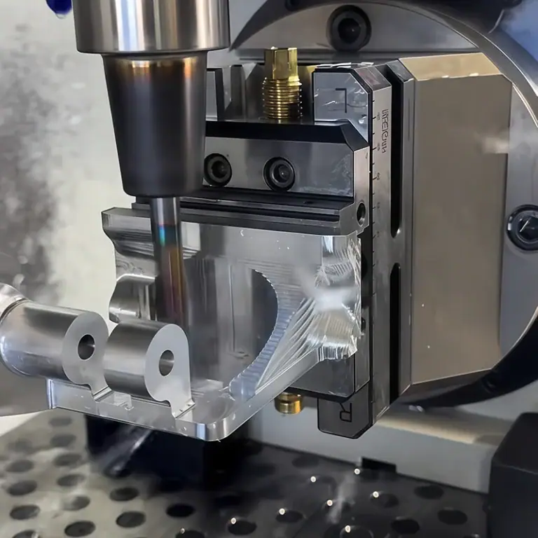
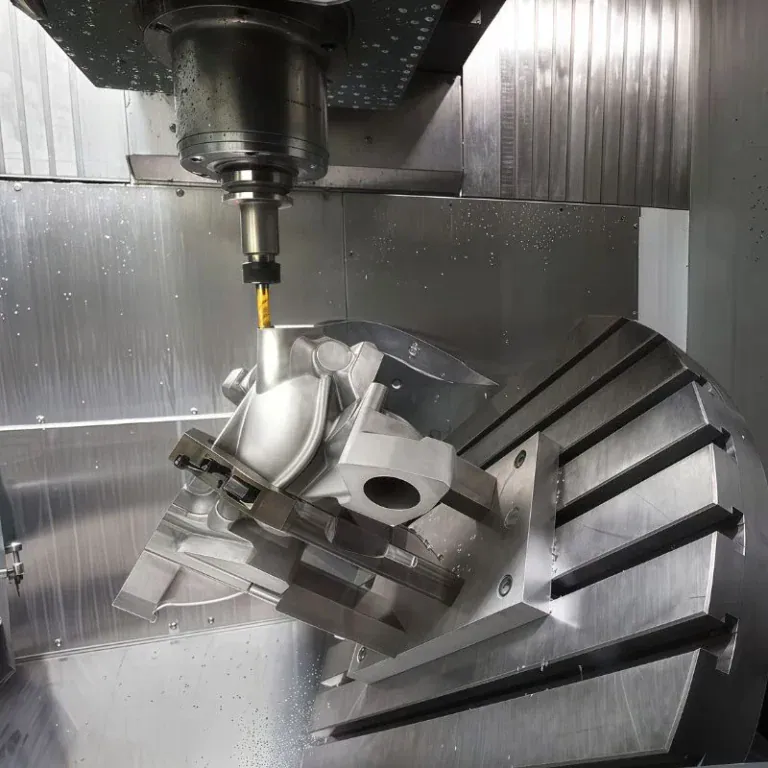
Copper components may be relatively small, but a few critical holes, mating surfaces, or threaded features can have a major impact on industrial equipment performance. Electrical terminals require accurate dimensions, cooling components need well-designed structures, and valve fittings or precision bushings must fit correctly during assembly. Conventional machining can work well for simple parts, but complex contours, multiple holes, and tight tolerances can make repeated setups and manual adjustments more likely to introduce errors. CNC machining uses programmed toolpaths to control cutting operations, helping achieve complex geometries, precise dimensions, and repeatable results. It is well suited to custom copper parts for industrial equipment, prototype development, and batch production, making the process from engineering drawings to finished components more predictable.
What Are the Advantages of Copper CNC Machining for Precision Industrial Parts?
Copper components for industrial equipment often require several features to be machined, including outer profiles, holes, threads, and stepped surfaces. If each feature requires separate positioning and manual finishing, machining time can increase and dimensions may vary between production batches. CNC machining uses programmed toolpaths to coordinate multiple features within a planned process, improving repeatability while meeting drawing requirements.
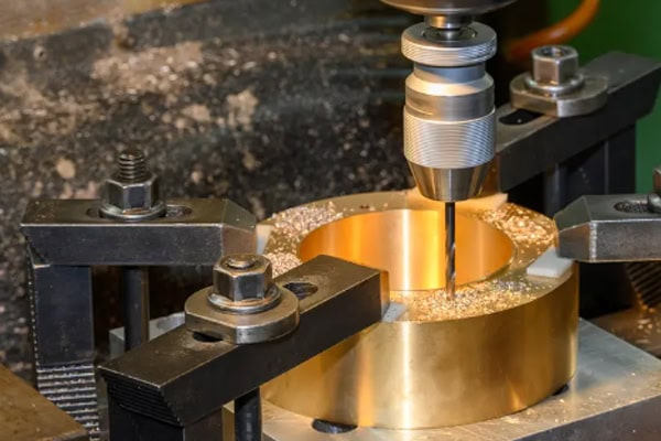
How Does CNC Machining Improve Dimensional Accuracy in Copper Parts?
Precision copper machining involves more than producing holes to a specified diameter. Hole spacing, positional accuracy, and mating relationships must also meet the required tolerances. CNC machining follows programmed coordinate references, reducing errors caused by manual marking and repeated positioning.
- Better control of precision holes: Mounting holes, locating holes, and threaded holes can be machined according to engineering drawings, reducing the risk of assembly misalignment.
- Greater flexibility for complex contours: Steps, grooves, and irregular profiles can be machined using suitable toolpaths, reducing the need for manual finishing.
- More consistent repeat orders: Validated CNC programs can be reused for subsequent production, reducing repeated setup adjustments and programming work.
This repeatability is particularly valuable for industrial equipment that uses the same copper components over an extended period. When combined with inspections of critical dimensions, CNC machining can reduce assembly adjustments and help parts meet their intended functional requirements.
Can Copper CNC Machining Shorten Prototyping and Development Time?
Custom components often require changes to hole positions, outer profiles, or mounting interfaces. If every design revision requires complex tooling to be remade, development can take longer. CNC machining allows toolpaths to be adjusted digitally, making it suitable for new product development and custom part prototyping.
- Tooling, fixturing, and machining sequences can be evaluated once the engineering drawing or 3D model is available.
- Prototype parts can be checked for fit and assembly, with dimensions or features revised as needed.
- Once the prototype is approved, the validated machining program can be carried forward into subsequent production.
Which Copper Components for Industrial Equipment Can Be CNC Machined?
Copper is used in a wide range of applications, and different components have different requirements for electrical conductivity, wear resistance, and dimensional accuracy. When the material, geometry, and machine capabilities are properly matched, CNC machining offers a flexible solution for custom copper components.
Common applications include electrical terminals, precision connectors, cooling components, valve fittings, copper bushings, and custom mechanical parts. For components with complex structures or tight tolerances, critical dimensions and tool accessibility can be evaluated before machining to establish a suitable manufacturing process.
Which Copper Materials Are Used in CNC Machining, and How Should You Choose?
Choosing the right copper material affects component performance as well as machining costs. Pure copper is commonly used in electrical and thermal applications, brass is widely used for fittings and threaded components, and bronze is often selected for wear-resistant parts such as bushings. Material selection should go beyond the general material name and include the specific grade, operating environment, fit requirements, and any planned surface treatments.
What Is the Difference Between Pure Copper, Brass, and Bronze?
| Copper Material | Common Applications | Machining Characteristics and Selection Considerations |
| Pure copper | Electrical terminals, connectors, cooling components | Offers good electrical and thermal conductivity; burrs and surface scratches require attention |
| Brass | Valves, pipe fittings, threaded connectors | Generally offers good machinability; the specific grade should be confirmed |
| Bronze | Bushings, sleeves, wear-resistant components | Suitable for certain wear applications; mating dimensions and material properties need to be considered |
| Specialty copper alloys | Custom industrial components and specialized parts | Machining processes should be evaluated based on composition and intended use |
Once the material is confirmed, the CNC machining process can be adjusted accordingly. Different copper materials behave differently during cutting. Specifying the correct grade in advance helps determine suitable tooling and cutting parameters, reducing unnecessary trial machining.
What Information Is Needed for a Custom Copper CNC Machining Quote?
To obtain a useful machining quote more quickly, the manufacturing requirements need to be clearly defined. A part photograph or approximate dimensions alone may not provide enough information to evaluate tolerances, machining complexity, or inspection requirements.
- Engineering drawings or 3D models: Show the external profile, hole positions, steps, and internal features.
- Material grade and tolerances: Specify the copper grade and tolerances for critical dimensions.
- Surface treatment requirements: State whether plating, polishing, or other finishing processes are required.
- Quantity and lead time: Provide the prototype quantity, expected production volume, and target delivery date.
Complete technical information makes it easier to evaluate machining operations, inspection methods, and production scheduling while reducing repeated communication during the quoting process.
How Can Copper CNC Machining Reduce Costs and Maintain Batch Quality?
Copper machining costs depend on more than material prices and cutting time. Part complexity, the number of setups, tolerance requirements, and additional surface treatments can all affect the final quote. For industrial components that require ongoing production, a well-planned process can reduce repeated operations and rework while balancing production efficiency with batch consistency.
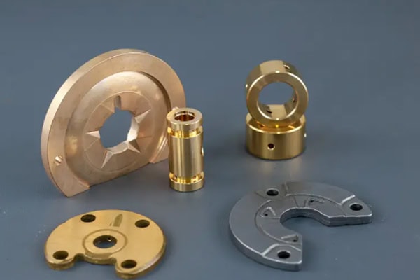
How Can CNC Machining Reduce Copper Part Manufacturing Costs?
- Fewer repeated setups: Organizing machining operations efficiently reduces repositioning errors and non-cutting time.
- Optimized toolpaths: Selecting suitable strategies for profiles, holes, and grooves reduces unnecessary tool movement.
- Controlled tool wear: Adjusting cutting parameters to suit copper helps reduce built-up material on cutting edges, burrs, and abnormal tool wear.
- Less rework: Planning inspection checkpoints for critical dimensions helps identify machining deviations earlier.
Higher cutting speeds do not automatically mean lower overall costs. Unsuitable tooling or poor control of critical dimensions can increase finishing work and scrap. Evaluating machining efficiency, dimensional accuracy, and finished-part quality together provides a more practical way to control manufacturing costs.
What Should Be Inspected During Batch Production of Copper Parts?
Batch production must deliver more than an acceptable first part. Subsequent components also need to maintain consistent dimensions. First-article inspection, in-process sampling, and final inspection can work together, with the specific checks determined by drawing tolerances and the intended application.
| Inspection Item | Key Checks | Purpose |
| Overall dimensions | Length, thickness, and step dimensions | Confirm compliance with engineering drawings |
| Hole accuracy | Diameter, spacing, and positional tolerances | Ensure correct mounting and fit |
| Thread quality | Thread specification, depth, and profile | Support reliable assembly |
| Surface condition | Burrs, scratches, and machining marks | Improve appearance and functional quality |
For copper parts with tight tolerances or complex geometries, additional measurements can be planned for critical features. Inspection results can also help identify tool wear or process changes, reducing the chance of recurring defects in later production runs.
How Can Copper Parts Move Smoothly from Prototyping to Batch Production?
Prototyping should verify more than whether a component can be machined. Fit, critical dimensions, and surface requirements also need to be confirmed. Once a prototype is approved, carrying validated CNC programs, fixturing methods, and inspection standards into production helps minimize repeated trial and error.
- Check hole positions, threads, and mating features against assembly requirements after prototype machining.
- Inspect the first production part before releasing the full batch, adjusting the process if deviations are found.
- Monitor critical dimensions during production and conduct sampling or full inspection as required.
- Check burrs, surface condition, and other drawing requirements before delivery.
For industrial equipment components that need regular replenishment or ongoing production, a well-managed transition from prototyping to batch manufacturing can reduce repeated development costs and help maintain consistency across future orders.
Copper CNC machining supports more than precision holes and complex contours. It also enables custom industrial component development, prototype validation, and batch manufacturing. With appropriate material selection, optimized toolpaths, and inspection of critical dimensions, manufacturers can improve machining efficiency, reduce assembly rework, and produce copper components that better meet their intended applications. If you are developing parts made from pure copper, brass, bronze, or other copper alloys, contact TIRAPID with your engineering drawings, material grade, tolerance requirements, and order quantity to discuss a suitable CNC machining solution and request a quote.