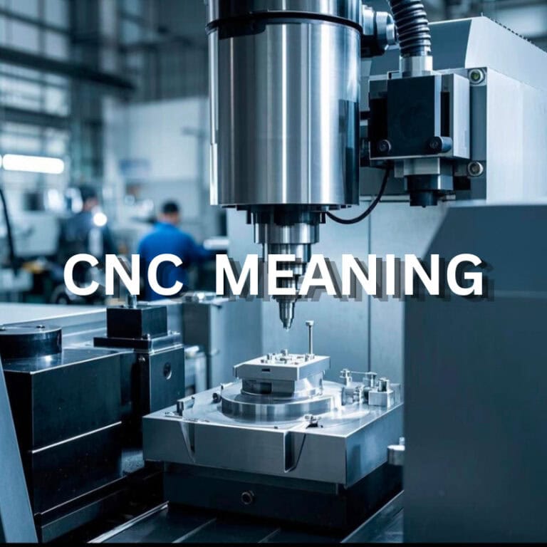
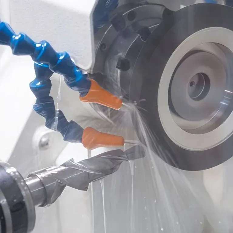
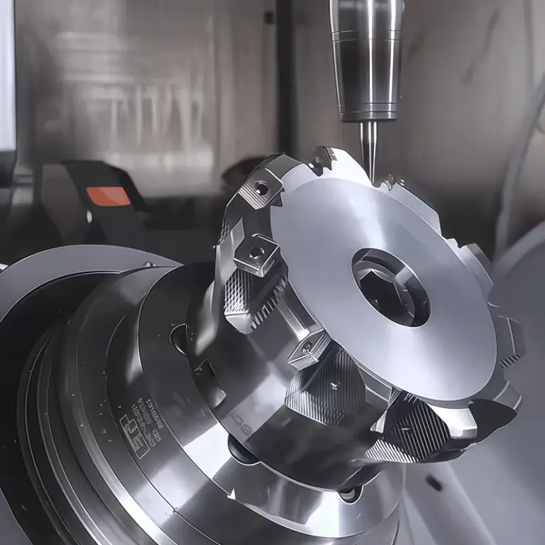
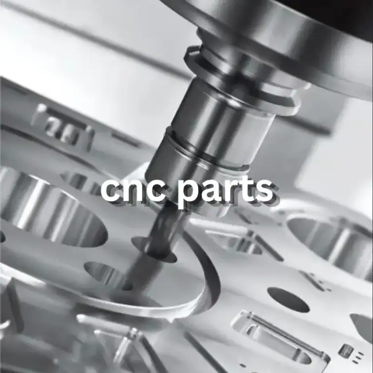
Automated electronic equipment components, including mounting brackets, sensor holders, heat sink bases, and precision fixtures, have different requirements for dimensional accuracy, assembly positioning, and material properties. Machining deviations can affect equipment installation, electronic component positioning, and heat dissipation, increasing subsequent adjustment and maintenance costs. When selecting CNC machining services, manufacturers should evaluate not only pricing and lead times but also material suitability, surface finishing, deformation control, and inspection capabilities. Developing a machining plan based on component functions helps improve assembly consistency and reduce quality risks during prototyping and batch production.
Machining Requirements for Automated Electronic Equipment Components
Different components serve different functions, so machining plans should be developed according to their structural features, operating environments, and assembly requirements.
Structural Accuracy and Assembly Fit
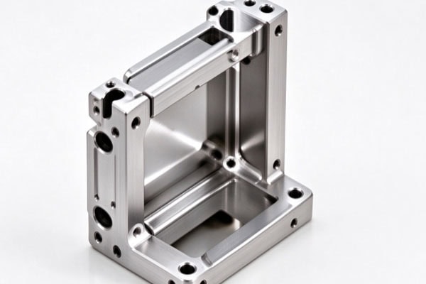
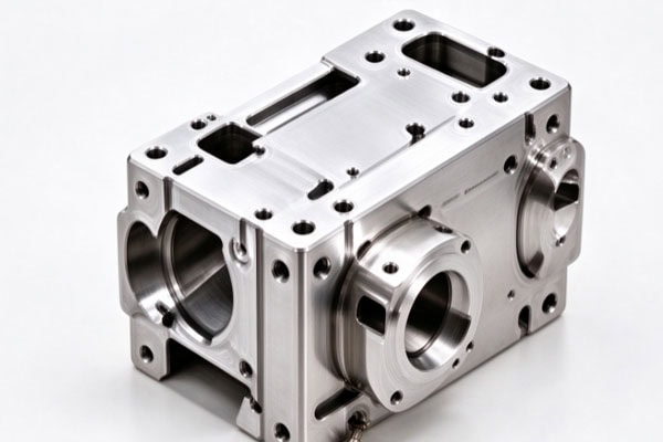
Electronic equipment components often include mounting holes, locating surfaces, slots, and connection features. The dimensional relationships between these features directly affect assembly accuracy.
- Mounting and Positioning: Control hole diameters, hole spacing, and datum locations according to engineering drawings to ensure compatibility with mating components.
- Complex Structures: Plan toolpaths for thin walls, narrow slots, and multi-face features to reduce the risk of tool interference and localized deformation.
- Heat Dissipation Components: Heat sink bases require attention to flatness, contact surface quality, and the dimensions of heat dissipation features to maintain effective heat transfer.
Relating critical dimensions to actual assembly functions helps reduce rework and on-site adjustments.
Material Selection and Machining Compatibility
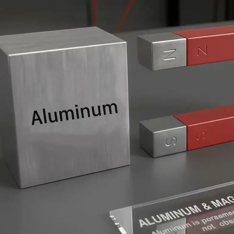
Materials should be selected according to load-bearing capacity, thermal conductivity, insulation requirements, and operating conditions. Aluminum alloys are suitable for heat sink bases, mounting plates, and structural components when their strength and rigidity meet design requirements. However, removing large amounts of material can release residual stress and cause warping. Stainless steel and other steels can be used for components requiring strength, wear resistance, or corrosion resistance, although cutting difficulty and surface quality must be considered. Engineering plastics such as POM and nylon may be suitable for insulating supports and fixtures. During machining, cutting heat, clamping force, moisture absorption, and residual stress must be controlled to limit dimensional changes.
CNC Machining Process and Surface Finishing Planning
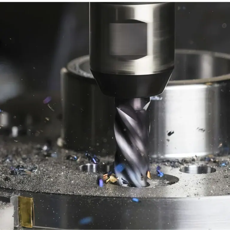
A well-planned machining sequence and clearly defined post-processing requirements help control final dimensions and prevent components from meeting machining specifications but failing during assembly.
Control Deformation in Heat Sink Bases and Thin-Walled Components
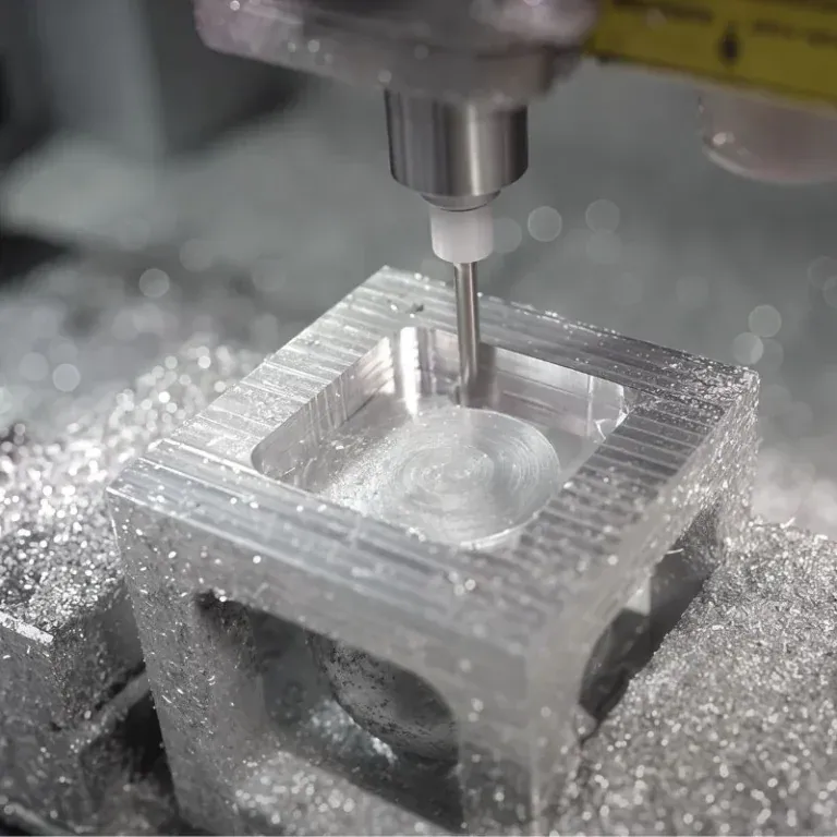
Aluminum alloy heat sink bases and thin fins may be affected by residual stress, clamping force, and cutting heat during machining. Process planning should account for these factors based on the component’s geometry.
- Staged Machining: Separate rough machining from finish machining and, when necessary, include intermediate stabilization to reduce dimensional changes caused by stress release.
- Proper Workholding: Select clamping positions and forces according to component rigidity to avoid excessive pressure on thin-walled areas.
- Reinspection of Critical Dimensions: Pay particular attention to large flat surfaces, thin walls, and thermal contact surfaces. Recheck flatness after machining and stabilization when required.
Stress-relief treatment is not a mandatory step for every aluminum alloy component. Its necessity should be determined by material condition, machining allowance, and accuracy requirements.
Define Surface Finishing and Dimensional Compensation in Advance
Processes such as anodizing and painting may affect external dimensions and mating conditions. These requirements should be confirmed before CNC machining begins.
- Anodizing: Evaluate dimensional changes to hole diameters, external profiles, and mating surfaces based on the specified coating thickness and growth characteristics. Adjust machining dimensions when necessary.
- Painting: Plan dimensional allowances according to coating thickness and assembly requirements, and define masking areas for threaded holes, precision holes, and mating surfaces.
- Appearance and Functional Requirements: Specify treatment areas and acceptance criteria for surfaces requiring electrical conductivity, insulation, or a particular appearance.
Including surface finishing in the initial process plan helps reduce the risk of dimensional deviations after post-processing.
Quality Inspection and Critical Dimension Control
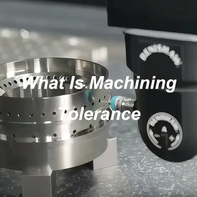
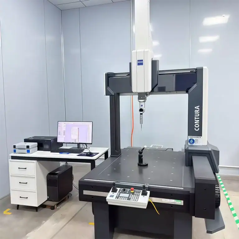
Inspection procedures should be based on component functions, drawing tolerances, and final acceptance requirements, with particular attention to features affecting assembly, positioning, and heat dissipation.
Define Inspection Items
Different component types require different inspection priorities. Measuring only overall dimensions may overlook critical functional requirements.
| Component Type | Key Inspection Items | Inspection Purpose |
| Mounting Brackets and Locating Components | Hole diameters, hole spacing, and positional tolerances | Ensure accurate mounting and positioning |
| Aluminum Alloy Heat Sink Components | Flatness, contact surfaces, and heat dissipation feature dimensions | Meet assembly and heat dissipation requirements |
| Engineering Plastic Fixtures | Critical dimensions, hole positions, and deformation | Maintain stable positioning and operation |
| Surface-Finished Components | Coating or film requirements and final dimensions | Prevent interference with fit and function |
| Precision Structural Components | Overall dimensions, datum relationships, and surface quality | Meet drawing and assembly requirements |
Inspection methods should match component geometry and accuracy requirements. Appropriate measuring equipment should be used when necessary to verify critical features.
Monitor Dimensional Stability After Machining
Some aluminum alloy and engineering plastic components may undergo dimensional changes after machining. Acceptance decisions should account for material properties and intended applications. For large flat surfaces, thin-walled structures, and high-precision mating features, staged measurements or reinspection after stabilization may be appropriate. Recording critical dimensions and investigating deviations helps improve consistency across production batches.
How to Choose a CNC Machining Supplier for Automated Electronic Equipment
Supplier selection should consider material processing capabilities, experience with complex structures, coordination of surface finishing, and quality management. Although pricing and lead times are important, the supplier’s ability to understand the actual functional requirements of each component also affects total procurement costs.
Evaluate Machining Capabilities and Process Control
Different components require different equipment and technical controls. Before placing an order, confirm that the supplier can handle the required materials and structural features.
- Equipment and Precision: Determine whether the supplier can meet critical dimensional, complex contour, and flatness requirements.
- Material Processing Experience: Confirm relevant experience in controlling aluminum alloy deformation and precision machining engineering plastics.
- Post-Processing Coordination: Verify the supplier’s ability to coordinate anodizing, painting, and other required surface treatments.
Clearly defining machining capabilities and process limitations helps reduce prototype failures and batch rework.
Provide Complete Technical Documentation and Acceptance Requirements
Clear engineering documentation enables accurate assessments of machining complexity, quotation costs, and production schedules.
- 2D Engineering Drawings and 3D Models: For complex components, provide both whenever possible. Use drawings to specify technical requirements and models to support geometric analysis and CNC programming.
- Specify Critical Requirements: Clearly define material specifications, dimensional tolerances, threads, surface roughness, and surface finishing requirements.
- Confirm Order Conditions: Provide order quantities, delivery schedules, and inspection requirements. If information is incomplete, resolve the missing details before production begins.
Complete documentation helps reduce repeated communication and acceptance disputes.
The machining quality of automated electronic equipment components depends on coordinated material selection, dimensional control, deformation management, and surface finishing. Manufacturers should define requirements according to each component’s assembly, heat dissipation, and insulation functions, and confirm critical tolerances and acceptance criteria before production. TiRapid provides customized precision CNC machining services and helps develop suitable manufacturing solutions based on customer drawings, material requirements, and order specifications.