Robot reducers are critical transmission units used in robotic joints to reduce input speed, increase output torque, and achieve precise motion control. Their internal components commonly include reducer housings, input shafts, output shafts, flanges, shaft sleeves, bearing seats, connection plates, eccentric components, and other precision mechanical parts. During continuous robotic operation, reducer components are exposed to alternating loads, impact loads, and repeated rotational movement. As a result, dimensional accuracy, concentricity, radial runout, surface roughness, and assembly fit can directly influence the stability and service life of the robotic joint. CNC precision machining can process different reducer components through turning, milling, drilling, boring, tapping, finishing, and multi-axis machining. These processes provide reliable dimensional control for shafts, discs, housings, flanges, and other precision structures. For industrial robots, collaborative robots, SCARA robots, and automated robotic arms, customized CNC machining can also adapt component dimensions to different reduction ratios, load capacities, mounting interfaces, and joint structures, providing high-consistency mechanical components for robot transmission systems.
CNC Machining Processes and Manufacturing Advantages for Robot Reducer Components
Robot reducer components require accurate relationships between mating parts. A component meeting its individual dimensional requirements does not necessarily guarantee stable performance after assembly. Shafts and bearings, housings and bearing seats, output flanges and shafts all need to maintain accurate geometric relationships. Mounting holes and positioning structures must also meet the required assembly tolerances. CNC machining uses digitally controlled tool movements to produce complex profiles, precision holes, and rotationally symmetrical structures with repeatable accuracy. Different operations can share consistent machining datums, reducing dimensional variation between production batches and improving component interchangeability. This manufacturing method is suitable for prototype development, small-batch customized production, and volume manufacturing of robot reducer components.
Precision CNC Machining Process for Robot Reducer Components
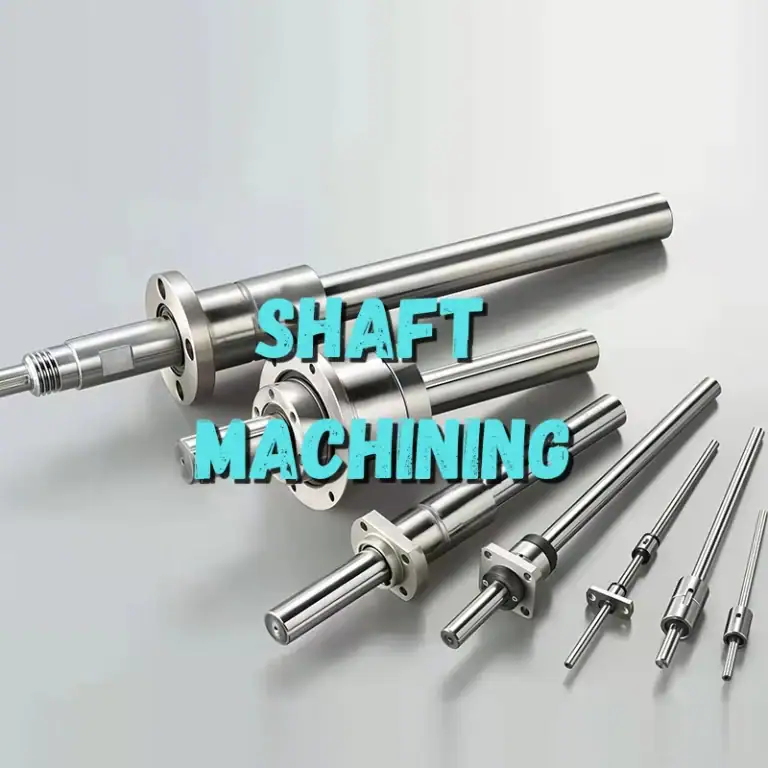
Different reducer components require different machining strategies. Input shafts and output shafts are typically manufactured through CNC turning to produce external diameters, steps, end faces, grooves, and threads. Additional finishing operations may be applied to bearing seats and precision mating surfaces according to assembly requirements. Reducer housings and connection flanges are commonly processed through CNC milling, boring, and drilling to maintain accurate relationships between mounting surfaces, bearing bores, and bolt holes.
For bearing seats requiring high concentricity, rough boring and finish boring can be separated into different operations. This helps reduce dimensional deviations caused by excessive material removal in a single pass. Thin-wall housings require carefully designed fixturing and clamping forces to prevent deformation during machining. Complex flanges, eccentric components, and multi-hole disc-shaped parts can be manufactured using four-axis or five-axis machining to reduce repeated setups and maintain consistent positioning between features.
Robot reducer components may also contain chamfers, relief grooves, sealing grooves, and threaded structures. Proper tool selection and cutting parameter optimization can improve surface quality while reducing burrs that could interfere with subsequent assembly.
CNC Machining Workflow for Robot Reducer Components
The machining workflow for reducer components should be determined according to component type, material, tolerance requirements, and final assembly specifications. A controlled production sequence helps maintain critical dimensions between operations while minimizing positioning errors caused by repeated clamping.
A typical CNC machining workflow includes:
- Engineering drawing verification: Confirm dimensions, tolerances, materials, heat treatment requirements, surface roughness, and critical mating dimensions.
- Raw material preparation: Select bar stock, forgings, castings, or pre-machined blanks according to shaft, disc, or housing structures.
- Datum establishment: Machine stable end faces, external diameters, or locating surfaces to create reliable reference datums.
- Rough machining: Remove most of the material efficiently while forming the basic component geometry and maintaining sufficient finishing allowance.
- Finish machining: Precisely machine bearing seats, mating diameters, mounting surfaces, positioning holes, and sealing structures.
- Hole machining: Produce bearing bores, bolt holes, locating holes, lubrication passages, and threaded holes.
- Deburring and surface treatment: Remove sharp edges and machining burrs before applying anodizing, plating, passivation, or other specified treatments.
- Dimensional and assembly inspection: Check critical dimensions, concentricity, radial runout, hole spacing, and surface quality, followed by assembly verification when required.
A stable CNC production workflow helps maintain dimensional consistency between different production batches. For precision transmission components, first-piece approval and in-process inspection are particularly important.
Common Materials and Performance of Robot Reducer Components
Reducer components must be manufactured from materials suitable for their load, rotational speed, wear requirements, and structural weight. Material selection also affects cutting tools, machining parameters, and subsequent surface treatment.
| Material | Typical Performance | Common Applications |
| 6061-T6 Aluminum Alloy | Lightweight, machinable, corrosion resistant | Reducer housings, connection flanges |
| 7075-T6 Aluminum Alloy | High strength and low weight | High-load connection and support components |
| 40Cr Steel | High strength and suitable for heat treatment | Shafts, transmission components |
| 45 Steel | Stable mechanical properties and good machinability | Shafts, flanges, support components |
| Stainless Steel | Corrosion resistance and stable mechanical performance | Specialized housings and shafts |
| Copper Alloys | Good thermal conductivity and wear resistance | Bushings, guide structures, specialized mating components |
Material selection should be based on reducer structure, operating load, and working environment. For high-speed rotating or heavily loaded components, material strength and heat treatment condition can have a significant effect on service life.
Applications, Usage Methods, and Functional Performance of Robot Reducer Components
Robot reducers are primarily installed in rotary joints and motion axes to reduce motor speed, increase output torque, and control robotic movement with high precision. Different robot joints have different loads, motion ranges, and space limitations, creating different requirements for reducer components. Compact collaborative robots often prioritize low component weight and space efficiency, while large industrial robots require higher load capacity and impact resistance. Customized CNC machining enables reducer components to be manufactured according to the specific dimensions, mounting interfaces, and transmission architecture of each robotic joint.
Typical Applications of Robot Reducer Components
Robot reducer components are widely used in industrial robots, collaborative robots, SCARA robots, palletizing robots, welding robots, and automated robotic arms. Reducers often operate under high-frequency movement, so their components must maintain stable mechanical properties throughout repeated operating cycles.
Typical applications include:
- Industrial robot joints: Used in large-load robotic arms to provide stable transmission structures for shoulder, elbow, and wrist joints.
- Collaborative robots: Compact reducer structures require lightweight housings, connection flanges, and high-precision shafts.
- SCARA robots: Horizontal rotary joints require high concentricity for shafts, flanges, and bearing seats.
- Palletizing robots: Repetitive high-speed handling operations require reducer components with good fatigue resistance.
- Welding robots: Continuous operation requires stable output movement and reliable transmission fits.
- Automated machinery: Customized automation systems can use different reducer components according to their specific loads and motion requirements.
Different robotic systems have different requirements for reducer component dimensions, strength, and accuracy. CNC customization allows each component to be manufactured according to the specific structure of the robot joint.
Usage Methods and Structural Functions of Robot Reducer Components
Robot reducer components normally work together with bearings, gears, seals, motors, and joint housings to form a complete transmission assembly. During installation, shaft components must be positioned correctly to ensure that bearing seats, sealing surfaces, and output connection structures remain properly aligned. Flanges and housings are commonly secured using locating pins, screws, or precision mating structures to prevent significant displacement during robotic movement.
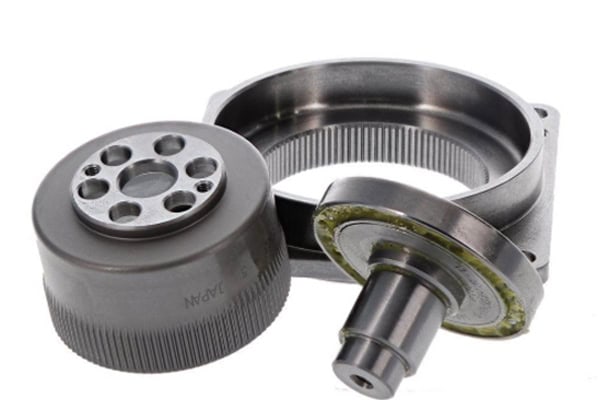
The reducer housing supports and protects the internal transmission mechanism. The bearing seat maintains the position of rotating components, while the input shaft connects to the motor and transfers mechanical power. The output shaft transfers the reduced speed and increased torque to the robot joint. Connection flanges secure the reducer to the robotic structure, while shaft sleeves and bushings can improve wear resistance in specific mating areas.
During operation, installation torque, lubrication procedures, and maintenance intervals should follow the equipment manufacturer’s specifications. Mounting screws, sealing structures, and transmission components should also be checked regularly. Accurate component dimensions and reliable assembly relationships can help reduce abnormal vibration and noise during operation.
Functional and Performance Requirements for Robot Reducer Components
Reducer components must withstand continuous rotation, alternating loads, and occasional impact loads. Dimensional accuracy and mechanical strength must meet the requirements of the transmission system. Bearing bore geometry affects bearing installation, shaft concentricity influences rotational stability, and flange hole positioning affects the assembly accuracy of the entire robotic joint.
| Function / Performance | Key Requirement | CNC Machining Requirement |
| Torque Transmission | Withstand continuous and peak loads | Stable dimensions for shafts and connection structures |
| Rotational Accuracy | Reduce runout and abnormal vibration | Control concentricity, radial runout, and roundness |
| Bearing Installation | Maintain stable bearing positioning | Precision bearing bores and mating surfaces |
| Structural Strength | Withstand joint loads | Proper material selection, wall thickness, and reinforcement |
| Sealing Performance | Reduce lubricant leakage and contamination | Accurate sealing grooves and mating areas |
| Mounting Accuracy | Maintain precise robot joint positioning | Accurate flange hole spacing and locating holes |
| Wear Resistance | Support long-term cyclic movement | Appropriate materials and surface treatments |
| Thermal Stability | Minimize dimensional changes caused by temperature | Controlled material condition and machining allowance |
These performance requirements collectively affect the transmission stability of the reducer. Precision CNC machining can provide robot joints with mechanical components that offer reliable dimensional consistency, interchangeability, and assembly performance.
Customized CNC Machining and Quality Control for Robot Reducer Components
Robot reducers are precision transmission systems containing numerous mating relationships between components. Customized machining therefore needs to consider not only the dimensional accuracy of individual parts but also the assembly relationship of the complete transmission unit. A CNC machining supplier can develop production processes based on 2D drawings, 3D models, physical samples, or technical specifications. Material selection, production volume, tolerance requirements, and surface treatment can all be incorporated into the manufacturing plan. For robot development projects, a small quantity of prototype components can be produced for assembly testing before structural improvements are introduced. Once the design enters volume production, key machining parameters and inspection standards can be standardized to reduce variation between production batches.
Methods for Improving CNC Machining Accuracy of Robot Reducer Components
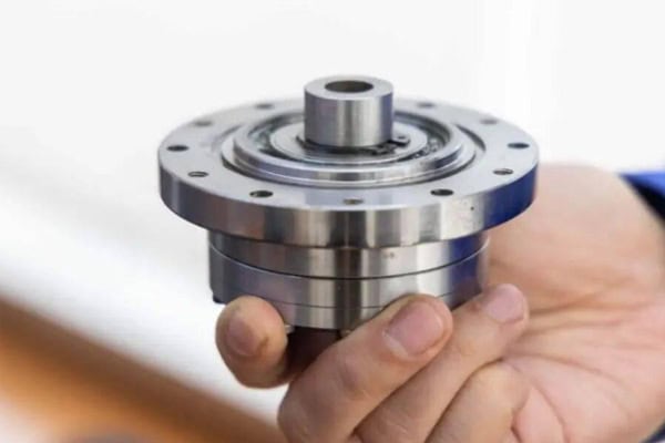
Accuracy control for reducer components needs to cover programming, fixturing, cutting, measurement, and post-processing. Bearing bores, shaft mating surfaces, and flange locating holes are especially important because they directly influence the transmission behavior of robotic joints.
- Establish consistent machining datums: Use stable reference surfaces for critical external diameters, end faces, bearing bores, and mounting surfaces.
- Optimize fixture design: Select appropriate support and clamping positions for thin-wall housings and long shafts to minimize deformation.
- Distribute machining allowances properly: Leave uniform material during roughing and reserve finishing operations for critical dimensions.
- Select appropriate cutting tools: Choose carbide tools, precision boring tools, or high-accuracy turning tools according to material and feature requirements.
- Control cutting vibration: Optimize spindle speed, feed rate, and cutting depth to reduce the influence of vibration on dimensional and surface quality.
- Precision-finish critical bores: Apply precision boring and related finishing processes to improve bearing bore diameter and geometric accuracy.
- Strengthen in-process inspection: Use micrometers, bore gauges, optical measuring equipment, and coordinate measuring machines to verify critical dimensions.
- Implement first-piece and batch inspection: Approve the first completed component before volume machining and perform sampling or full inspection according to production requirements.
Stable process control can reduce dimensional drift and assembly deviations. For high-precision robot reducer components, equipment condition, tool wear, and inspection data should also be managed consistently and remain traceable.
Surface Treatment and Maintenance of Robot Reducer Components
Different reducer components require different surface treatments. Aluminum alloy housings and flanges are commonly treated through anodizing, sandblasting, or coating to improve corrosion resistance and appearance. Steel shafts may undergo heat treatment, plating, or other strengthening processes according to their wear and load requirements. For bearing mating surfaces and sealing areas, the treatment range and coating thickness should be controlled according to engineering specifications so that precision assembly is not affected.
After installation, bearings, seals, and connection flanges should be correctly positioned, and lubrication should be applied according to equipment requirements. During long-term high-frequency robotic operation, operators should monitor the joints for abnormal noise, vibration, temperature rise, or changes in motion accuracy. Loose mounting structures or abnormal wear in mating areas should be addressed promptly. Good machining quality combined with standardized maintenance can help maintain stable reducer transmission performance.
Inspection and Customized Supply Services for Robot Reducer Components
Quality inspection is a critical stage in CNC manufacturing of robot reducer components. Standard dimensions can be checked using calipers, micrometers, bore gauges, and height gauges. Bearing bores, locating holes, flange hole spacing, and complex positional relationships can be verified using optical measuring equipment or coordinate measuring machines. For shaft components, inspection may focus on roundness, radial runout, concentricity, external diameter, and surface roughness.
Customized supply services can cover material procurement, CNC turning, CNC milling, precision boring, tapping, deburring, surface treatment, dimensional inspection, and protective packaging. For robot reducer projects, individual components can be assigned specific inspection standards according to their functions, with critical dimensions receiving additional process control. Prototype projects can use first-piece approval and assembly verification, while volume orders can improve production consistency through standardized CNC programs, tool-life management, and in-process inspection.
From engineering drawing verification to final product delivery, a stable CNC machining process helps robot manufacturers obtain reducer components with consistent dimensions and reliable assembly performance. These components can be used in industrial robotic arms, collaborative robots, SCARA robots, automated equipment, and other high-precision robotic transmission systems.