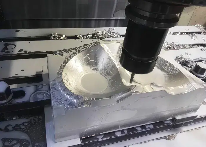
Mill aluminum means using milling machines and cutting tools to remove material from an aluminum workpiece and create the required geometry, dimensions, and surface features. It is one of the most common machining methods for aluminum parts because it offers good precision, flexibility, and efficiency for both simple and complex designs.
In this guide, you will learn what mill aluminum means, why aluminum is well suited for milling, what machines and tools are commonly used, and how the milling process works step by step.
What is Mill Aluminum?
Mill aluminum means machining an aluminum workpiece by using a rotating cutting tool to remove material in a controlled way. It is commonly used to create flat surfaces, pockets, slots, contours, holes, mounting features, and other precision details needed in functional or structural parts.
- Typical Tolerances Of ±0.01 mm To ±0.05 mm
- Common Surface Finish Of Ra 0.8–3.2 μm
- Typical CNC Speed Range Of 8,000–24,000 RPM
- Suitable For 6061, 6063, And 7075 Aluminum
- Works For Prototypes And Medium-Volume Production
- Supports Pockets, Slots, Holes, And Contours
Why Is Aluminum Suitable for Milling?
Aluminum is suitable for milling because it is relatively easy to cut, supports good machining efficiency, and can be used in many industries where weight, appearance, conductivity, or corrosion behavior matter. Its machining advantages make it a common first-choice material for custom CNC parts.
Light Weight and Good Machinability
One of aluminum’s biggest advantages is that it is much lighter than steel while still offering useful mechanical performance. This makes it attractive for products where reducing mass improves function, handling, transport efficiency, or overall design flexibility.
Its machinability is also a major benefit. Many aluminum grades produce good chip formation and can be machined at relatively high speeds. This helps improve productivity, especially in prototype and medium-volume manufacturing.
Good Strength-to-Weight Ratio
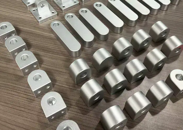
Aluminum is used in many engineered parts because it provides a favorable strength-to-weight ratio. While it does not replace steel in every structural application, it performs very well in many housings, frames, brackets, enclosures, mounting parts, support structures, and lightweight machine components.
For many designers, this balance is what makes aluminum attractive. It is strong enough for many functional uses, but still light enough to help reduce system weight.
Wide Use in Industrial Parts
Aluminum milling is used in a broad range of industrial parts, including:
- Housings
- Brackets
- Base plates
- Machine covers
- Heat sinks
- Structural frames
- Robot components
- Electronics enclosures
- Aerospace fittings
- Automotive support parts
This broad use is one reason why milling aluminum remains a core service in custom CNC machining manufacturing.
What Machines and Tools Are Used to Mill Aluminum?
The machines and tools used to mill aluminum usually include CNC milling machines, high-speed spindles, carbide cutting tools, drilling tools, face mills, and stable fixturing systems. The right machine-tool combination affects both productivity and part quality.
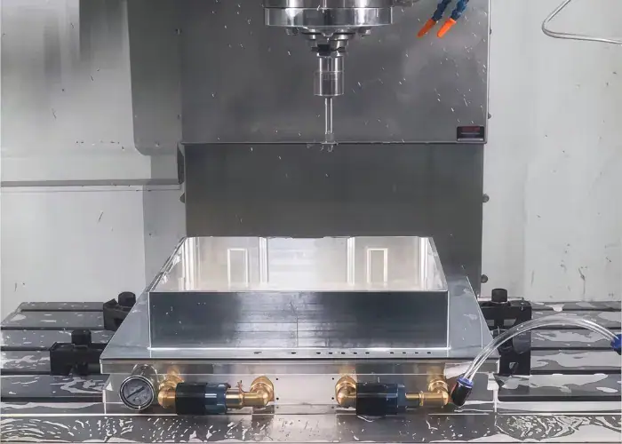
CNC Milling Machines
CNC milling machines are the standard equipment used to mill aluminum in modern manufacturing. They are preferred because they can hold programmed motion accurately and produce repeatable results across prototypes, small batches, and production runs.
Common machine types include:
- 3-axis CNC milling machines
- 4-axis CNC milling machines
- 5-axis CNC milling machines
- Vertical machining centers
- Horizontal machining centers
For simpler aluminum parts, 3-axis machines are often enough. For more complex parts with multi-face features or angled surfaces, 4-axis or 5-axis machining may reduce setups and improve accuracy.
Common Cutting Tools for Aluminum
Cutting tools for aluminum are usually selected for sharpness, chip evacuation ability, and stable cutting performance. Aluminum is not difficult to cut in the same way as hardened steel, but it is sensitive to chip welding and built-up edge, so tool geometry matters.
Tools used for aluminum often feature:
- Sharp cutting edges
- Polished flutes
- Geometry suited to non-ferrous materials
- Carbide construction for better wear resistance
- Coatings when beneficial for chip flow or heat control
A poor tool choice can cause sticking, poor finish, chatter, or burr formation even when the material itself is easy to machine.
Drills, End Mills, and Face Mills
Different tools are designed for different machining tasks, and selecting the right one helps improve accuracy, surface quality, and production efficiency. Among the most commonly used tools for aluminum parts are drills, end mills, and face mills.
- Drillsare used for through holes, pilot holes, and prepared features for tapping or fastening.
- End millsare the most common tools for aluminum milling because they can cut slots, contours, pockets, steps, and general profiles.
- Face millsare used when surfacing larger flat areas efficiently. They are especially useful for preparing stock faces or machining broad reference surfaces.
In many real projects, one aluminum part may use all three categories in a single machining cycle.
Workholding and Fixturing Tools
Workholding is one of the most important parts of aluminum milling because poor clamping can cause movement, distortion, or vibration. Aluminum parts, especially thin-wall or low-rigidity parts, can deform more easily than thick steel blocks if clamping is not properly controlled.
Common workholding methods include:
- Machine vises
- Soft jaws
- Fixture plates
- Vacuum fixtures
- Modular clamps
- Custom jigs for repeated production
Good fixturing improves dimensional consistency, reduces chatter, and helps maintain part stability during roughing and finishing.
How Do You Mill Aluminum Step by Step?
Milling aluminum step by step usually involves planning the part, preparing the raw material, clamping the workpiece, selecting tools, setting cutting parameters, removing material through roughing and finishing, and then inspecting and cleaning the final part. Each step contributes to machining quality.
Part Design and Process Planning
The first step is understanding the part design. Engineers review the drawing or CAD model to identify key features, tolerance requirements, surface finish expectations, wall thickness, hole depths, corner conditions, and machining accessibility.
Good planning reduces risk. It helps determine whether the part should be machined from plate, block, extrusion, or casting, and it also influences tool selection, fixture design, and machining order.
Material Preparation
Material preparation includes selecting the right aluminum alloy and confirming the stock size. The raw material may be cut into blanks before machining begins. At this stage, surface condition, flatness, and stock allowance may also be checked depending on part requirements.
If the wrong grade is used, machining behavior and final part performance can both be affected. That is why material confirmation is part of real production control.
Workpiece Clamping
The workpiece is then clamped in a way that holds it securely while minimizing distortion. This matters because loose clamping can cause part movement, while excessive clamping can bend thinner aluminum features.
The setup must also allow enough tool access. In many parts, fixture design is as important as the toolpath itself.
Tool Selection and Setup
Once the workpiece is secured, the tools are selected according to the feature types and the stage of machining. Larger tools may be used for roughing, while smaller or sharper tools are used for finishing fine details.
Tool setup includes:
- Loading the correct tools
- Checking tool lengths
- Confirming tool diameter offsets
- Making sure tool runout is controlled
Parameter Setting
Cutting parameters are then set based on the aluminum grade, tool type, part geometry, and quality target. These settings include spindle speed, feed rate, axial depth of cut, radial engagement, coolant use, and toolpath strategy.
This step directly affects chip control, heat generation, tool life, cycle time, and final surface finish.
Rough Milling and Finish Milling
Rough milling removes most of the material quickly. The purpose is to shape the part efficiently while leaving enough stock for final finishing. Finish milling then brings the part to final dimensions and improves the surface condition.
A common mistake is trying to finish too aggressively. In aluminum machining, better finish quality usually comes from a stable, lighter, more controlled finishing pass rather than simply increasing cutting force.
Inspection and Cleaning
After machining, the part is inspected and cleaned. Inspection may include dimensional measurement, visual checking, burr review, hole verification, and surface inspection. Cleaning removes chips, coolant residue, and loose debris that could affect later assembly or delivery condition.
What Cutting Parameters Matter When You Mill Aluminum?
The cutting parameters that matter most when milling aluminum are cutting speed, feed rate, depth of cut, and chip evacuation conditions. These factors strongly influence machining efficiency, tool life, burr control, and surface finish.
Cutting Speed
Cutting speed matters because aluminum can usually be machined at higher speeds than many steels, but too much speed without control may still create heat and unstable cutting. The correct value depends on the alloy, cutter diameter, cutter material, machine spindle capability, and whether the cut is roughing or finishing.
Feed Rate
Feed rate affects how the cutter engages the material. If the feed is too low, the tool may rub instead of cut cleanly, increasing heat and built-up edge. If the feed is too high, surface finish may worsen and burr formation may increase.
A stable chip load is generally more important than simply using the highest possible feed.
Depth of Cut
Depth of cut affects both productivity and part stability. Heavier cuts can improve roughing efficiency, but they also raise cutting force and vibration risk. Lighter cuts are often preferred near thin walls, narrow edges, or precision surfaces.
Coolant and Chip Removal
Chip removal is especially important in aluminum milling because chips can cling to the cutter or be recut into the surface. Coolant, mist, or air blast systems help move chips away from the cutting zone and reduce sticking problems.
Good chip evacuation often has a direct effect on:
- Surface quality
- Tool cleanliness
- Edge quality
- Machining stability
How Can You Get Better Results When You Mill Aluminum?
Better results in aluminum milling come from combining the right tools, parameters, fixturing, and process control. Even though aluminum is a machinable material, quality problems can still occur if the setup is not optimized.
Use Sharp Tools for Aluminum
Sharp tools help cut aluminum cleanly instead of smearing it. This reduces burr formation, surface tearing, and heat buildup. Tools designed specifically for aluminum often perform better because their geometry helps the chip release more smoothly.
Reduce Built-Up Edge
Built-up edge is one of the most common issues when machining aluminum. It happens when material adheres to the cutting edge and changes how the tool cuts.
Ways to reduce built-up edge include:
- Using sharper tools
- Improving coolant or lubrication
- Adjusting speed and feed balance
- Improving chip evacuation
- Replacing worn cutters in time
Prevent Part Deformation
Thin aluminum parts can deform during machining because of clamping force, internal stress, or cutting load. Better process planning often helps reduce this problem.
Common approaches include:
- Using balanced clamping
- Machining both sides in a planned sequence
- Leaving proper stock for finishing
- uUsing lighter finishing passes
- Reducing force near thin features
Improve Surface Finish
Surface finish matters for visible parts, sealing faces, sliding contacts, and mating assemblies. Better finish usually comes from stable workholding, good tool condition, refined finishing passes, and proper chip control.
Control Vibration and Chatter
Chatter is a common problem in aluminum milling when the setup lacks rigidity or the tool extends too far. It can leave visible marks, reduce tool life, and hurt accuracy.
It is often improved by:
- Shortening tool overhang
- Improving clamping rigidity
- Adjusting spindle speed
- Refining step-over and depth values
- Improving machine setup stability
What Problems Commonly Happen When You Mill Aluminum?
The most common problems when milling aluminum are material sticking to the tool, poor surface roughness, burrs, chatter marks, and dimensional inaccuracy. These are not unusual problems. They are part of real machining control and should be managed by process planning.
Aluminum Sticking to the Tool
Aluminum sticking to the tool is common because aluminum can adhere to the cutting edge under heat and friction. When this happens, cutting becomes unstable and the machined surface can deteriorate quickly.
Poor Surface Roughness
Poor roughness may come from dull tools, tool vibration, unstable feed, poor coolant delivery, or recutting chips. It often becomes more visible on cosmetic parts or flat exposed surfaces.
Burr Formation
Burrs are common on aluminum edges, hole exits, and thin features. They may seem small, but they can affect assembly, safety, and part appearance. Burr control is often part of the finishing plan.
Chatter Marks
Chatter marks indicate instability in the cut. These marks usually appear as repeated patterns or waviness on the machined surface. They are common when the setup lacks stiffness or when tool engagement is not well balanced.
Dimensional Inaccuracy
Dimensional errors may come from fixture movement, tool deflection, thermal changes, machine calibration issues, or wrong tool offsets. In precision aluminum parts, these factors matter because even small deviations can affect fit and function.
What Aluminum Grades Are Commonly Used in Milling?
The aluminum grades most commonly used in milling include 6061, 6063, and 7075. Each grade offers a different balance of machinability, strength, appearance, and application suitability.
6061 Aluminum
6061 is one of the most common general-purpose aluminum alloys used in CNC machining. It offers good machinability, useful strength, broad availability, and reliable performance in many structural and industrial parts.
It is often used for:
- Brackets
- Housings
- Base plates
- Frames
- Machine components
6063 Aluminum
6063 is commonly used in CNC machining when appearance, surface smoothness, and good corrosion resistance are important. It is often associated with extrusions and is suitable for lighter structural and decorative applications, while also being practical for custom machined components.
It is often used for:
- Enclosures
- Frames
- Cover panels
- Architectural components
- Light structural parts
7075 Aluminum
7075 is widely used in CNC machining when higher strength and better mechanical performance are required. It is often selected for aerospace, high-load, and weight-sensitive applications. Although it is generally more expensive than 6061, it provides excellent strength for demanding parts.
It is often used for:
- Aerospace fittings
- Robot components
- Structural frames
- High-load brackets
- Precision mechanical parts
How Material Grade Affects Milling Performance
Material grade affects machining performance through:
- Strength level
- Chip behavior
- Burr tendency
- Surface response
- Cutting force
- End-use suitability
That is why alloy choice should not be based on machinability alone. It should also match the part’s actual performance requirements.
When Should You Mill Aluminum Instead of Using Other Processes?
You should mill aluminum when the part needs geometric flexibility, tighter machining control, rapid design changes, or custom features that are not efficient to produce by forming-only processes. Milling is especially useful for prototypes, development parts, and low- to medium-volume production.
Compared with Turning
Turning is best for rotational parts such as shafts, bushings, and rings. Milling is the better choice when the part has flat faces, slots, pockets, complex outer contours, or multi-face features.
Compared with Stamping
Stamping is better for high-volume sheet metal parts with stable geometry and dedicated tooling. Milling is more suitable when the part is thicker, more structural, more customized, or still in development.
Compared with Casting
Casting is useful when near-net-shape production and volume efficiency are important, but milling is usually better for tighter tolerances, more precise features, and faster design changes.
Compared with Extrusion Plus Secondary Machining
Extrusion works well for long parts with constant cross-sections, but many extruded aluminum parts still require milling afterward for holes, end features, slots, mounting details, or local precision surfaces.
FAQs
What Is The Best Aluminum Grade For CNC Milling?
6061-T6 is the most common aluminum grade for CNC milling because it offers good machinability, strength, and corrosion resistance. Its tensile strength is about 290 MPa. For higher-strength parts, 7075-T6 is often used, with strength around 510 MPa.
How Do You Prevent Aluminum From Sticking To Cutting Tools?
Aluminum sticking can be reduced by using sharp carbide tools, polished flutes, and proper coolant. Tools with 2 or 3 flutes usually improve chip evacuation. Correct chip load and stable cutting conditions also help prevent built-up edge.
What Spindle Speeds And Feed Rates Are Suitable For Milling Aluminum?
Aluminum is usually milled at higher speeds than steel. For carbide tools, cutting speeds often range from 300 to 1,000 m/min. A 6 mm end mill may run at 12,000 to 18,000 RPM with feed rates around 1,000 to 3,000 mm/min.
What Surface Finish Can You Achieve When Milling Aluminum?
Standard CNC milling on aluminum often produces a surface finish around Ra 1.6 to 3.2 µm. With finishing passes and stable machining conditions, the surface can improve to about Ra 0.8 to 1.6 µm.
Can Milled Aluminum Parts Be Anodized After Machining?
Yes, milled aluminum parts can be anodized after machining. Alloys such as 6061 are commonly used because they respond well to anodizing. Standard anodized layers are usually 5 to 25 µm thick, depending on the application.
Conclusion
Mill aluminum matters because it gives manufacturers a practical way to produce lightweight, accurate, and versatile parts across a wide range of industries. When tool selection, cutting parameters, fixturing, chip control, and finishing strategy are managed well, aluminum milling can deliver strong dimensional consistency, good surface quality, and efficient production performance.
At TiRapid, we support manufacturers with precision CNC machining for custom aluminum parts across prototyping and production programs. Upload your drawing to discuss your machining requirements and get a tailored solution for your next project.