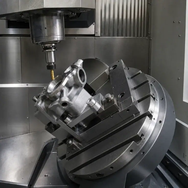
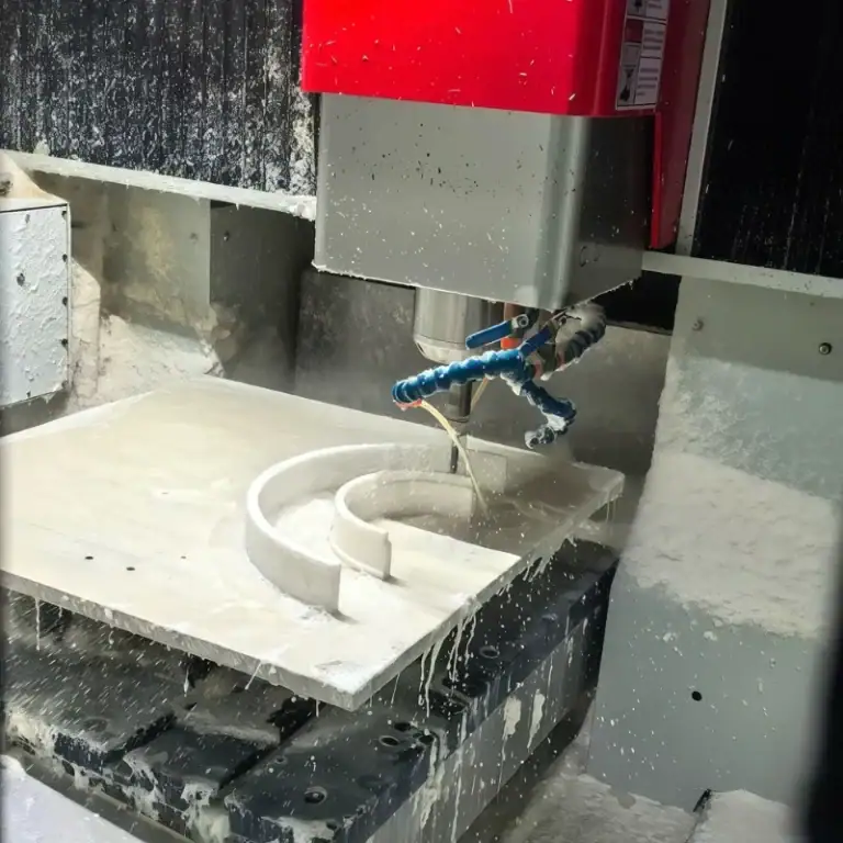
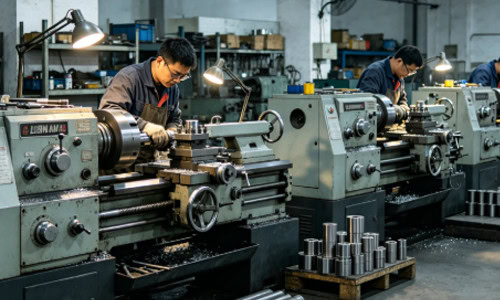
Burr formation is one of the most common problems during turning operations. Whether machining steel, stainless steel, aluminum, or copper parts, edges may develop burrs, metal flanging, or surface tearing after machining. Burrs not only affect product appearance but may also reduce assembly precision and even impact sealing performance and service life. In precision components and batch production, burr problems become even more noticeable. If burrs are not controlled in time, they will increase deburring costs and reduce overall production efficiency.
Why Burrs Easily Occur During Turning
Burr formation is usually related to material plasticity, tool condition, and cutting method. When material cannot fully separate during cutting, residual metal tends to remain at the edge of the workpiece.
Materials with High Plasticity Easily Form Burrs
Some materials have strong ductility and do not fracture cleanly during machining.
Common materials include:
- Stainless steel
- Copper parts
- Aluminum alloys
- Low-carbon steel
The softer the material, the more obvious the edge stretching effect becomes.
Extrusion Occurs During Cutting
If the cutting tool is not sharp enough, the process may shift from cutting to extrusion.
This may lead to:
- Edge flanging on the workpiece
- Surface tearing
- Small metal residue
- Uneven edges
This situation is more common during finishing operations.
Tool Problems Can Increase Surface Burrs
Tool condition directly affects cutting performance. If the tool is severely worn or the tool geometry is improper, burr problems usually become much more serious. During machining, sharper tools create cleaner chip separation and produce smoother workpiece edges.
Severe Tool Wear
After the cutting tool becomes worn, the cutting edge gradually becomes dull and cutting resistance increases significantly.
Common situations include:
- Rough workpiece edges
- Increased burr length
- Surface tearing marks
- Reduced machining accuracy
The effect becomes more obvious during continuous machining.
Improper Tool Geometry
Tool rake angle, clearance angle, and nose radius all influence burr formation.
For example:
- Small rake angle increases friction
- Insufficient clearance angle causes extrusion
- Excessive nose radius creates edge flanging
- Dull cutting edges cause surface tearing
Proper tool geometry helps improve cutting conditions.
Incorrect Tool Material Selection
Different materials require different cutting tools.
For example:
- Stainless steel requires high-toughness tools
- Aluminum parts require highly sharp tools
- Copper parts require reduced built-up edge
- High-hardness materials require wear-resistant tools
Improper tool selection increases the likelihood of burr formation.
Improper Cutting Parameters Also Cause Burrs
Cutting parameters directly affect chip breaking conditions. If parameter settings are unsuitable, residual metal is more likely to remain along workpiece edges.
Unstable Cutting Speed
When cutting speed is too low, the material is more likely to deform plastically.
This may lead to:
- Surface burrs
- Edge flanging
- Interrupted cutting
- Rough surface finish
Different materials require suitable speed ranges.
Improper Feed Rate Setting
If feed rate is too low, the tool may rub against the workpiece surface for too long.
This may cause:
- Material stretching
- Surface tearing
- Increased burr formation
- Uneven workpiece edges
Excessive feed rate, however, may increase cutting impact.
Cutting Depth Too Shallow
If cutting depth is too small, some areas may enter a friction-based machining state.
This may result in:
- Residual metal
- Edge deformation
- Uneven surface quality
- Increased burr formation
Finishing operations require proper allowance control.
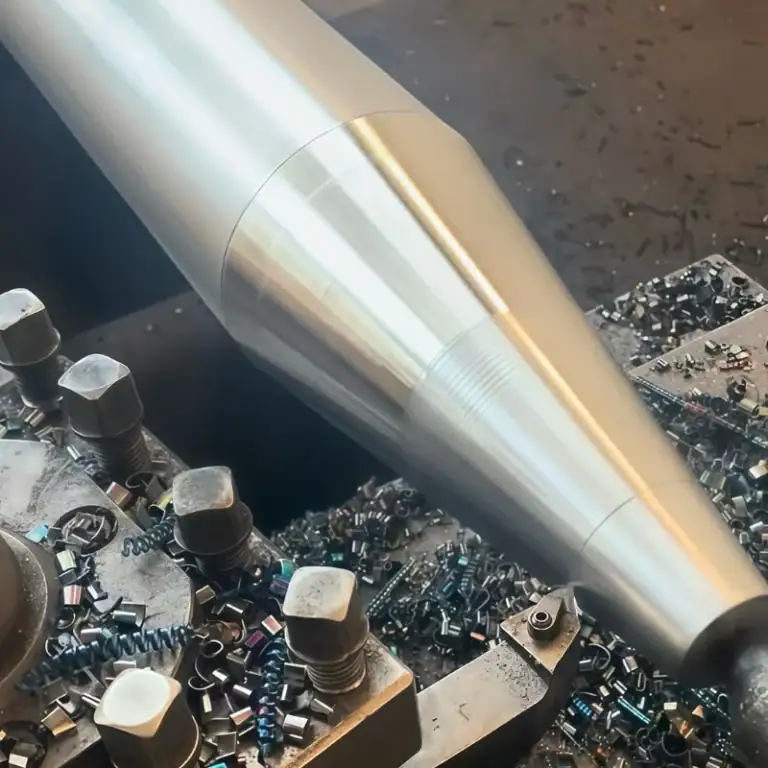
Cooling and Chip Evacuation Also Affect Burr Formation
Many burr problems are not caused only by tooling but are also related to cooling and chip evacuation conditions. If chips cannot be removed in time, they may repeatedly rub against the workpiece surface, causing burrs and scratches.
Insufficient Cooling Causes Built-Up Edge
During machining, if cooling performance is poor, material may stick to the cutting tool surface.
This may result in:
- Built-up edge formation
- Surface tearing
- Poor cutting smoothness
- Increased edge burrs
Copper parts and stainless steel are more likely to experience these issues.
Chips Wrapping Around the Workpiece
Long chips that continuously wrap around the workpiece may repeatedly scratch the machined surface.
Possible problems include:
- Surface scratches
- Edge burrs
- Rough surface finish
- Failed finishing operations
Proper chip evacuation is therefore essential during machining.
How to Reduce Burrs on Turning Surfaces
Although burr formation cannot always be completely avoided, process optimization can significantly reduce burr generation. During machining, cutting tools should remain sharp, while cutting speed and feed rate should be adjusted according to material characteristics. For highly ductile materials, cooling and chip evacuation conditions require special attention to prevent chips from continuously rubbing against the workpiece surface.
Keep the Cutting Tool Sharp
Sharp tools improve chip separation performance.
This helps reduce:
- Edge flanging
- Surface tearing
- Residual metal
- Workpiece burrs
Regular tool replacement helps maintain stable machining quality.
Optimize Cutting Parameters
Proper parameters improve cutting conditions.
Common methods include:
- Improving cutting continuity
- Maintaining stable feed rate
- Avoiding excessively shallow cutting
- Reducing friction-based machining
Stable cutting conditions help reduce burr formation.
Improve Cooling and Chip Evacuation
Once cooling and chip evacuation become stable, workpiece surface quality improves significantly.
For example:
- Increase coolant flow rate
- Adjust coolant spray direction
- Use chip breaker tools
- Ensure timely chip evacuation
These methods help reduce repeated chip friction.
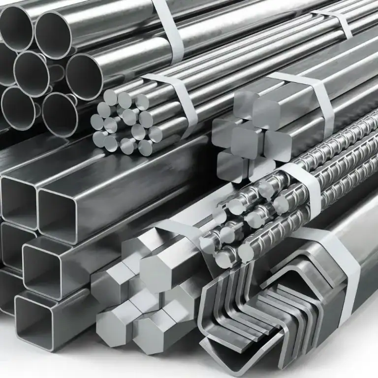
Differences in Burr Formation Between Materials
Different materials show different burr characteristics during turning. Stainless steel and copper parts are more likely to develop stretched burrs because of their high ductility. Aluminum parts machine easily, but dull tools may still cause edge flanging. Certain high-hardness materials may produce small edge chipping instead. During machining, cutting tools and parameters should be selected according to material characteristics.
For high-precision parts, burrs not only affect appearance but may also influence dimensional accuracy and assembly quality. Therefore, workpiece edge conditions should be monitored continuously during machining, and tooling and machining conditions should be adjusted in time to maintain stable machining quality.