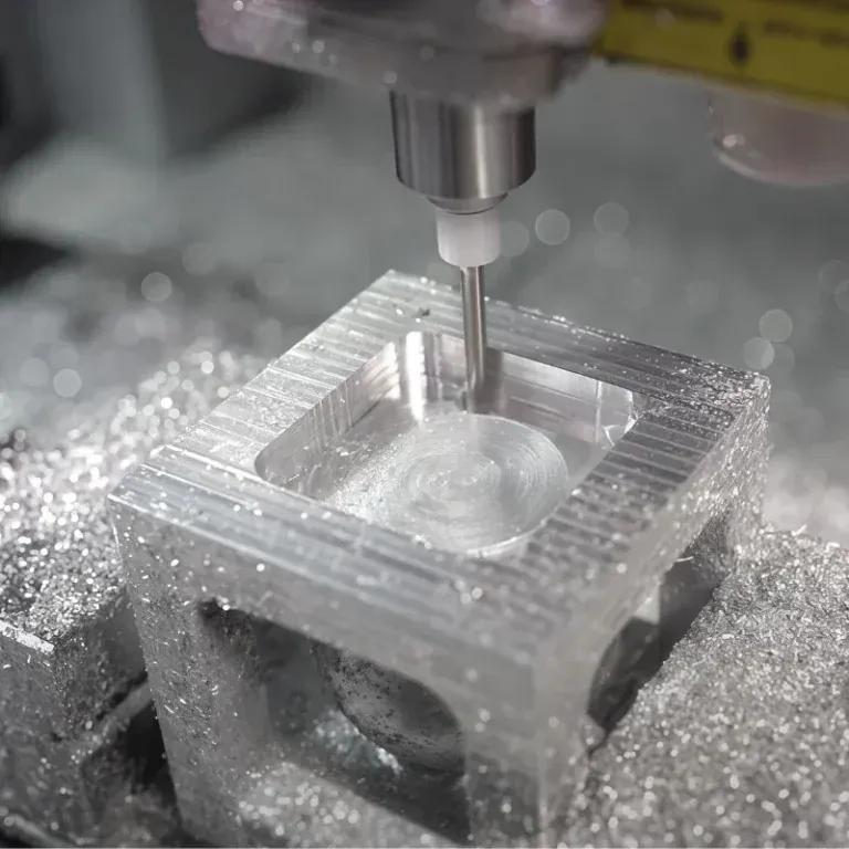
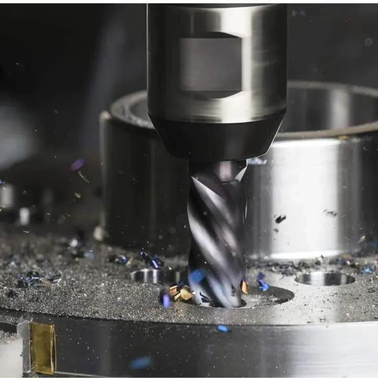
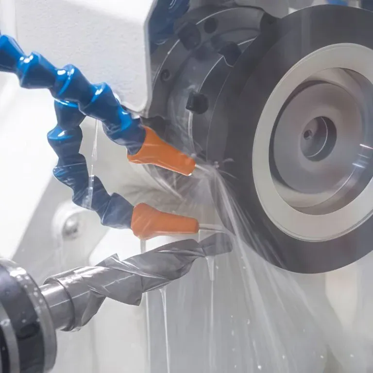
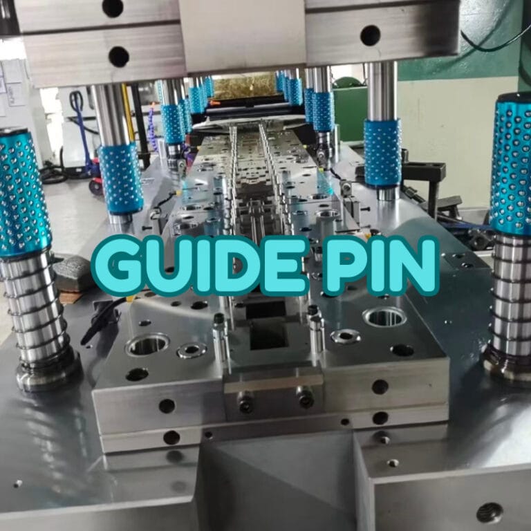
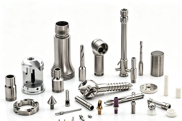
Endoscopic instruments usually need to perform observation, positioning, grasping, cutting, conveying, and other actions within a relatively small space. Therefore, the dimensions, mating relationships, and surface conditions of internal components need to remain stable. Compared with general mechanical parts, surgical parts for endoscopic instruments often feature small dimensions, fine structures, multiple holes, and relatively thin wall thicknesses. Some parts also need to be assembled with lenses, catheters, gripping components, or other precision components. CNC machining can perform precise cutting of metals or engineering plastics according to 3D drawings and engineering requirements, and complete the production of customized parts through turning, milling, drilling, tapping, micro-machining, and other processes.
What Are the Machining Characteristics of Endoscopic Surgical Parts?
The internal space of endoscopic instruments is limited, so components generally need to be made smaller while maintaining sufficient strength and stability. A small component may contain holes, grooves, threads, steps, and mating surfaces at the same time. Therefore, the machining sequence needs to be arranged in advance to reduce dimensional variations caused by repeated clamping.
Stable Machining of Small-Dimensional Structures
Common structures of endoscopic surgical parts include connectors, sleeves, positioning components, gripping components, lens mounting structures, guide components, and various non-standard small metal parts. Some components have a small outer diameter while still requiring internal holes or steps. It can be difficult for conventional machining methods to balance dimensional accuracy and surface quality. CNC turning is suitable for shaft-type, sleeve-type, and cylindrical parts, and can continuously complete structures such as external diameters, internal holes, end faces, grooves, and threads. For parts with flat surfaces, irregular contours, and multi-directional holes, CNC milling or multi-axis machining can be combined to complete the process.
Controlling Machining Forces for Thin Walls, Fine Grooves, and Micro-Holes
Some endoscopic components use thinner wall thicknesses to reduce overall size. If the cutting force is too high during machining, the component may experience slight deformation, which can eventually affect assembly. Therefore, a suitable clamping method and machining sequence need to be selected according to the component structure before production. For example, the main positioning surfaces can be machined first, followed by fine structures; for thin-wall areas, the cutting amount per pass can be reduced, with dimensional re-inspection performed during subsequent processes. For fine grooves, micro-holes, and other features, appropriately sized small tools should also be used while controlling cutting conditions.
Assembly Dimensions
Endoscopic surgical parts are rarely used independently. One sleeve needs to connect with another component, one positioning component needs to accurately enter its installation position, and one gripping structure needs to maintain smooth movement. Therefore, hole diameters, shaft diameters, clearances, coaxial relationships, and positional dimensions shown on the drawings may all affect final assembly. Identifying these critical dimensions before machining can make the production process more stable.
How to Develop a CNC Machining Solution for Endoscopic Parts
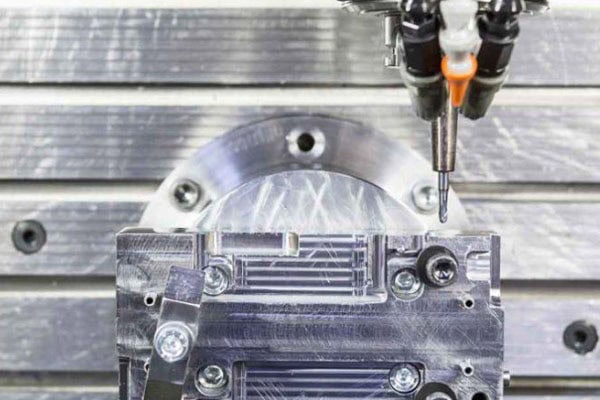
Engineers need to first confirm the structural characteristics, material, tolerances, surface treatment, and assembly requirements of the part, and then determine whether turning, milling, drilling, tapping, or multi-axis machining is appropriate. Endoscopic components are usually relatively compact in structure. If the machining sequence is not properly arranged, it may increase tool usage, the number of clamping operations, and subsequent finishing work. It may also cause deformation in thin-wall areas, hole position deviations, or unstable surface quality. Therefore, developing a reasonable machining route in advance can help improve production efficiency, reduce rework, and ensure that the parts meet subsequent assembly and application requirements.
Confirm Drawings and Critical Dimensions
After receiving 3D files such as STEP, STP, and IGES, as well as engineering drawings such as PDF, DWG, and DXF, the structure, material, dimensions, tolerances, surface requirements, and special markings of the part can be checked first. Particular attention should be given to assembly positions and critical dimensions. For general external dimensions, production can proceed according to the drawings; for holes, grooves, threads, and positioning surfaces that affect assembly, these should be separately marked in the production plan, with corresponding inspection methods arranged.
Select the Machining Method According to the Structure
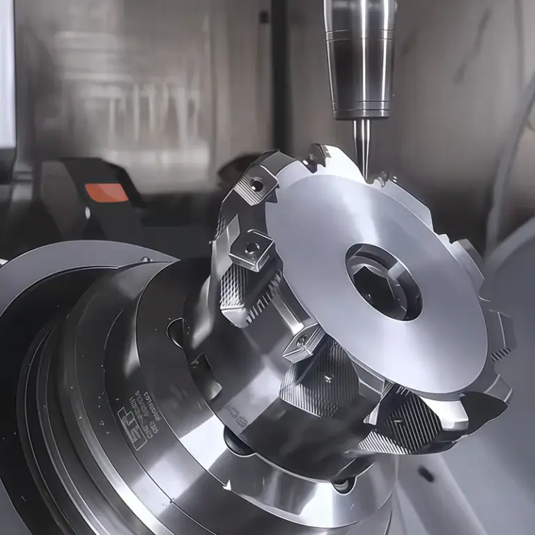
Different parts are suitable for different machining equipment. Cylindrical parts can generally be considered for CNC turning first; parts with complex flat surfaces and spatial contours can be machined using CNC milling; if the structure contains complex features in multiple directions, 5-axis CNC machining can be used to reduce the number of clamping operations. The TiRapid website provides CNC milling, CNC turning, 5-axis CNC machining, and micro-machining services, allowing the machining process to be selected according to the part structure.
| Common Machining Methods for Part Structures and Key Controls | ||
| Sleeves, shaft parts | CNC Turning | Outer diameter, inner hole, concentricity |
| Small housings | CNC Milling | Hole positions, flat surfaces, wall thickness |
| Irregular connectors | 3-axis/5-axis milling | Contour, positional dimensions |
| Fine groove and hole parts | Micro CNC machining | Groove width, hole diameter, burrs |
| Threaded connection parts | Turning/Milling/Tapping | Thread dimensions, mating performance |
Integrate Inspection into the Machining Process
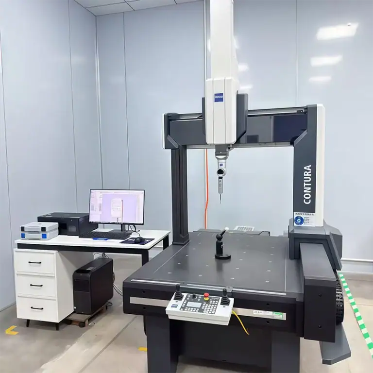
Endoscopic components are not suitable for inspection only after all machining has been completed. Critical dimensions can be checked during the semi-finished stage to identify dimensional deviations in time and avoid material and time waste caused by continuing the machining process. Common inspections can include dimensional measurement, hole diameter inspection, thread inspection, visual inspection, and CMM inspection. The TiRapid website describes its CMM inspection capabilities and their use in quality control for precision CNC parts. For projects with higher requirements, corresponding dimensional inspection records can also be provided according to customer drawings, making it easier for engineering and procurement teams to confirm whether the parts meet drawing requirements.
How to Select Materials and Surface Treatments for Endoscopic Surgical Parts
Material selection directly affects machining difficulty, component strength, corrosion resistance, and subsequent processing methods. Actual material selection needs to be determined based on the component’s application, contact environment, assembly requirements, and engineering specifications provided by the customer. Selection should not be based solely on price. For endoscopic surgical parts, material biocompatibility, high-temperature resistance, cleaning and sterilization resistance, and dimensional stability during long-term use should also be considered. Different materials have different requirements for cutting speed, tool wear, surface roughness, and deformation control, so they need to be evaluated in advance during the design stage. Proper material selection can not only improve machining efficiency but also reduce problems during subsequent assembly, surface treatment, and quality inspection.
Stainless Steel Is Suitable for Precision Structural Parts
Stainless steels such as 316L are commonly used for medical device components and provide good corrosion resistance and mechanical properties. Stainless steel can be considered for sleeves, connectors, gripping components, structural supports, and other parts according to the specific design. However, stainless steel generally has higher hardness and greater machining difficulty than ordinary aluminum. Tool wear, cutting heat, and machining deformation therefore need to be controlled during processing.
Titanium Alloys and Engineering Plastics for Special Structures
Titanium alloys offer high strength and relatively low weight and have application value in certain medical device structures. Engineering plastics such as PEEK provide properties including heat resistance and resistance to chemical media and can be used for specific insulating, supporting, or structural components. It should be noted that the material name alone does not indicate that a component can be used clinically. The final material grade, surface treatment, cleaning requirements, and application environment should be confirmed according to the design and regulatory requirements of the medical device product.
Surface Quality Needs to Be Determined According to the Application
After machining, components may require deburring, polishing, passivation, electropolishing, or other specified treatments. For endoscopic surgical parts, residual burrs on edges may affect assembly and use, so the removal of sharp edges generally needs to be included in the machining requirements. Surface treatment can also affect dimensions. If the dimensions of a hole or mating surface change after post-processing, the assembly clearance may also change. Therefore, surface treatment requirements need to be confirmed before production, and related dimensional changes should be included in dimensional control.
TiRapid Custom Endoscopic Parts Production Process
The customized production of endoscopic surgical parts can begin with an engineering file and then proceed through process evaluation, prototype machining, inspection, and batch manufacturing. The engineering team first analyzes the 3D model, 2D drawings, material, tolerances, and surface treatment requirements to determine whether the part is suitable for machining and identify potential problems caused by thin walls, deep holes, fine grooves, or complex assembly structures. Prototype machining is then performed to verify dimensions, appearance, and assembly performance. Based on inspection results, machining parameters can be optimized before entering small-batch or batch production. This process can reduce the risk of rework and allow customers to confirm component performance and application results before formal mass production.
Drawing Evaluation and DFM Recommendations
After customers submit CAD files and engineering drawings, TiRapid can perform DFM checks according to the part structure, including hole positions, wall thickness, tool accessibility, machining sequence, and material selection. If a certain feature may increase machining difficulty, modification suggestions can be provided before production instead of waiting until machining has been completed. For medical device projects requiring rapid development, this early communication can reduce repeated prototyping.
Prototype Machining and Dimensional Verification
After the process is confirmed, the project enters the prototype machining stage. The purpose of prototypes is not only to verify appearance but also to check assembly, movement, dimensions, and design performance. For example, after a connector for an endoscopic gripping assembly is machined, it needs to be assembled with the corresponding structure to confirm whether the hole positions are accurate, whether the threads operate smoothly, and whether interference exists between moving components. After prototype approval, production parameters can be adjusted according to actual feedback.
Small-Batch Production and Quality Control
After the prototypes pass inspection, small-batch production can be arranged according to project requirements. The key objective during the small-batch stage is to maintain dimensional consistency for every component rather than simply increasing machining speed. For parts from the same batch, sampling inspection or 100% inspection can be performed according to drawing requirements, with particular attention to hole diameters, outer diameters, threads, critical positioning dimensions, and surface conditions. For structurally complex components, equipment such as CMM can also be used to assist dimensional verification.
Packaging and Subsequent Manufacturing Support
Precision small parts can be susceptible to impact, scratches, or mixing during transportation, so packaging also needs to be included in the production plan. After inspection, parts can be classified and packaged according to part numbers, quantities, and customer requirements. TiRapid provides not only CNC machining but also sheet metal fabrication and 3D printing services, supporting production from prototypes and small batches to scaled manufacturing. The website also describes value-added services including CAD file support, assembly, procurement, and packaging design, which can reduce repeated communication between customers and different suppliers.
Frequently Asked Questions
Can Endoscopic Surgical Parts Be Machined in Small Quantities?
Yes. For new product development, single-piece or small-batch prototype machining can be performed first to verify dimensions and assembly performance before proceeding to subsequent batch production. This can reduce large investments before the design has been fully confirmed.
Can CNC Machining Handle Very Small Endoscopic Parts?
The specific drawing can be evaluated to determine feasibility. Part dimensions, hole diameter, groove width, wall thickness, material, and tolerances can all affect the machining method. For relatively small components, an engineering evaluation is required before quotation to determine suitable tools, equipment, and machining solutions.
What Information Is Usually Required for Endoscopic Parts?
It is generally recommended to provide 3D files such as STEP and STP, together with engineering drawings containing dimensional and tolerance requirements. If there are also material certificates, surface treatment requirements, inspection reports, or packaging requirements, they can be provided together. More complete information generally allows for more accurate engineering evaluation and quotation.
Can Prototypes Be Made Before Batch Machining?
Yes. Prototype verification is a common production method during the development of medical device components. Prototypes can help identify dimensional, assembly, or structural issues in advance before moving to small-batch production, helping reduce rework after batch machining.
The advantage of CNC machining is that non-standard parts can be manufactured according to specific drawings, without requiring customers to change their designs to accommodate existing products. For products that are still in the early development stage, a small number of prototypes can be produced first to confirm that the components can be installed correctly before increasing the quantity. For projects that have already entered production, small-batch or batch machining can be arranged according to actual requirements. If you already have STEP, STP, PDF, or other engineering files for endoscopic components, you can send them directly to TiRapid. Engineers can first review the part structure and machining requirements and then provide suitable production recommendations and a quotation. This makes the process from drawings to finished products clearer and also makes it easier to identify potential machining issues in advance. For endoscopic instrument projects requiring precision CNC parts, choosing a manufacturer capable of handling engineering communication, machining, inspection, and subsequent delivery can reduce intermediate steps and make project execution more efficient.
Email: projects@tirapid.com
Phone: +86 760 8999 8536