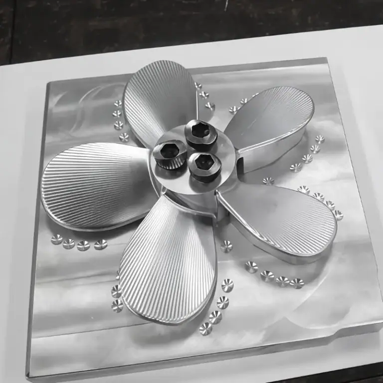
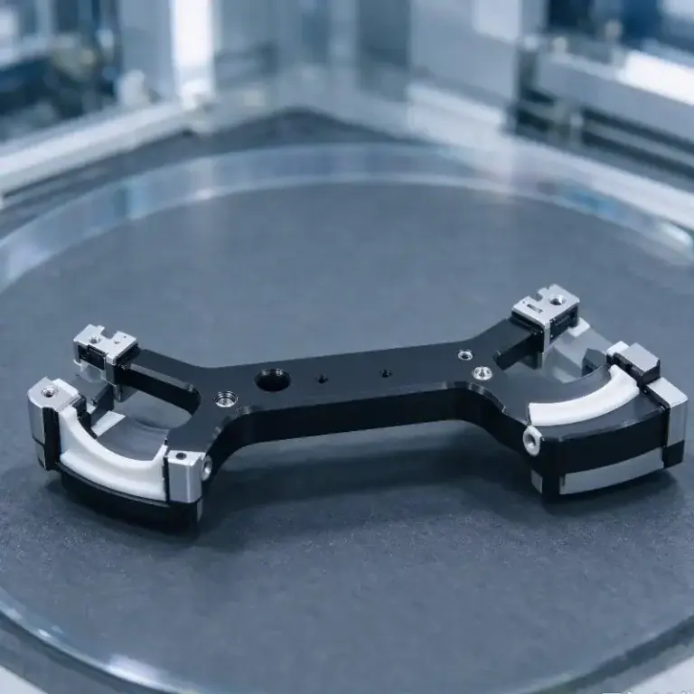
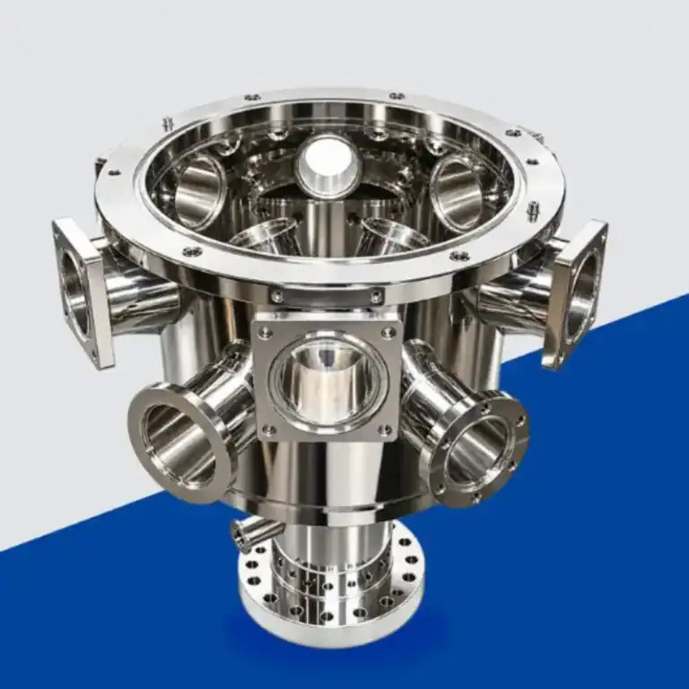
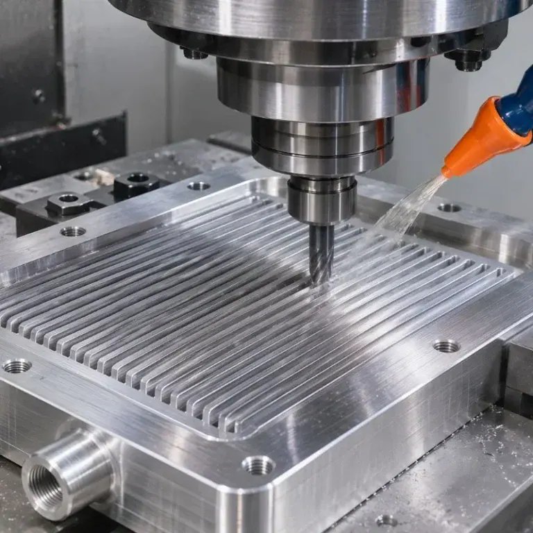
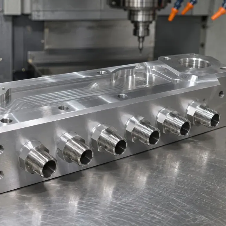
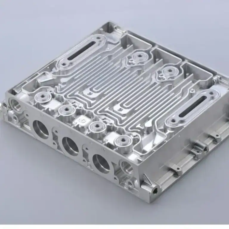
Oil and gas equipment often operates under high pressure, vibration, corrosive conditions, and significant temperature changes. As equipment designs become more advanced, their structural components also become increasingly complex. Irregular housings, precision brackets, multi-hole connectors, equipment mounting bases, and integrated load-bearing structures often feature irregular profiles, deep cavities, intersecting holes, thin walls, and multi-angle machining surfaces. Conventional machining methods may struggle to meet dimensional accuracy, structural strength, and assembly requirements simultaneously. CNC precision machining uses multi-axis machining, custom fixtures, and digital programming to manufacture complex structural components with consistent quality, supporting oil drilling, oilfield monitoring, pipeline systems, and energy processing equipment.
Key Advantages of CNC Machining for Complex Oilfield Structural Parts
Complex structural parts in oilfield equipment perform important functions such as mounting, connecting, supporting, sealing, protecting, and transferring loads. Their structural design directly affects equipment assembly and long-term operating stability. CNC machining allows manufacturers to develop machining strategies based on 3D models and engineering drawings. It reduces positioning errors caused by repeated setups while improving consistency when machining complex profiles and precision features.
Multi-Axis Machining Improves Complex Structural Manufacturing
Complex structural parts often contain angled holes, curved surfaces, deep cavities, irregular grooves, and mounting holes in different directions. When machining these features with conventional three-axis equipment, multiple workpiece repositioning operations may be necessary, increasing setup time and machining errors. Five-axis CNC machining allows the tool and workpiece to move in multiple directions, making it possible to machine several surfaces in one setup. This is particularly suitable for oilfield components with complicated spatial features.
The main advantages of multi-axis machining include:
- Fewer Repeated Setups: Multiple machining areas can be completed in one or fewer setups, reducing errors caused by changing positioning references.
- Improved Complex Surface Machining: The relative position between the tool and workpiece can be adjusted to provide better access to irregular surfaces and angled machining areas.
- Higher Hole Position Accuracy: Mounting holes, positioning holes, and connection holes in different directions can be programmed using consistent coordinate references.
- Reduced Machining Time: Fewer workpiece transfers, repositioning operations, and auxiliary processes help improve manufacturing efficiency.
For compact oil and gas equipment components with numerous machining features, multi-axis CNC machining provides greater manufacturing flexibility. The actual machine configuration should still be selected according to component dimensions, material properties, and tolerance requirements to avoid unnecessary costs.
Customized Structural Machining Improves Equipment Compatibility
Oilfield equipment is often designed according to site conditions, equipment models, and operating requirements. Mounting interfaces, support positions, and available installation space can vary between systems. Standard components may not fully satisfy these requirements. CNC machining enables custom manufacturing based on customer-provided CAD drawings or 3D models, allowing manufacturers to adjust hole diameters, groove widths, wall thicknesses, connection positions, and external profiles.
For components that must work with sensors, control modules, pipelines, or other mechanical assemblies, potential interference and assembly clearances can also be evaluated before machining. Customized manufacturing improves compatibility between individual components and complete equipment systems while reducing on-site modification work.
Multiple Machinable Materials Support Different Operating Conditions
Material selection for complex oilfield structural parts must consider mechanical loads, corrosion exposure, temperature variations, weight, and manufacturing costs. Common materials include stainless steel, alloy steel, aluminum alloys, and selected corrosion-resistant nickel-based alloys. CNC machining can accommodate different material properties by adjusting cutting tools, cutting speeds, feed rates, and cooling methods.
For load-bearing structures, alloy steel with suitable strength and toughness may be considered. Aluminum alloys can be evaluated for instrument brackets and auxiliary housings where weight reduction is important. Components exposed to corrosive media require materials selected according to the chemical composition of the media, operating temperature, and service environment. Material grades, heat treatment conditions, and actual operating requirements should be confirmed before production.
Machining Methods and Applications of Complex Oilfield Structural Parts
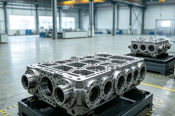
Manufacturing complex structural components requires coordinated planning, from drawing evaluation and material preparation to process development and final inspection. Different components have different structural characteristics. Deep cavities, thin walls, intersecting holes, and complicated connection surfaces require suitable tool paths and workholding methods. A well-planned machining sequence helps reduce material deformation, improve process stability, and ensure that finished components meet equipment assembly requirements.
CNC Machining Processes and Manufacturing Workflow
Oilfield components typically undergo rough machining, semi-finishing, finishing, and inspection. For irregular components or workpieces requiring substantial material removal, the machining sequence must be carefully arranged to prevent localized stress concentration and thin-wall deformation.
Common manufacturing processes include:
- Drawing and Model Evaluation: Review 3D models, dimensional tolerances, geometric tolerances, hole relationships, and assembly references. Identify deep cavities, thin walls, and areas with limited tool access.
- Material Cutting and Blank Preparation: Select suitable blanks according to component geometry and material specifications. Reserve appropriate machining allowances and verify material documentation.
- CNC Rough Machining: Remove major material allowances and establish key reference surfaces, prioritizing stable positioning and load-bearing areas.
- Semi-Finishing: Gradually machine complex profiles, internal cavities, mounting grooves, and connection structures while retaining sufficient material for final finishing.
- Multi-Axis Finish Machining: Use suitable tools and machining paths to complete curved surfaces, angled holes, precision interfaces, and critical mating features.
- Deburring and Surface Treatment: Remove burrs from hole openings, intersecting holes, and component edges. Apply surface treatments according to engineering requirements.
- Dimensional Inspection and Delivery: Check critical dimensions, hole positions, flatness, and geometric tolerances. Provide inspection records according to project specifications and applicable standards.
For thin-wall components, staged material removal, optimized clamping positions, and controlled cutting loads can help reduce deformation risks. Deep-cavity machining requires careful attention to tool overhang, chip evacuation, and machining vibration to prevent tool deflection from affecting dimensional accuracy.
A clearly defined manufacturing workflow makes complex component production more controllable. For parts with unusual structures or demanding tolerances, trial machining should be completed before batch production to verify process stability.
Machining Applications for Irregular Housings and Equipment Mounting Bases
Irregular housings and mounting bases are commonly used in oilfield control equipment, monitoring systems, auxiliary wellsite devices, and energy processing equipment. These components often need to meet requirements for external mounting dimensions, internal space arrangements, connection hole positions, and equipment protection.
CNC machining can produce irregular external profiles, positioning steps, threaded holes, cable channels, and equipment mounting interfaces. This helps maintain proper assembly relationships between housings and internal components. For large or structurally complex bases, particular attention should be paid to mounting surfaces, support positions, and the positional accuracy of hole patterns to prevent misalignment or uneven loading after assembly.
If a component serves as part of a pressure boundary, it must undergo the pressure, leakage, and other inspections specified by its design. Dimensional compliance alone is not sufficient to establish pressure-bearing safety.
Machining Applications for Multi-Hole Connectors and Equipment Supports
Multi-hole connectors, instrument mounting plates, and mechanical support components in oilfield equipment are commonly used to connect different modules or withstand loads generated during equipment operation. These components may contain through-holes, threaded holes, counterbores, and positioning holes with different diameters. Some holes may also have angled or intersecting spatial arrangements.
CNC drilling, milling, boring, and tapping processes can machine these features using consistent coordinate references. For components with dense hole patterns, manufacturers must control hole spacing, diameter, perpendicularity, and thread quality. For load-bearing supports, critical cross-sectional dimensions, corner transitions, and connection areas require careful inspection.
Appropriate structural design and machining processes improve assembly stability and help reduce the risk of loosening or localized damage under long-term vibration.
Common Materials and Machining Processes for Complex Oilfield Components
Different structural components have different operating environments and loading conditions. Material selection and machining methods should be matched to the actual design requirements. The following table provides manufacturing references for common component types. Final selections should be based on engineering drawings, material standards, and equipment operating conditions.
| Component Type | Common Materials | Main Machining Processes | Key Quality Requirements | Typical Applications |
| Irregular Equipment Housings | Stainless steel, aluminum alloy | CNC milling, drilling, boring | Overall dimensions, hole positions, mounting interfaces | Control equipment, monitoring equipment |
| Complex Mounting Bases | Alloy steel, stainless steel | Rough milling, finish milling, drilling | Flatness, hole spacing, load-bearing dimensions | Wellsite equipment, auxiliary machinery |
| Multi-Hole Connection Plates | Stainless steel, alloy steel | Drilling, tapping, milling | Hole diameter, hole spacing, thread accuracy | Pipeline modules, equipment connections |
| Precision Instrument Brackets | Aluminum alloy, stainless steel | Multi-axis milling, drilling | Positional accuracy, rigidity, assembly clearance | Sensors, inspection modules |
| Deep-Cavity Components | Stainless steel, alloy steel | Deep-cavity milling, boring | Cavity dimensions, wall thickness, surface quality | Internal equipment support and mounting structures |
Functional Performance and Quality Control of Complex Oilfield Structural Parts
The machining quality of complex structural parts affects not only individual component dimensions but also overall equipment assembly, load transfer, and operating stability. Oilfield equipment operates under vibration, temperature changes, and exposure to complex media. Its structural components must meet specified requirements for strength, rigidity, corrosion resistance, and dimensional stability. Clear inspection requirements should be established during manufacturing, with testing items selected according to the intended function of each component.
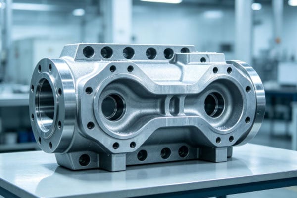
Precision Inspection and Machining Quality Control
Quality control for complex structural parts should cover pre-machining, in-process, and post-machining stages. For components with multiple machining references, complicated hole patterns, and spatial surfaces, ordinary calipers or individual dimensional measurements may not provide sufficient information about the finished part.
Manufacturers can use coordinate measuring machines, precision height gauges, bore gauges, thread gauges, and surface roughness testers to inspect critical dimensions and geometric tolerances.
Key quality control procedures include:
- Critical Dimension Inspection: Check overall length, width, height, wall thickness, hole diameters, and groove widths to confirm compliance with drawing tolerances.
- Geometric Accuracy Inspection: Measure flatness, parallelism, perpendicularity, concentricity, and positional tolerances to verify the spatial relationships between complex features.
- Hole and Thread Inspection: Inspect through-holes, blind holes, intersecting holes, and threaded connections to prevent burrs, chip blockage, and thread damage from affecting assembly.
- Surface Quality Inspection: Check surface roughness, tool marks, scratches, and localized machining defects according to component requirements.
- Material and Process Documentation: Verify material certificates, heat treatment records, and machining inspection reports according to project requirements to maintain production traceability.
- Special Performance Verification: Components used for pressure containment, sealing, or other safety-related functions should undergo pressure testing, leakage testing, or nondestructive testing as required by applicable standards and engineering specifications.
A complete inspection workflow helps identify machining deviations early and reduces the risk of nonconforming components entering the assembly process. For critical oil and gas equipment parts, acceptance criteria, inspection methods, and documentation requirements should be clearly defined to ensure that delivered quality can be verified.
The performance of complex structural parts is also influenced by material condition, heat treatment, surface treatment, and actual assembly conditions. For components exposed to corrosive environments, material resistance and surface protection requirements should be evaluated according to the operating media. For support components exposed to cyclic loads over extended periods, particular attention should be paid to stress concentration around structural transitions, hole edges, and thin sections.
Through appropriate design evaluation, CNC machining, and quality inspection, manufacturers can improve dimensional consistency and assembly reliability, providing dependable manufacturing support for oil drilling, oilfield monitoring, and energy processing equipment.