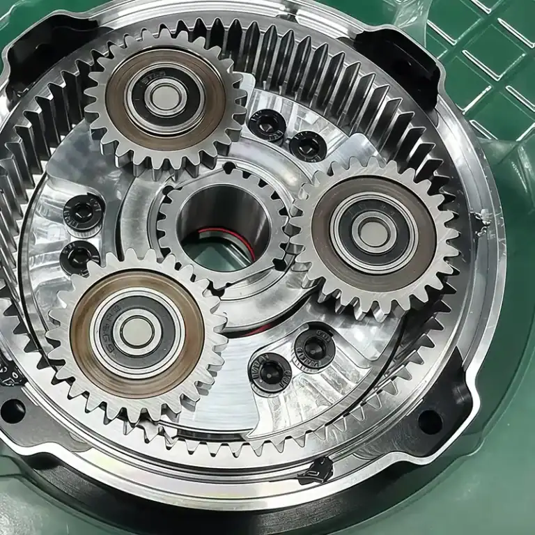
After running for a long time, an industrial gearbox may develop louder noise, excessive housing heat, or rough transmission. These problems are not always caused by insufficient lubrication. Poor machining quality can also be a contributing factor. Even a slight deviation in bearing positioning or dimensional errors on a gear shaft’s mating surface can place additional stress on internal components. For industrial equipment manufacturers, gearbox parts must meet drawing specifications and withstand long-term operation. With the right CNC machining processes, component fit can be improved, assembly errors reduced, and equipment performance made more reliable.
What Problems Can Poorly Machined Gearbox Components Cause?
Gearbox components are continuously exposed to torque, friction, and vibration. If even one part is not machined properly, the entire transmission system may be affected. This is particularly important for gearboxes used in industrial reducers, conveyor systems, and automated machinery, where long operating hours and changing loads place higher demands on component quality.

Why Can Gear Shaft Machining Errors Cause Abnormal Vibration?
Gear shafts need to maintain high rotational accuracy. If journal dimensions, shoulder positions, or concentricity are outside the required tolerances, the shaft may become misaligned after assembly and produce periodic vibration during operation.
- Inconsistent journal dimensions can affect bearing fit.
- Incorrect shoulder positions may shift the gear mounting location.
- Inaccurate keyway machining can weaken the reliability of the drive connection.
Can Incorrect Housing Hole Positions Affect Gear Meshing?
The gearbox housing supports bearings and transmission components. The spacing, parallelism, and positioning accuracy of its internal holes are all important. If these features are machined incorrectly, gear meshing may be affected, potentially accelerating tooth surface wear. Housing machining should therefore cover more than external dimensions. Bearing bores and internal locating features also require careful inspection.
Can Poorly Machined Seal Grooves Cause Oil Leakage?
Although the grooves on end covers, flanges, and seal housings are relatively small, they play an important role in keeping lubricating oil inside the gearbox. Incorrect groove depth, scratches on sealing surfaces, or mismatched mounting holes can increase the risk of oil leakage. CNC machining helps maintain groove dimensions according to engineering drawings and reduces the uncertainty associated with manual finishing.
Which Complex Gearbox Structures Are Suitable for CNC Machining?
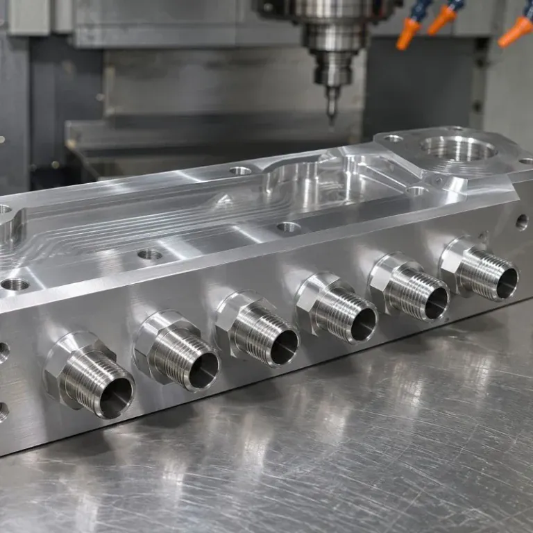
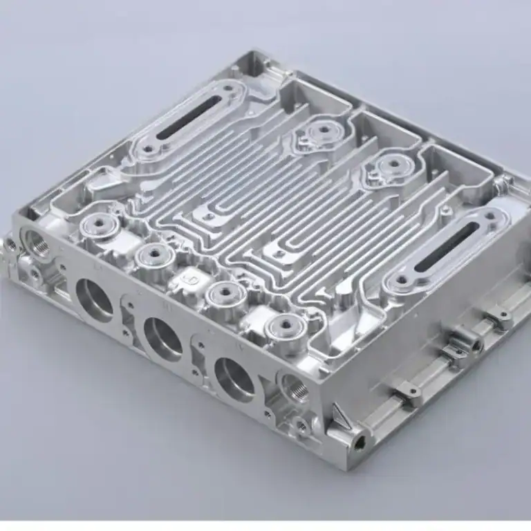
Gearbox components are not always simple cylinders or flat surfaces. Some housings contain deep cavities, intersecting holes, and angled mounting surfaces, while transmission shafts may combine steps, keyways, threads, and locating features. Repeated adjustments using conventional machining methods can increase setup time and positioning errors. CNC machining offers greater flexibility when processing complex profiles and precision features.
How Are Deep-Cavity Housings and Multi-Hole Structures Machined?
Deep-cavity housings have limited internal space. Tool rigidity, chip removal, and machining access can all become challenging when cutting tools extend into the cavity. The machining process needs carefully planned tool lengths, cutting parameters, and operation sequences to prevent chatter and inconsistent hole-wall quality.
How Can Complex Transmission Shafts Be Machined Accurately?
Some gearbox shafts have more than simple stepped profiles. They may include eccentric features, special keyways, and multiple mating surfaces. Depending on the design, CNC turning and milling or multi-axis machining can be used to reduce repeated setups and improve positioning consistency.
| Component Structure | Common Machining Challenges | Key CNC Machining Considerations |
| Deep-cavity housing | Limited tool access and difficult chip removal | Tool paths and cutting parameters |
| Multi-hole housing | Complex hole spacing and positioning | Consistent locating and hole inspection |
| Complex transmission shaft | Multiple profiles and eccentric features | Turning and milling coordination |
| Sealing end cover | Small grooves and demanding surface requirements | Groove depth and surface finishing |
How Can Thin-Walled End Covers and Lightweight Components Avoid Deformation?
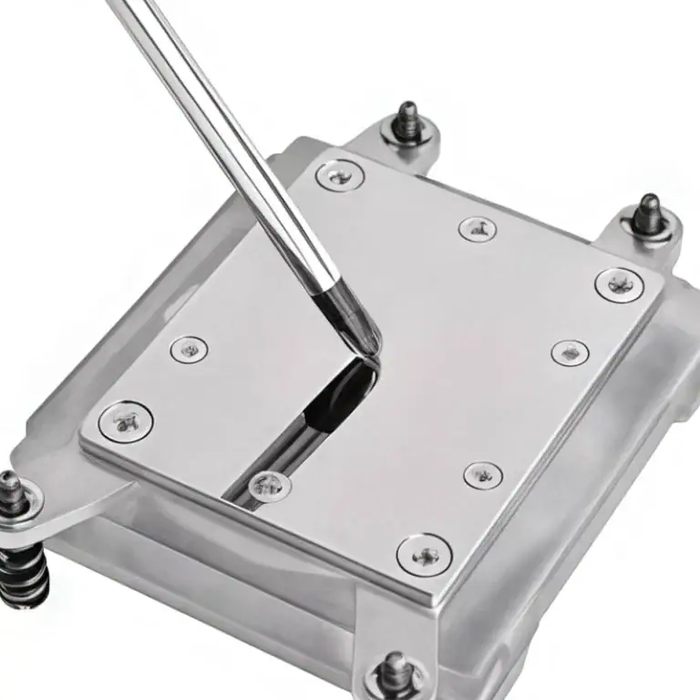
Some gearboxes use aluminum alloy end covers or thin-walled housings to reduce overall weight. These components have relatively low rigidity and may deform under excessive cutting forces. Flatness can also change after machining. Proper clamping force and staged material removal help reduce stress and prevent excessive deformation during production.
How Can CNC Machining Improve the Durability of Industrial Gearbox Components?
A component meeting its dimensional requirements immediately after machining does not automatically guarantee long-term performance. During operation, gearboxes experience continuous friction, impact loads, and temperature changes. Surface condition, material properties, and subsequent treatments all influence service life. Machining processes should be selected according to actual operating conditions rather than focusing solely on production speed.
Which Materials Are Suitable for Different Gearbox Components?
Gear shafts, support seats, and housings operate under different conditions, so they do not necessarily require the same materials. The following table shows common options. Final material selection should account for load, rotational speed, and the working environment.
| Component | Common Materials | Main Performance Requirements |
| Transmission shaft | 40Cr alloy steel and other alloy steels | Torque resistance and wear resistance |
| Gearbox housing | Cast iron, aluminum alloy | Structural support, heat dissipation, and weight reduction |
| Bearing support seat | Cast iron, carbon steel | Load capacity and dimensional stability |
| End cover | Aluminum alloy, carbon steel | Mounting, sealing, and connection |
How Can Component Wear Be Reduced During Long-Term Operation?
Bearing contact areas, shaft journals, and sealing surfaces are particularly exposed to friction. Several machining and finishing practices can help improve their performance:
- Maintain accurate mating dimensions and appropriate surface roughness.
- Remove burrs from holes, grooves, and component edges.
- Apply heat treatment or surface treatment according to operating requirements.
For transmission components carrying heavy loads, material hardness and toughness must also be properly balanced. Focusing only on surface hardness while ignoring overall mechanical properties may affect long-term reliability.
When Should Heat Treatment and Surface Treatment Be Performed?
Heat treatment can change component dimensions, while certain surface treatments may also affect final fit. The production sequence should be planned in advance, with sufficient machining allowance reserved for subsequent finishing. Critical features such as bearing seats, sealing surfaces, and locating surfaces should be inspected again after the relevant treatments to ensure proper assembly.
How Can Dimensional Consistency Be Maintained in Batch Production of Industrial Gearbox Components?
Industrial equipment manufacturers often need batches of identical gearbox components. Even small differences in hole spacing, shaft diameter, or mounting positions can complicate assembly and require additional adjustments. Batch machining must therefore control not only the accuracy of individual parts but also dimensional variation between production runs.
How Does CNC Machining Reduce Dimensional Differences Between Batches?
Stable machining datums and consistent program settings help reduce variations caused by manual operations. For repeat production, key locating methods, tool parameters, and inspection requirements can be standardized to maintain consistent machining conditions across batches.
Which Critical Dimensions Should Be Inspected During Batch Production?
Quality inspection should not be postponed until all machining operations are complete. Dimensional checks should be arranged at critical production stages.
- Shaft components: Check outer diameter, runout, and keyway dimensions.
- Housing components: Check hole spacing, bore diameters, and mounting surface positions.
- End covers: Inspect sealing grooves, mounting holes, and end-face dimensions.
- Finished components: Check appearance, burrs, and essential assembly dimensions.
What Production Details Should Be Confirmed Before Custom Machining?
In addition to engineering drawings, manufacturers should confirm order quantities, material specifications, surface treatments, inspection requirements, and delivery schedules. If the components are intended for gearbox repairs, existing part dimensions or 3D models can also help clarify the original mounting relationships and reduce production changes.
Long-term gearbox reliability depends on how accurately its individual components fit and work together. Whether the project involves complex housings, transmission shafts, or sealing end covers, precise machining helps reduce assembly problems and abnormal wear. If you are developing industrial equipment or need custom gearbox components, TIRAPID provides CNC machining services based on your drawings and application requirements. Contact us to discuss your project.