CNC turning tools directly affect machining accuracy, surface roughness, production efficiency, and manufacturing costs. For automotive components, automation equipment, industrial connectors, and precision mechanical parts, the right tools help manufacturers reduce tool changes, control dimensional deviations, and maintain consistent quality during batch production. Different metal materials, part geometries, and machining requirements call for specific insert materials, cutting-edge geometries, coating properties, and tool rigidity. Understanding how to select CNC turning tools helps manufacturers develop more reliable machining processes and supports both custom precision parts and high-volume production.
Key Factors in CNC Turning Tool Selection
When selecting CNC turning tools, manufacturers should consider workpiece material, part geometry, machining accuracy, production volume, and machine capability. Choosing tools based only on price or a single cutting parameter may shorten tool life, reduce surface quality, or increase the risk of scrapped components. Clearly defining drawing requirements and actual machining conditions makes it easier to select suitable tools and cutting parameters.
Select Tools Based on Workpiece Material
The hardness, toughness, thermal conductivity, and work-hardening characteristics of a material affect tool wear and cutting stability. Different materials require appropriate insert grades, cutting-edge preparations, and coating combinations.
- Aluminum alloys: Aluminum alloys generally offer good machinability, but some grades are susceptible to built-up edge and material adhesion. Sharp cutting edges, suitable rake angles, and effective chip evacuation help improve surface finish and reduce burrs. For aluminum components with strict appearance or dimensional requirements, the tool and parameter combination should be verified through trial machining.
- Stainless steel: Stainless steel can be relatively tough, and certain grades are prone to work hardening. Tools should provide suitable wear resistance and resistance to edge chipping. Stable feed rates, appropriate cutting depths, and effective cooling help reduce the impact of work hardening on tool life.
- Carbon steel and alloy steel: These materials are commonly used for shafts, connectors, and mechanical structural components. Tool selection should reflect material hardness, heat-treatment condition, and machining stage. Roughing emphasizes tool strength and impact resistance, while finishing requires dimensional stability and good surface quality.
- Titanium alloys and high-temperature alloys: These materials may have low thermal conductivity, high cutting temperatures, or relatively rapid tool wear. Tool grade, coating, cutting speed, and cooling methods should be validated for the specific application rather than copied directly from standard steel machining parameters.
- Engineering plastics: When turning plastic components, sharp tools, effective chip evacuation, and heat control are important. These measures help prevent material softening, deformation, and surface burrs. For precision plastic parts, clamping force must also be controlled to minimize workpiece distortion.
Confirming the material grade and delivery condition is an essential starting point for tool selection. For projects involving different material batches or recurring orders, recording validated tool specifications and machining parameters helps improve production consistency.
Determine the Tool Type Based on Part Geometry
Part shape, internal hole depth, groove width, thread specifications, and available machining space all influence tool design and dimensions. Standard turning tools may be sufficient for conventional cylindrical parts, while internal holes, narrow grooves, and specialized profiles often require dedicated tools or more detailed process planning.
- External diameter and facing operations: Select external turning or facing tools according to the part diameter, cutting allowance, and surface requirements. Tool mounting height, holder rigidity, and cutting-edge angles should match the workpiece geometry.
- Internal boring: Deep holes and small-diameter bores require careful consideration of boring-bar diameter, overhang, and chip evacuation. Excessive tool overhang or insufficient rigidity can cause vibration, dimensional deviations, and poor surface finish.
- Grooving and parting-off: Groove width, depth, and cutting position determine insert dimensions and holder strength. Narrow grooving tools can reduce material waste, but they require stable clamping and effective chip evacuation to avoid excessive insert loads.
- Threading: Select the appropriate threading insert according to metric, imperial, or specialized thread specifications. Verify the pitch, thread profile angle, and effective thread length. For high-precision threads, the tool geometry and CNC program should be validated before production.
- Complex profiles: For arcs, shoulders, irregular grooves, or specialized contours, form tools or dedicated tooling may be appropriate. Depending on production volume and profile tolerances, they can reduce repeated passes and improve consistency.
When planning a machining process, confirm that the tool can reach the cutting area without interfering with the chuck, tailstock, or other parts of the workpiece. A well-planned machining sequence helps reduce unnecessary tool changes and improves the efficiency of complex part production.
Consider Tolerances, Surface Finish, and Order Volume
High-precision parts require a stable tooling system and strict process control. Tool nose radius, insert wear, tool-holder vibration, and machine thermal changes can all affect dimensions and surface quality. Tool selection should consider not only cutting speed but also process stability throughout the production cycle.
Small-batch orders often prioritize tool-change convenience, machining flexibility, and setup time. High-volume production places greater emphasis on tool life, cycle time, tool-change frequency, and unit cost. For parts with tight dimensional tolerances or demanding appearance requirements, validate tool performance through trial machining and first-article inspection before applying the configuration to subsequent production.
Common CNC Turning Tools and Their Applications
CNC turning tools come in various types, each designed for specific machining tasks, cutting directions, and structural requirements. Selection should be based on engineering drawings, material properties, and machine configuration to ensure the tool meets the required accuracy, efficiency, and service-life expectations. Common options include external turning tools, internal boring bars, threading tools, grooving tools, and form tools.
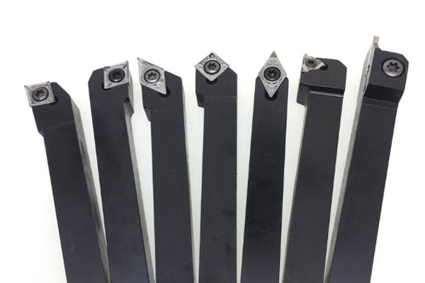
External Turning Tools and Finishing Inserts
External turning tools are used to machine the outer diameters, end faces, and shoulders of shafts, sleeves, and other rotational components. Different insert shapes, nose angles, and holder designs can be selected according to cutting direction, workpiece geometry, and machining allowance.
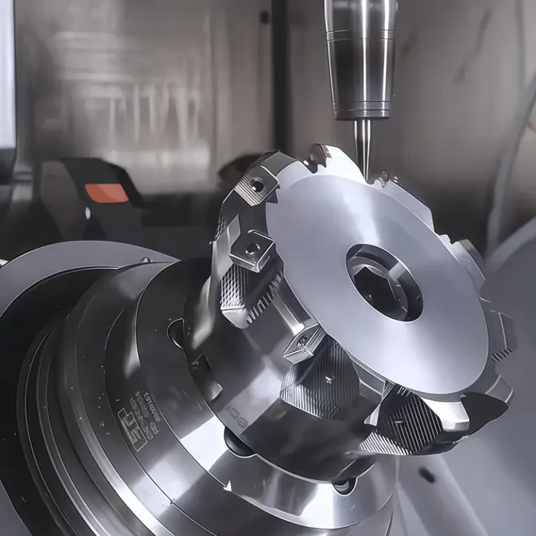
- Roughing inserts: These are used to remove larger amounts of material and generally require strong cutting edges, impact resistance, and wear resistance. Appropriate chipbreaker geometry improves chip control and reduces the risk of chip entanglement during continuous production.
- Finishing inserts: These are designed to control final dimensions and surface quality. A suitable nose radius, sharp cutting edge, and stable tool installation help reduce surface marks and improve dimensional consistency.
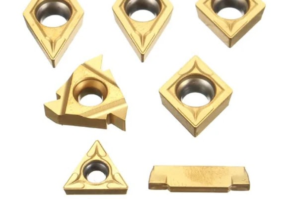
- Indexable inserts: These inserts can be rotated or replaced when worn, making standardized tool management easier. They are suitable for repeat machining and batch production. Buyers should verify the insert model, grade, coating, and compatibility with the tool holder.
Using separate tool configurations for roughing and finishing helps balance material removal efficiency with final surface quality. For precision shafts, manufacturers should also consider clamping length, workpiece overhang, and the potential for vibration during machining.
Internal Boring Bars and Grooving Tools
Internal boring bars are used to machine bore diameters, internal shoulders, and cylindrical surfaces. Because the tool must enter the workpiece, available space is often limited by bore diameter and depth. Select a boring bar that provides sufficient rigidity while fitting within the machining space, and control overhang as much as possible. Deep-hole machining requires particular attention to chip evacuation, coolant delivery to the cutting zone, and vibration control.
Grooving tools are used for external grooves, internal grooves, face grooves, and parting-off operations. Groove width and depth determine the required insert dimensions and holder strength, while bottom radii and sidewall requirements influence insert geometry. In narrow-groove machining, tool deflection, chip blockage, or unstable feed can cause width deviations and surface damage. Before machining, confirm the insert width, cutting direction, groove depth, and retract path. Multi-stage cutting may be necessary to improve chip evacuation.
When a component includes external diameters, internal bores, and multiple grooves, the machining sequence should be planned according to tool accessibility and tool-change time. An appropriate combination of tools reduces unnecessary repositioning and improves production efficiency.
Threading Tools and Form Tools
Threading tools are used to produce external and internal threads. Common options include indexable threading inserts and solid threading tools. Selection requires confirmation of the thread standard, pitch, profile angle, direction, and effective length. If the tool does not match the target thread specification, the finished part may have an incomplete profile, an excessively tight fit, or unacceptable thread dimensions, even when the CNC program is correct.
Form tools are used for rotational components with specific contours, grooves, or repeated profiles. Under suitable machining conditions, they can reduce the number of tool passes and improve profile consistency. However, form tools generally require careful selection for the part geometry, and their cutting loads may be higher than those of conventional turning tools. For small-batch orders or frequently revised designs, compare the cost of dedicated tooling with the machining time required for general-purpose tools before deciding which approach to use.
For precision threads and complex profiles, tool selection should be coordinated with CNC programming, inspection methods, and part tolerances. Trial machining helps identify potential tool interference, poor chip evacuation, and profile deviations before full-scale production.
How to Extend CNC Turning Tool Life and Control Costs
Tool life affects machining cycle time, machine utilization, and unit manufacturing costs. Simply increasing cutting speed may accelerate tool wear and increase tool-change frequency and downtime. A more effective approach is to establish a tooling management process tailored to the material and machining task, using parameter validation, wear monitoring, and quality inspection to maintain stable production.
Optimize Cutting Speed and Feed Parameters
Cutting speed, feed rate, and depth of cut should be matched to the material, insert grade, machining stage, and machine capability. Excessive parameters can increase cutting temperatures, cause tool-tip wear, or lead to edge chipping. Parameters that are too low may reduce productivity and, for certain materials, increase friction or work-hardening risks.
- Adjust speed to the material: Use the tool manufacturer’s recommended ranges as a starting point, then verify them through trial machining based on workpiece hardness, material condition, and actual cutting performance. Different materials should not automatically use identical speed settings.
- Maintain a stable feed rate: Feed rate affects chip thickness, surface texture, and cutting load. During finishing, select a suitable feed based on the required surface roughness and tool nose radius.
- Set an appropriate depth of cut: Roughing should balance material removal rate with tool load capacity. Finishing requires a stable and controlled allowance to prevent uneven material removal from affecting final dimensions.
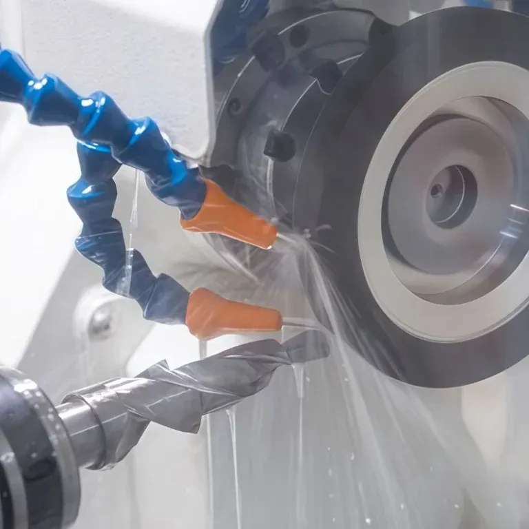
- Improve cooling and chip evacuation: Use an appropriate cooling method for the material and tool, and ensure chips are removed efficiently. If chips wrap around the tool or repeatedly contact the finished surface, adjust the chipbreaker strategy or machining parameters.
Parameter optimization should be evaluated using actual production results. Recording machining time, tool wear, surface quality, and dimensional changes helps operators identify settings that balance productivity, quality, and tool life.
Establish Tool Inspection and Replacement Standards
If tools are used until severe wear occurs, multiple parts may develop dimensional deviations or unacceptable surface roughness before the tool is replaced. Clear inspection intervals and replacement criteria help manufacturers intervene before quality problems spread.
- Inspect cutting edges regularly: Check for wear, chipping, built-up edge, and abnormal discoloration. For high-precision components, inspection intervals should reflect production volume and actual quality performance.
- Record tool life: Track usage by material, tool model, cutting parameters, and machining task. These records make it easier to compare the consistency of different tooling solutions.
- Check tool holders and clamping systems: Loose holders, incorrect insert installation, or excessive tool overhang can cause vibration and dimensional changes. After replacing an insert, verify its position and clamping condition.
- Connect tool records with inspection results: Linking tool replacement records to dimensional measurements helps identify relationships between tool wear and dimensional drift, supporting more effective preventive replacement schedules.
For ongoing production orders, standardized tool management reduces unplanned downtime and helps maintain consistent machining quality across different shifts.
Reduce Unit Costs Through Process Planning
CNC turning tool costs include more than the purchase price of inserts or tools. They also include tool-change time, machine downtime, cycle time, scrapped parts, and quality inspection costs. A low-cost tool does not necessarily produce the lowest overall manufacturing cost. Its performance under actual operating conditions is what matters.
For batch orders, compare tool life, machining cycle time, and surface quality to estimate the actual cost per conforming part. For small-batch custom components, prioritize setup time, versatility, and ease of tool changes to avoid unnecessary investment in dedicated tooling for limited production quantities.
When purchasing CNC machining services, provide the supplier with complete part drawings, material grades, critical tolerances, surface roughness requirements, and estimated order quantities. The supplier can use this information to evaluate tooling configurations, machining sequences, and inspection plans, then validate process feasibility through sample production before approving full-scale manufacturing. Clear technical requirements reduce repeated communication and rework while helping quotations reflect the actual machining requirements more accurately.
CNC turning tool selection requires consideration of material properties, part geometry, machining accuracy, and order volume. Choosing suitable turning tools, boring bars, grooving tools, threading tools, and form tools, combined with appropriate cutting parameters and tool-life management, improves machining stability and reduces production waste. For businesses requiring custom precision metal parts, working with a CNC machining supplier that offers established process planning, standardized inspection, and reliable tooling management helps improve delivery quality and control long-term purchasing costs.