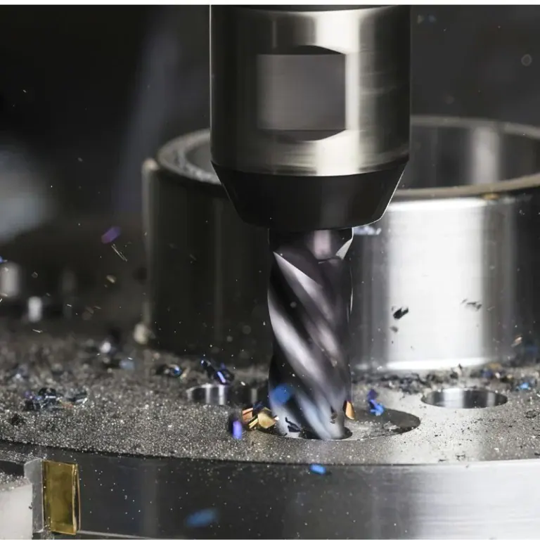
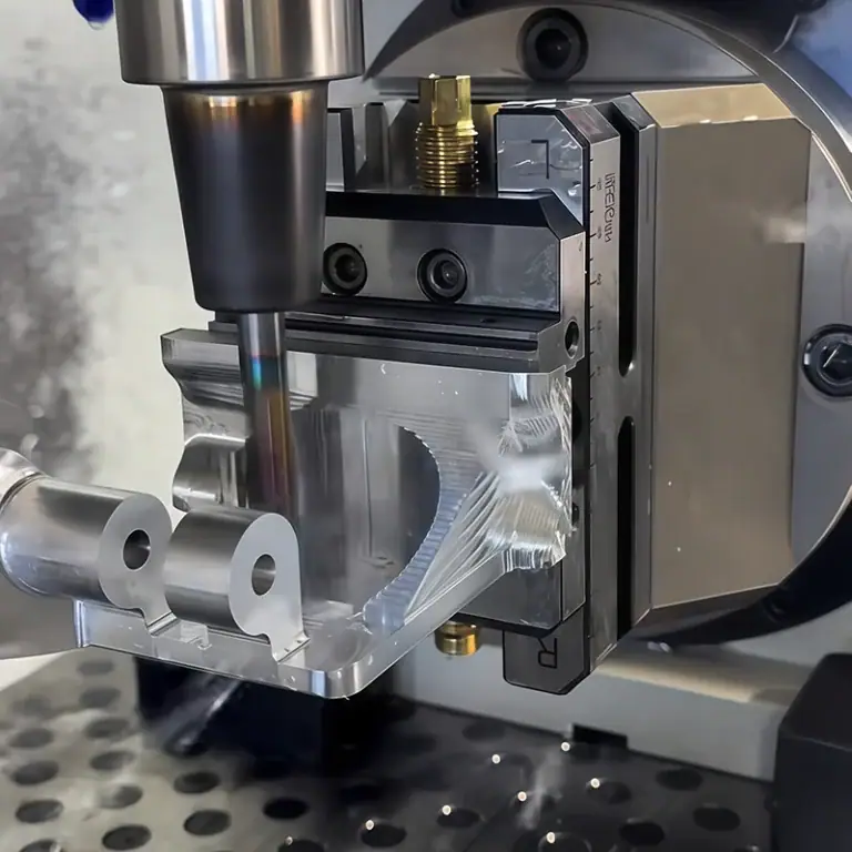
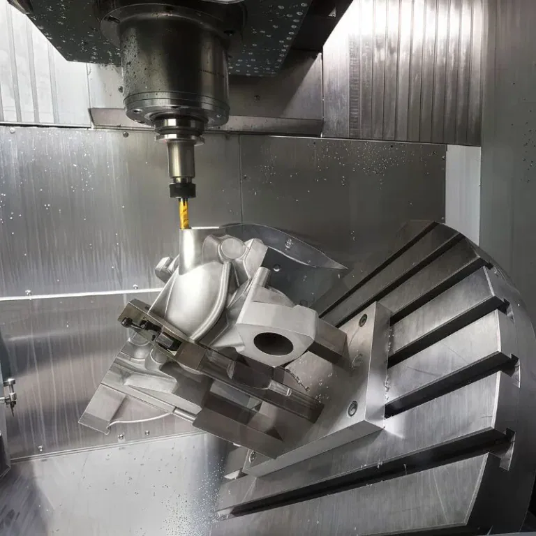
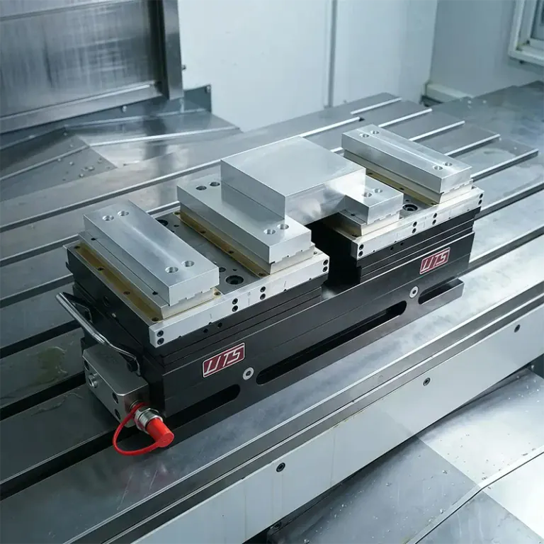
The mechanical structures of automation equipment support, position, and connect various functional components. Their machining quality directly affects equipment assembly, operational stability, and long-term maintenance. Complex parts with multiple machined faces, deep cavities, irregular grooves, and precision mounting holes can be difficult to manufacture while maintaining both dimensional accuracy and production efficiency. When developing a CNC machining solution, manufacturers should plan machining operations and inspection procedures according to the part’s manufacturing requirements. This helps reduce quality-related costs and improve compatibility between components and the equipment.
Machining Challenges for Complex Structural Components in Automation Equipment
Complex structural components often contain multiple geometric features, making positioning, tool accessibility, and dimensional relationships important considerations during machining.
Multi-Side Machining and Complex Contours
Different features require appropriate toolpaths and workholding methods, so machining feasibility should be evaluated before production.
- Multi-Side Structures: Multiple machined faces have positional relationships that must be maintained. A suitable machining sequence helps reduce positioning errors caused by repeated setups.
- Deep Cavities and Narrow Slots: Tool reach, chip evacuation, and machining accessibility must be considered to reduce the risk of tool interference and surface defects.
- Irregular Contours: Curved surfaces, angled faces, and irregular boundaries require toolpaths based on engineering drawings, along with appropriate machining allowances.
Analyzing part features in advance helps determine suitable machining methods and equipment configurations.
Assembly Accuracy and Deformation Control
Structural components often interface with guide rails, actuators, sensors, and other mechanical parts. The relationships between critical dimensions are therefore just as important as individual measurements.
- Mounting Holes and Locating Surfaces: Control hole diameters, hole spacing, and datum relationships to ensure accurate installation.
- Thin-Walled Structures: Manage clamping forces and cutting loads to reduce potential deformation during machining.
- Mating Areas: Define dimensional tolerances and surface quality requirements according to assembly functions to avoid excessive machining or insufficient accuracy.
Incorporating assembly requirements into process planning helps reduce trial fitting and subsequent adjustments.
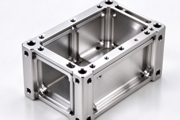
Material Selection and CNC Machining Process Planning
Material properties, part geometry, and machining requirements are closely related and should be considered together during process planning.
Select Materials According to Application Requirements
Material selection should balance structural strength, weight, corrosion resistance, machinability, and cost.
- Aluminum Alloys: Lightweight and generally easy to machine, making them suitable for certain mounting bases, brackets, and equipment housings.
- Stainless Steel: Suitable for components requiring specific levels of corrosion resistance or strength, although machining difficulty and manufacturing costs must be considered.
- Carbon Steel and Other Engineering Materials: Can be selected according to load-bearing capacity, rigidity, and operating conditions.
Materials should match the equipment’s actual operating requirements to avoid unnecessary machining difficulties or reduced performance.
Arrange Machining Operations Efficiently
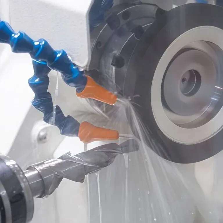
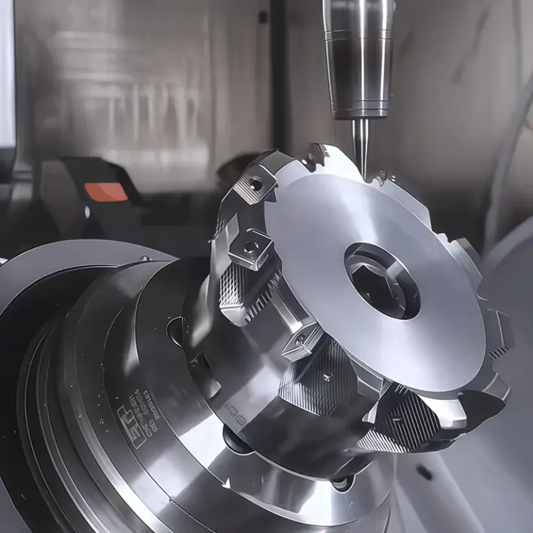
Complex structural components often require multiple machining operations. Their sequence affects dimensional stability and production efficiency. Rough machining removes the main material allowance while leaving sufficient stock for finishing and accounting for potential stress-related changes. Finish machining focuses on datum surfaces, critical hole positions, and mating areas to meet drawing requirements. Workholding and positioning should use suitable datums based on part geometry to minimize repeated setups. Toolpaths for deep cavities, narrow slots, and complex contours should account for tool movement and chip evacuation to prevent interference and overcutting. A well-planned sequence helps balance quality, efficiency, and cost.
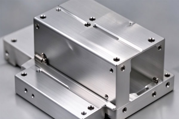
Quality Inspection and Process Control for Complex Structural Components
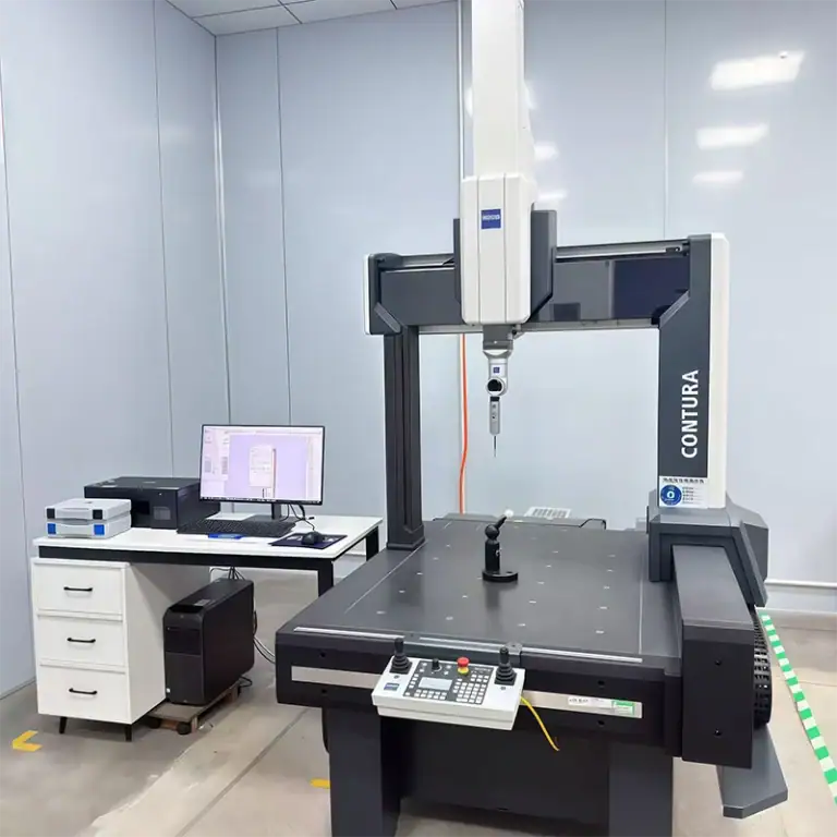
Quality inspection should be based on engineering drawings and actual assembly requirements to ensure that critical features meet acceptance criteria.
Define Critical Dimensions and Inspection Items
Key inspection items, measurement methods, and acceptance criteria should be established before production to avoid discrepancies during final acceptance.
| Inspection Item | Key Areas to Check | Main Purpose |
| Overall Dimensions | Length, width, thickness, and contours | Ensure overall dimensions meet drawing requirements |
| Hole Positions and Spacing | Mounting-hole locations, diameters, and spacing | Meet connection and installation requirements |
| Datum Surfaces | Flatness, parallelism, and positional relationships | Ensure accurate assembly positioning |
| Complex Contours | Curved surfaces, deep cavities, and irregular features | Verify geometric features against design requirements |
| Surface Quality | Burrs, scratches, and machining marks | Reduce potential assembly problems |
Measurement tools should be selected according to the component’s accuracy requirements and geometry, with particular attention to dimensions that affect installation and fit.
Maintain Consistent Quality Across Production Batches
For structural components that require repeat orders, manufacturing consistency affects equipment assembly efficiency. Key operations and inspection results should be recorded, and critical dimensions should be monitored during production. When deviations occur, possible causes such as tool wear, workholding conditions, and cutting parameters should be investigated. Ongoing process checks help reduce dimensional variation between batches.
How to Choose a CNC Machining Supplier for Complex Structural Components
Purchasers should evaluate a supplier’s technical communication, machining capabilities, and delivery management to ensure that the manufacturing solution meets project requirements.
Provide Complete Engineering Documentation
Clear technical documentation helps suppliers assess machining challenges, plan operations, and estimate costs accurately.
- Provide 2D engineering drawings, 3D models, material requirements, and critical dimensional tolerances.
- Identify mounting datums, mating areas, complex contours, and surface finishing requirements.
- Specify prototype quantities, production volumes, delivery schedules, and potential design changes.
Confirming technical information in advance helps reduce quotation discrepancies and repeated communication during production.
Confirm Inspection and Delivery Requirements
Before production begins, clarify dimensional inspection, first-article approval, surface finishing, packaging, and delivery requirements. For components with complex geometries or multiple assembly interfaces, prototype machining can be used to verify critical dimensions and installation relationships before batch production, reducing the risk of large-scale rework.
Machining complex structural components for automation equipment requires a manufacturing process tailored to part geometry, material properties, and assembly requirements. Optimizing workholding methods, machining sequences, and inspection procedures helps reduce assembly adjustments, improve part consistency, and control procurement and production costs. TiRapid provides customized precision CNC machining services based on customer drawings, material specifications, and order requirements to support the production of complex structural components for automation equipment.