In industrial design and high-end manufacturing, polytetrafluoroethylene (PTFE) is known as the “king of plastics” for its superb temperature resistance, non-stickiness and chemical inertness. However, its CNC processing is not easy. Because of its soft material, low rigidity, and easy drawing during cutting, many engineers will encounter problems such as difficult precision control and poor surface quality in actual operation. This article will start from the basic properties of PTFE, combined with my processing experience in the medical, semiconductor, electrical and other industries, to systematically explain whether PTFE can be processed by CNC, how to process it, what problems will be encountered and how to apply it, to provide you with a systematic and practical processing reference guide.
What Is PTFE
Polytetrafluoroethylene (PTFE) is a polymer fluoroplastic material. In many projects I have participated in that require high cleanliness, high corrosion resistance, and high insulation, PTFE is frequently used due to its excellent physical and chemical properties. It is a linear polymer formed by the polymerization of tetrafluoroethylene monomers and has extremely high molecular stability and inertness. As a thermoplastic material, although it cannot be formed by ordinary melt processing, it can be efficiently CNC turned and milled, and is widely used in sealing, insulation, and chemical corrosion resistance scenarios.
The molecular chain of PTFE is composed of a large number of carbon-fluorine bonds, and the carbon-fluorine bond energy is as high as 485 kJ/mol, which is one of the most stable bonds among all plastics. This makes PTFE have excellent high temperature resistance and chemical corrosion resistance.
It maintains stable performance between -180°C and 260°C, does not melt, and only undergoes thermal decomposition at around 327°C, making it suitable for extreme environments such as plasma etching, ultra-high vacuum equipment, etc.
In medical projects, I have used PTFE to make the core components of infusion valves. Its non-adhesive surface and biocompatibility make it the preferred material for disposable devices . In semiconductor equipment, I have also used PTFE to make the lining of plasma reactors. After 6 months of use, there was no obvious corrosion or performance degradation.
In addition, PTFE has a dielectric strength of 60–100 kV/mm, a volume resistivity of more than 10¹⁸ Ω·cm, and almost zero moisture absorption, making it an ideal insulating material. As a result, it can perform critical tasks in high-frequency communications, high-voltage electrical, and chemical reaction environments.
In summary, PTFE is not an ordinary “engineering plastic”. It has extremely high performance in multiple dimensions of thermal, chemical, mechanical and electrical performance. For me, as long as the project requires the “extreme reliability” of the material, PTFE is usually the first choice.
What Are The Characteristics Of PTFE Materials
In my many years of processing projects, polytetrafluoroethylene (PTFE) has always been one of the most comprehensive and stable engineering plastics. It has multiple advantages such as high temperature resistance, extremely low friction coefficient, strong non-stickiness, and extremely high corrosion resistance. It is particularly suitable for applications that require high insulation, low wear or resistance to chemical media. Compared with common materials such as PA, PEEK, POM, etc., PTFE is more stable in extreme environments and is an important material that I repeatedly choose in medical, semiconductor and food equipment projects.
High Temperature Resistance (-180°C to 260°C)
PTFE has excellent thermal stability and can maintain mechanical properties for a long time in the temperature range of -180°C to 260°C. Its decomposition temperature is about 327°C, and it will carbonize directly instead of melting. This property allows me to work with projects involving high-temperature valve seats, heat-resistant seals, etc. without worrying about the material softening and deforming due to temperature rise.
I once tested a PTFE seal in a battery thermal management project. After running at a continuous temperature of 240°C for 100 hours, the dimensional change rate was less than 0.01%, which fully met the thermal stability requirements.
Friction Coefficient As Low As 0.04
The friction coefficient of PTFE is about 0.04, which is one of the lowest among known solid materials. It can maintain extremely low wear even without lubrication. This feature makes it widely used in low-friction scenarios such as sliders, guide rails, and valve cores. A batch of slide rails for automatic filling machines that I processed still had a smooth surface without scratches after running 3 million times, which is much better than PE or nylon materials.
Strong Non-Stick Property, Easy To Clean
PTFE has extremely low surface energy, and almost no substance can adhere to its surface for a long time, which also makes it have excellent non-stick properties. I have used PTFE as a contact surface material in the food packaging industry. Even in the face of high sugar and high oil environments, cleaning and maintenance are extremely convenient, reducing the frequency of equipment cleaning.
Chemical Inertness And Solvent Resistance
PTFE has excellent chemical stability to almost all acids, bases, alcohols, ketones and organic solvents. The carbon-fluorine bond in its molecular structure is highly stable, making it usable in highly corrosive media environments. In a hydrofluoric acid delivery system renovation, we selected PTFE gaskets, which were continuously operated for one year without any leakage or corrosion.
Electrical Insulation Properties And Dielectric Strength
PTFE has a dielectric strength of 60–100 kV/mm and a volume resistivity of 10¹⁸ Ω·cm, making it an indispensable insulating material in high-frequency electrical and high-voltage systems. I have used it in high-voltage power supply insulation brackets, which can continuously carry 22kV voltage without breakdown, far exceeding the withstand voltage level of ordinary plastics.
Food Grade, Biocompatible
Pure PTFE is non-toxic and odorless, complies with FDA and USP Class VI standards, and is suitable for contact parts in food and medical equipment. In a medical pump project, the customer required that the conveyed liquid should not come into contact with any dissolved substances. We selected PTFE to manufacture the fluid path connector and passed the full set of ISO 10993 biocompatibility tests.In summary, the core features of PTFE are not only “temperature resistance” and “anti-sticking”, but also its high-end performance in the four dimensions of heat, electricity, force and chemistry. Among all engineering plastics, I think it is one of the most suitable materials for “extreme working conditions”.
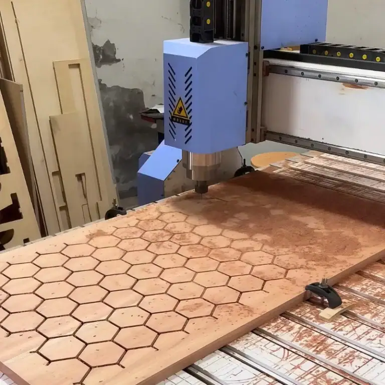
Can PTFE Be Processed By CNC
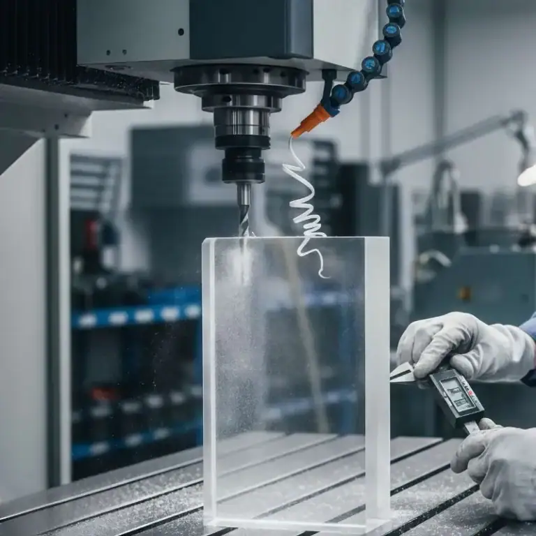
Yes, PTFE can be processed by CNC, and in my actual operation, it has become one of the conventionally processable materials. But it must be admitted that compared with engineering plastics such as POM and PEEK, PTFE is much more difficult to process. Because it is soft, slippery, and easy to draw, CNC processing requires special adjustments to the equipment, tools, and processing parameters to obtain ideal dimensional accuracy and surface quality.
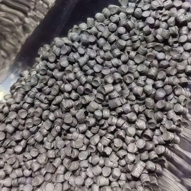
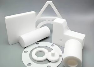
PTFE Forms Suitable For Processing (Rods, Sheets)
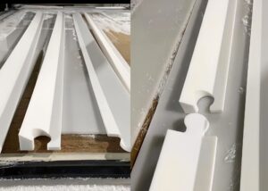
In actual processing, I usually choose PTFE rods with a diameter of φ10–φ300 mm or plates with a thickness of 2–50 mm as blanks. PTFE is highly flexible and is not suitable for structures that are too thin or too long, especially because it is prone to vibration and deformation during turning. By encapsulating the clamping port, I can effectively avoid clamping marks and indentations and improve material utilization.
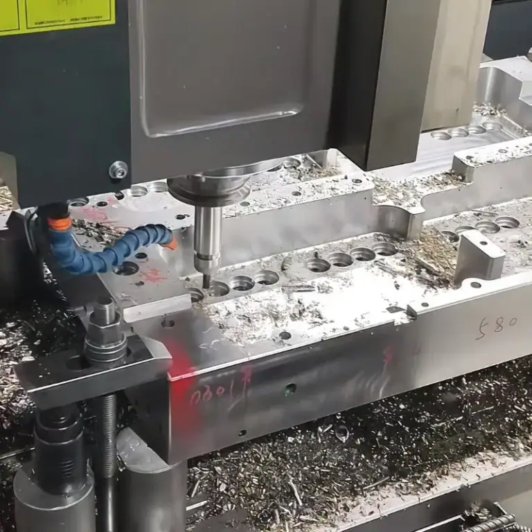
Feasibility Analysis Of Turning, Milling And Drilling
PTFE can be used for conventional CNC turning, plane milling and deep hole drilling. When turning, I tend to use a larger tool tip radius (≥0.4 mm) to reduce cutting stress. When milling, it is recommended to use a double-edged or three-edged tool to reduce unit cutting pressure. For drilling, I have used a φ2.0 carbide drill to process a 15 mm deep through hole, combined with a 1:5 advance and retract strategy, which effectively avoids “drawing” and “collapse”.
Effect Of Different Grades Of PTFE On Processability (Filled Vs Pure)
I would like to remind you that different grades of PTFE have huge differences in processing performance. Pure PTFE is soft, easy to deform, and has good surface quality but difficult to control dimensions . However, the hardness, rigidity and thermal expansion stability of glass fiber filled, carbon filled or bronze filled PTFE are significantly improved, and the processing accuracy is significantly improved. I have successfully processed a batch of ±0.02 mm precision positioning rings using 25% glass fiber reinforced PTFE. Later, customers used them in plasma etching machines and the stability exceeded expectations.
In summary, although PTFE has certain processing challenges, as long as the appropriate material specifications, tool types and process parameters are selected, CNC processing is completely feasible, and the processing effect is stable and repeatable. For parts with high corrosion resistance, low friction and high insulation requirements, CNC processed PTFE is still one of the first choices.
What To Pay Attention To When Processing PTFE
The most common problems I encounter in PTFE processing projects are customer feedback about “rough surface”, “dimensional deviation” or “material edge collapse and wire drawing”. These phenomena are due to the low hardness, high elasticity and thermal deformation characteristics of PTFE. Although PTFE is a very suitable material for insulation, corrosion resistance and low friction, special attention must be paid to tools, speeds, cooling and clamping methods in CNC processing, otherwise there will be problems such as unstable accuracy, whitening of the surface or high processing scrap rate. Based on my experience in mass production of medical sealing rings and electrical insulation blocks, as long as the correct parameters are mastered, PTFE can also be stably and efficiently processed in batches.
Tool Selection (Carbide Vs PCD)
I recommend using ultra-fine-grain carbide tools or PCD tools (polycrystalline diamond) , especially when processing large quantities continuously. PCD has better wear resistance and can last for more than 10 hours. A sharp tool tip (recommended 0.2-0.4 mm radius) can reduce cutting resistance and prevent material chipping or burring. If a standard steel tool is used, even if it is not filled with PTFE, the blade will quickly become blunt, resulting in brushing or a fuzzy surface.
Processing Speed And Feed Setting Recommendations
PTFE cannot be cut at high speeds. I usually control the spindle speed to 400-800 rpm and set the feed rate to 0.05-0.15 mm/rev . The cutting depth should not exceed 0.5 mm at a time, especially when machining thin walls or small parts. If you want higher surface quality, you can reduce the feed rate to 0.03 mm/rev and use multiple light cuts.
How To Reduce Material Drawing And Deformation
PTFE is easy to draw when the tool is cut out. I use the combination of “fast chip breaking + negative rake angle tool” to reduce the drawing length. For precision structures, I will use flexible elastic fixtures with low clamping force or silicone coating to fix the workpiece to avoid indentation or extrusion deformation caused by the fixture. The cooling method can also be changed to air cooling or wind cooling to avoid micro cracks caused by uneven thermal shrinkage caused by liquid cooling.
Surface Finish Control Tips
PTFE has good “self-lubricating” properties, so it is easy to leave small attachments on the surface during cutting. I usually use a 0.2R fine turning tool with a 0.05 mm feed, and finally use a high speed to quickly scan the surface once, so that the surface reaches Ra < 1.6 μm , which meets the finish requirements of the medical and electronics industries. If brushing marks appear, I will use a slight polishing or deburring process to make the surface more uniform and delicate.
In summary, although PTFE processing is difficult, high-yield CNC precision processing can be achieved as long as the tool sharpness, cutting parameters and clamping stress are well controlled. In my experience, a set of scientific processing technology can make the instability of PTFE controllable and adapt to the size and performance requirements of high-end applications.
What Are The Common Problems In PTFE Processing
Even in experienced processing plants, PTFE parts are prone to dimensional deviation, surface roughness, and even direct scrapping. This is because PTFE’s low rigidity, high thermal expansion coefficient (about 120×10⁻⁶/°C), and extremely deformable structural characteristics determine that it is extremely sensitive to cutting parameters and environmental changes. In the projects I am responsible for, especially in batch processing for medical seals, electronic insulation blocks, and corrosion-resistant gaskets, almost every one of these problems has been encountered personally. The following are the four most common problems I have summarized and their coping strategies.
Causes And Solutions For Size Deviation
PTFE has a high elastic recovery rate, and during processing, it will cause “rebound” due to tool extrusion, which will eventually cause the measured size to be inconsistent with the program size. When I process valve seats with a precision requirement of ±0.02 mm, I often “enlarge” the size by 0.03 mm before trial assembly to ensure stable shrinkage after cooling. In addition, using low clamping force fixtures and multiple light cuts can effectively reduce dimensional errors caused by thermal deformation.
Common Manifestations And Treatment Methods Of Rough Surface
Whitening, burrs, and even “brushing” are common phenomena in PTFE processing, especially in milling and external turning. If the tool is not sharp enough, the cutting temperature is too high, or the chip removal is not smooth, the surface roughness is likely to exceed Ra 3.2 μm . I usually use PCD tools + dry cutting , and use a small feed rate (<0.05 mm/rev) for finishing in the last 0.1 mm layer, which can often stably achieve a surface quality below Ra 1.6 μm .
Causes And Prevention Methods Of Material Cracking And Deformation
Although PTFE is tough, it is easy to produce stress concentration when clamped too tightly or locally overheated, causing cracking and deformation of thin-walled parts . For example, I once encountered a PTFE ring with a diameter of 25 mm that cracked in the drill hole. After rechecking, it was found that the clamping pressure was too high + the feed rate was too high. To deal with this kind of problem, I recommend using rubber/silicone soft clamps and spiral drilling or step drilling to reduce instantaneous cutting forces, which is especially suitable for internal hole processing.
“Remediation” Techniques After Problems Occur During Processing
If there are problems such as dimensional deviation and surface burrs during processing, they can sometimes be remedied by secondary finishing, light polishing or tool change finishing . For slightly brushed surfaces, I often use sponge sand + low-speed manual polishing to improve, and try to retain the original structure and function of the parts. If the functional parts cannot be polished, it is necessary to readjust the program parameters and start again from the material blank.
In general, the difficulty of PTFE processing is not “cannot be processed”, but “how to control risks”. Mastering the material behavior characteristics, matching reasonable parameters and flexible fixture systems are my usual approach to dealing with such problems, and are also the key capabilities of a qualified CNC factory to deliver PTFE parts in batches.
In What Industries Can PTFE Be Used
PTFE is widely used in high-demand industries such as medical, semiconductor, food, and electrical due to its excellent corrosion resistance, insulation, low friction, and high cleanliness. I often use PTFE in my projects to customize seals, conveyor rails, plasma etching brackets, high-frequency insulation structures, and other parts for customers. It is an irreplaceable “engineering plastic” in these industries.
| Application Industry | Common PTFE parts | Key performance requirements |
| Medical Industry | Infusion tube interface, sealing gasket, diversion valve | Biocompatibility, disinfection resistance, drug resistance |
| Semiconductor Manufacturing | Wafer tray, etching chamber insulation seat, dry etching base | Dust-free grade, plasma corrosion resistance, low outgassing |
| Food Processing | Slide rails, scrapers, guide pads | Food grade certification (FDA), washable, non-toxic and odorless |
| Electrical and electronic equipment | High frequency insulation block, connector bracket, capacitor package | High insulation strength (>10⁷Ω·cm), high frequency resistance, low dielectric loss |
| Chemical pipeline | Valve body bushing, sealing ring, lining plate | Strong acid and alkali resistance (pH1~14), anti-aging, low friction |
If the equipment or products you are working on are in contact with highly corrosive media, have high cleanliness requirements or high-frequency voltage isolation problems, PTFE is almost the first choice. I have seen more than a hundred customized structural parts in customer projects. Whether it is a single sample or mass production, PTFE can play a long-term and stable role in these industries.
What Materials Can Replace PTFE
Although PTFE has strong corrosion resistance and non-stick properties, it is not the only optimal solution in specific application scenarios. In many projects, I have recommended the use of PFA, PCTFE or glass fiber reinforced PTFE due to different requirements of customers for dimensional stability, processing accuracy or cost. The key to choosing the right alternative material is to make a comprehensive judgment based on the operating temperature, mechanical strength, dimensional tolerance and use environment.
The following are the alternative materials I often use and their performance analysis:
PFA (Perfluoroalkoxy):
While retaining the chemical resistance and non-stick properties of PTFE, PFA has better transparency and hot melt molding capabilities. Its continuous use temperature can reach 260°C, and its mechanical strength is slightly better than PTFE. It is suitable for high-purity equipment that requires complex injection molding, such as semiconductor cleaning tanks.
PCTFE (Poly Chloro Tri Fluoro Ethylene):
PCTFE is superior to PTFE in terms of dimensional stability, has a lower thermal expansion coefficient (about 55 ppm/°C), and a moisture absorption rate close to 0. It is suitable for aviation seals or valve components with high precision requirements. I once chose PCTFE to replace PTFE in a low-temperature valve body project and successfully solved the deformation deviation problem.
Glass Fiber Reinforced PTFE (Filled PTFE):
By filling with reinforcing agents such as glass fiber, graphite or molybdenum disulfide, the creep resistance and compression strength of PTFE are increased by 30%~50%, but a certain degree of sliding property is sacrificed. It is often used in washers or bearing seat structures that bear pressure. The Ra value of the reinforced material is controlled within 1.6μm, and the surface effect is more stable after processing.
If a customer encounters performance bottlenecks with PTFE in the following scenarios, I would recommend an alternative:
When the dimensional accuracy is extremely high (±0.01 mm), PCTFE is preferred.
When injection molding or welding is required → Use PFA
In pressure-bearing and wear-resistant scenarios → Use glass fiber reinforced PTFE
The purpose of selecting alternative materials is not to completely replace PTFE, but to achieve a “better fit” in a specific performance dimension. Understanding the pros and cons of these materials is a routine step in optimizing design solutions for my customers.
FAQs
What Is PTFE Easy To Machine?
PTFE isn’t easy to machine. Its low stiffness and high elasticity cause deformation and stringing. I typically run CNC at 400–800 rpm with sharp carbide tools and light clamping, achieving stable dimensions within ±0.05 mm if well-controlled.
Can You CNC PTFE?
Yes, I regularly CNC machine PTFE rods and sheets. It requires low cutting speeds (400–800 rpm), feed rates of 0.05–0.15 mm/rev, and dry cutting. With careful setup, I can hold ±0.02–0.05 mm tolerances, especially with filled grades.
What Is The Manufacturing Process Of PTFE?
PTFE is not melt-processed. I use compression-molded, sintered billets. The powder is pressed into shape, then sintered at ~370°C. The resulting blanks are CNC machined into final parts like gaskets, seals, and insulation blocks.
What Is The Tolerance Of PTFE Machining?
In my experience, pure PTFE machining holds ±0.05 mm at best due to its rebound and thermal expansion (~120 ppm/°C). Glass-filled PTFE allows tighter tolerances around ±0.02 mm, especially on rigid geometries with controlled toolpaths.
What Is The Difference Between PTFE And Teflon?
Teflon® is a brand name; PTFE is the chemical name. Structurally, they’re identical. In most cases, my clients use “Teflon” to refer to FDA or industrial-grade PTFE sourced from brands like DuPont or Chemours.
How Is PTFE Processed?
PTFE isn’t extruded like standard plastics. It’s molded and sintered. I process it using CNC turning, milling, or drilling. Key parameters: low RPM, sharp tools, dry or air cooling. Chip removal is crucial to avoid surface fuzz or pull-out
What Is The Manufacturing Process Of PTFE Membranes?
PTFE membranes are made by paste extrusion, stretching, and sintering. I’ve worked with expanded PTFE membranes used in filtration; they have node-fibril microstructures with pore sizes as small as 0.1–0.5 μm, formed by biaxial stretching.
What Is The Method Of Preparation Of PTFE?
PTFE is made via free-radical polymerization of TFE gas under high pressure. I purchase it as pre-sintered billets or rods. For CNC use, these come in diameters of 10–300 mm and can be directly machined after stabilization and drying.
Conclusion
As an engineer who has been involved in precision machining projects for many years, I am well aware of the unique properties of PTFE and the challenges of machining. Through this article, you have learned about the material properties of PTFE, the feasibility of CNC machining, common problems and industry applications. From tool selection to parameter setting, from deformation control to surface treatment, every detail determines the quality of machining. I hope this guide can help you avoid detours, select materials efficiently, and process accurately. If you are hesitant about PTFE machining, you may wish to refer to my experience and let this “soft plastic” play its full value in your project steadily, accurately and efficiently.