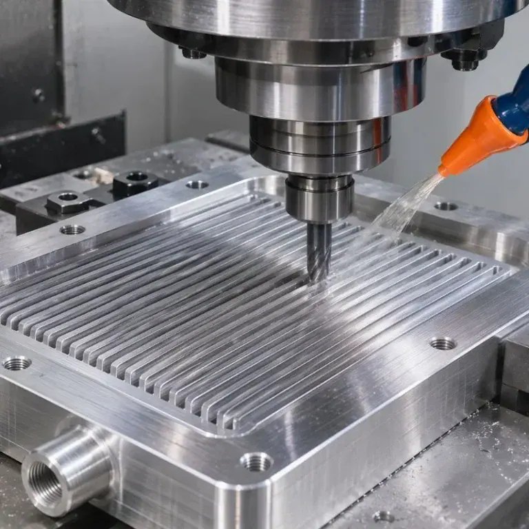
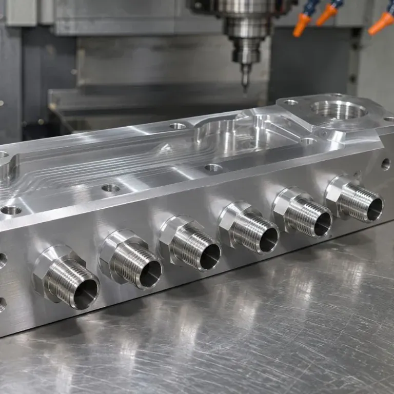
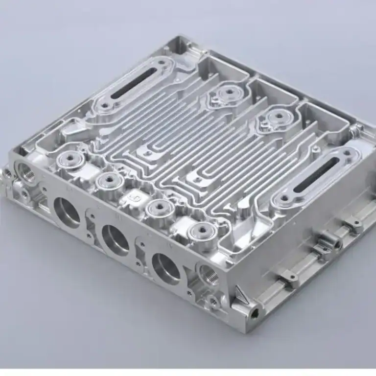
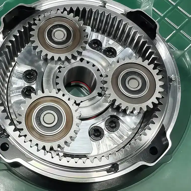
Industrial turbines operate under high rotational speeds, continuous friction, and elevated temperatures. Even a slight dimensional error in a shaft hole or a deviation in a blade’s curved profile can affect the performance of the entire machine. For equipment manufacturers, machining is not simply about reproducing the shapes shown in drawings. Components must also fit properly during assembly, maintain stable performance over time, and support convenient maintenance. CNC machining can handle complex surfaces, precision holes, and special fitting structures. It improves machining accuracy while helping maintain dimensional consistency across different production batches.
Which Industrial Turbine Components Require Precision CNC Machining?
An industrial turbine consists of many precision components, each with a different structure and function. Impellers require accurate surface profiles, shafts must withstand high-speed rotation, and housings and sealing rings need to meet installation and sealing requirements. Machining processes should be selected according to the actual purpose of each component. Besides external dimensions, manufacturers must also pay attention to hole positions, fitting clearances, and surface quality.

CNC Machining for Turbine Impellers and Blades
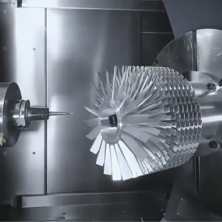
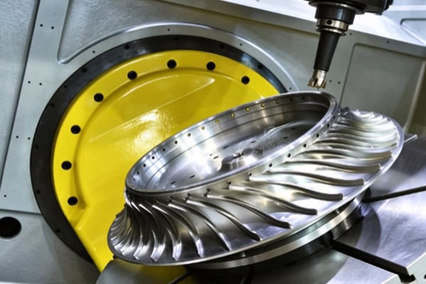
Impellers and blades directly affect airflow inside a turbine. Their curved profiles, blade thickness, and spacing between adjacent blades must be accurately controlled. Traditional machining methods may require repeated workpiece repositioning when dealing with complex surfaces, increasing the number of operations. Multi-axis CNC machining can follow 3D models to cut from different directions, producing complex profiles that closely match design specifications.
Several details require particular attention when machining these components:
- Surface profiles: Control blade curvature and transition areas to reduce profile deviations.
- Thin-wall structures: Arrange cutting sequences properly to prevent excessive local cutting forces from causing deformation.
- Surface finish: Reduce tool marks and burrs to minimize additional finishing work.
CNC Machining for Turbine Shafts and Sleeves
The shaft transmits power and operates under continuous rotation. Its journal dimensions and concentricity directly affect operating stability. If bearing mounting positions are inaccurate, the equipment may experience vibration or abnormal wear during operation. CNC turning is suitable for machining stepped shafts, shoulders, bearing seats, and sealing surfaces. Milling operations can also be used to produce keyways, flats, and other features.
Key machining requirements for shafts and sleeves include:
- Shaft journal diameters must meet drawing tolerances.
- Concentricity between critical shaft sections must remain consistent.
- Sleeve bore dimensions must match the outer diameter of the shaft.
- Fitting surfaces should be free of noticeable scratches and burrs.
Machining for Housings, Sealing Rings, and Connecting Seats
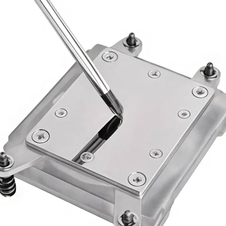
Although housings, sealing rings, and connecting seats do not always have the complex curved surfaces found on impellers, they often contain mounting holes, locating grooves, sealing grooves, and internal passages. Small deviations in hole positions can make assembly more difficult, while inaccurate sealing features may lead to fluid or gas leakage. CNC milling, drilling, and boring can produce these complex features with better control over mounting positions and connection dimensions.
What Precision Requirements Apply to Industrial Turbine Components?
Turbines operate at high speeds, so the clearances between components must be carefully controlled. Excessive dimensional deviations can affect assembly, while geometric errors may cause vibration, friction, and unstable operation. Different components have different precision requirements. Before production, manufacturers need to confirm critical dimensions, tolerance ranges, and actual assembly relationships. The following table outlines common machining priorities. Exact requirements should always follow the component drawings and operating conditions.
| Component | Key Machining Requirements | Impact on Equipment |
| Turbine blades | Surface profile and consistent thickness | Affects airflow and operating efficiency |
| Shaft | Concentricity and journal dimensions | Affects rotational stability |
| Sleeve | Bore dimensions and surface roughness | Affects fitting clearance and wear |
| Bearing housing | Hole position and mounting surface | Affects bearing positioning and support |
| Sealing ring | Roundness and sealing groove dimensions | Affects sealing performance |
How Can Blade Profiles and Thin-Wall Deformation Be Controlled?
Blade geometries are often irregular, and some sections have very thin walls. Cutting forces and clamping pressure can both cause slight deformation. Increasing cutting speed alone is not enough. The toolpath, cutting depth, and workpiece support method must also be considered. For components with demanding surface profiles, multi-axis machining can reduce repeated setups and allow the cutting tool to approach the workpiece from more suitable directions.
The following methods can help improve machining results:
- Remove material in stages instead of using an excessive cutting depth in one pass.
- Select suitable tools for curved surfaces to reduce localized cutting loads.
- Provide proper support and clamping for thin-wall sections.
- Control finishing allowances to reduce surface profile deviations.
How Can Shaft Concentricity and Dimensional Accuracy Be Maintained?
A turbine shaft usually contains bearing seats, sealing sections, and connecting sections. These features must maintain proper alignment along the shaft centerline. If different shaft sections are misaligned, additional friction may occur after assembly, accelerating wear on bearings and mating surfaces over time. Machining should minimize unnecessary setup changes and arrange roughing, semi-finishing, and finishing operations in a logical sequence. Appropriate finishing allowances should also be reserved for critical areas.
How Can Complex Holes and Sealing Grooves Be Machined Accurately?
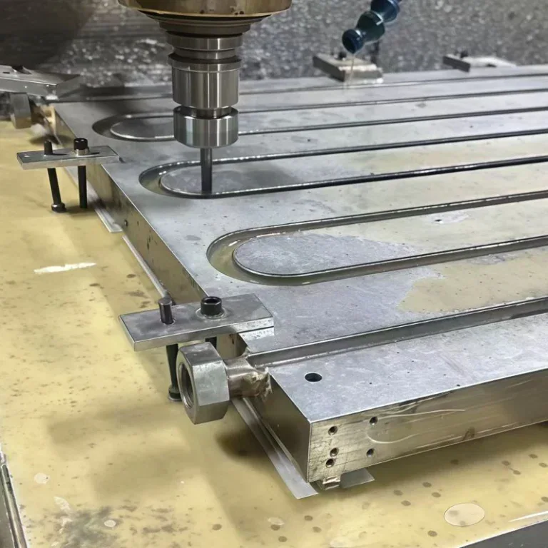
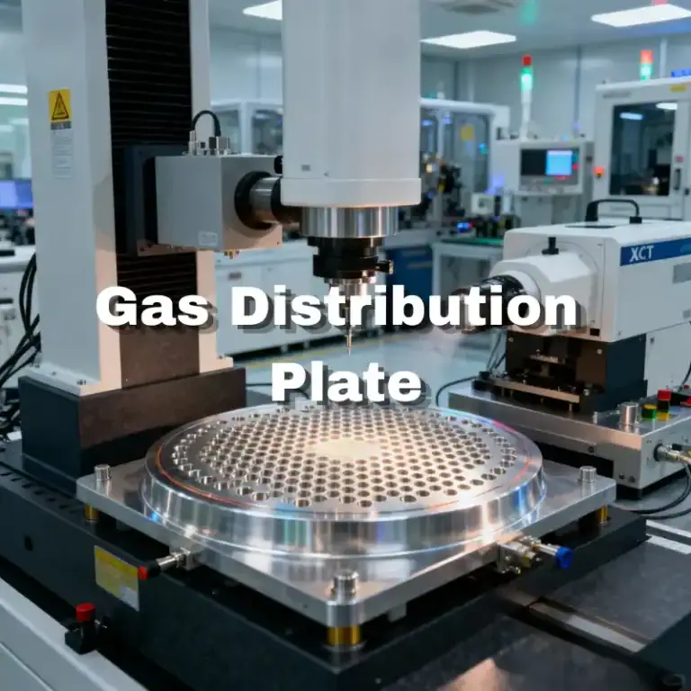
The holes and grooves on turbine housings and sealing rings are usually connected directly to other components. Their positional relationships are often just as important as individual dimensions. CNC drilling, boring, and slot milling use programmed tool movements to reduce errors caused by manual positioning. For internal passages and deep holes, tool accessibility and chip evacuation must also be considered in advance to prevent incomplete machining or trapped chips.
How Should Materials for Industrial Turbine Components Be Selected and Machined?
Turbine components must withstand different temperatures, loads, and operating environments. Choosing an unsuitable material can shorten service life even when the machined dimensions meet specifications. Common materials include stainless steel, alloy steel, aluminum alloy, and nickel-based heat-resistant alloys. Their hardness, toughness, and thermal conductivity vary, which means tool selection, cutting parameters, and cooling methods must be adjusted accordingly.
Machining Stainless Steel and Alloy Steel Components
Stainless steel is commonly used for connecting parts, housings, and certain shaft components, while alloy steel is often selected for structures requiring high strength and wear resistance. These materials meet the requirements of many industrial applications, but machining can involve tool wear and high cutting temperatures. Before production, the material grade and heat-treatment condition should be confirmed. Standard cutting parameters for ordinary steel should not be applied without adjustment.
- Stainless steel: Manage cutting heat and work hardening while ensuring effective chip removal.
- Alloy steel: Select tools according to material hardness and control cutting loads.
- Shaft components: Balance dimensional accuracy with surface finish to reduce wear on mating surfaces.
CNC Machining for Aluminum Alloy Turbine Structures
Aluminum alloy is lightweight and relatively easy to machine, making it suitable for certain housings, brackets, and auxiliary structures. Although it generally supports faster machining, thin-wall housings can deform under clamping pressure and cutting forces. Proper workpiece support is essential. Clamping force and machining sequences should also be controlled to prevent dimensional changes after the workpiece is released.
Machining Nickel-Based Heat-Resistant Alloy Components
Nickel-based heat-resistant alloys may be used in high-temperature turbine sections. These materials offer good strength and heat resistance at elevated temperatures, but they are also more difficult to machine. Cutting generates considerable heat, placing higher demands on tool heat resistance, machine rigidity, and cooling conditions. The material condition should be confirmed before selecting suitable tools and cutting parameters. This helps prevent excessive tool wear from affecting machining quality.
| Material Type | Typical Component Applications | CNC Machining Considerations |
| Stainless steel | Connectors, housings, shaft components | Cutting heat and tool wear |
| Alloy steel | Shafts and load-bearing components | Material hardness and dimensional stability |
| Aluminum alloy | Housings, brackets, auxiliary structures | Thin-wall deformation and clamping force |
| Nickel-based heat-resistant alloy | High-temperature components | Tool heat resistance and cutting parameters |
How Does CNC Machining Improve Industrial Turbine Component Production Efficiency?
Industrial turbine components often have complex structures, and some must be customized for specific equipment models. If different operations require repeated transfers and setups across multiple machines, production cycles become longer and positioning errors may increase. A well-planned CNC machining process can consolidate certain complex operations, reduce manual adjustments, and improve the transition from machining to final assembly.
Multi-Axis Machining Reduces Repeated Setups
Impellers, complex housings, and irregular connecting components often require cutting from different directions. Multi-axis CNC machines can complete more operations in a single setup, reducing errors caused by repeated positioning. For components with complex curved surfaces, optimized toolpaths can also shorten machining time and reduce manual intervention.
Digital Programs Improve Batch Production Efficiency
CNC programs can store toolpaths, tool information, and key machining parameters. When producing the same components again, manufacturers can reuse and optimize these programs based on actual production results. For industrial equipment companies that regularly purchase replacement or additional parts, this approach helps maintain dimensional consistency across batches and makes repeat orders easier to manage.
Custom Machining Supports Different Turbine Models
Different turbines vary in power, structure, and installation space, so their components are not always interchangeable. CNC machining allows production processes to be adjusted according to CAD drawings, 3D models, and technical specifications. It is suitable for both small-batch custom production and subsequent volume manufacturing. For components with special hole positions, complex curved surfaces, or non-standard connection structures, digital machining also helps reduce the production challenges associated with complex geometries.
Turbine component machining is not just about controlling dimensions and shapes. It directly affects equipment efficiency, service life, and maintenance costs. When selecting a machining service, buyers should look beyond price and consider material processing experience, complex component machining capabilities, and delivery schedules to avoid assembly problems after delivery. We provide precision CNC machining services for industrial equipment and can develop suitable machining solutions based on component drawings, materials, and technical requirements. Contact us to discuss your custom machining needs.