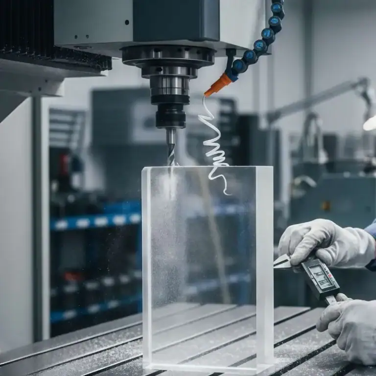
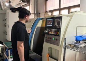
CNC turning is a classic subtractive manufacturing process.By rotating the workpiece at high speed and using the cutting tool to remove excess material on the workpiece surface, the product can finally reach its ideal shape, diameter and size.Drawing from my work experience, I will explain to you how CNC turning works, the machines involved, key operations, design considerations, and more.
What Does CNC Turning Means
CNC, stands for Computer Numerical Control, a system that automates machine tool movements with extreme precision using pre-programmed digital instructions. When I refer to CNC Turning, I’m specifically talking about the process where a Lathe spins the raw material(usually cylindrical)while a stationary cutting tool, directed by a CNC program, carves it into the desired shape.
What is CNC turning? In my daily operations, I use this process to produce high-precision components like shafts, bushings, and custom-threaded parts. The computer controls every axis of movement, feed rate, spindle speed, and toolpath. I regularly program tolerances as tight as ±0.01 mm, which is essential for applications in aerospace, medical, and automotive industries where fit and consistency matter. CNC turning isn’t just about shaping metal—it’s about automated consistency, repeatable quality, and high production efficiency.
How CNC Turning Works
When clients ask how CNC turning works, I explain it like this:
First loading a cylindrical bar—usually aluminum, steel, or brass—into the lathe’s chuck, securing it tightly. The spindle rotates the workpiece at speeds up to 4,000 RPM, which depending on material and desired surface finish.
Then, a stationary cutting tool—pre-programmed via G-code—moves precisely along the X and Z axes. These programmed toolpaths control feed rate (typically 0.05–0.3 mm/rev) and cutting depth, ensuring accurate geometry.
In simple terms,I load a cylindrical bar into the lathe, set the program, and the machine cuts the shape precisely—whether it’s a simple cylinder or a complex threaded shaft.
Key Differences From CNC Milling
In my experience, the main difference is this: CNC turning spins the workpiece, while CNC milling spins the cutting tool. When I machine cylindrical or round parts like shafts or bushings, turning is my choose. It’s faster and more accurate for such shapes.
Milling, however, is better for flat surfaces, pockets, or complex 3D contours. It allows multi-axis movement (up to 5-axis), which I use when a part has multiple faces or requires angular cuts.
For high-volume round parts, turning is more efficient—I’ve run jobs reaching 500 parts/hour on Swiss-type lathes. But for complex profiles, milling remains essential. Choosing the right process saves both time and tooling cost.
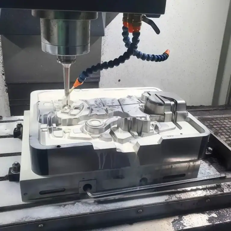
Process And Workflow
My CNC turning workflow begins with CAD modeling and G-code programming, optimized through CAM. I calibrate tools, run dry tests, and check chuck setup. During machining, I monitor for chatter. Final inspection uses calipers, micrometers, and CMMs. For aerospace, I verify ±0.005 mm tolerances and Ra ≤ 0.4 μm finish.
CAD Design & G-Code Programming
I begin by designing in CAD. Then I convert that design into G-code, which tells the lathe how to move. The CAM software I use optimizes cutting speed, tool changes, and toolpaths to minimize cycle time.
CNC Lathe Setup
Then I mount the proper tools in the turret and ensure the chuck holds the material securely. Proper setup includes tool calibration and dry runs to avoid any collisions or errors during actual cutting.
Material Loading And Toolpath Execution
Once the program is verified, I load the raw bar and let the lathe run. The toolpath executes as per the G-code—cutting, drilling, or threading. In whole process, I always monitor for vibration or chatter to maintain surface quality.
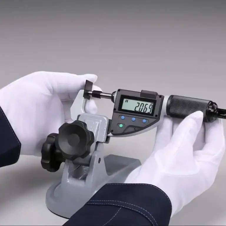
Quality Control And Final Part Inspection
After machining, I use micrometers, calipers, and CMMs to inspect critical dimensions. Surface finish is checked visually and by Ra tests. For tight-tolerance aerospace parts, every micron counts.
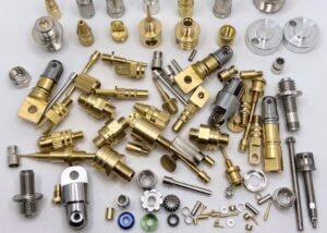
CNC Turning Operations
CNC turning includes various internal and external operations. I perform turning, facing, parting, and grooving with ±0.01 mm precision. Internally, I drill, bore, ream, thread, and knurl to ±0.02 mm accuracy. Taper and step turning enable efficient machining of complex shafts and cones. These capabilities ensure consistent delivery of both standard and custom geometries across industries.
External Operations: Turning, Facing, Parting, Grooving, Hard Turning
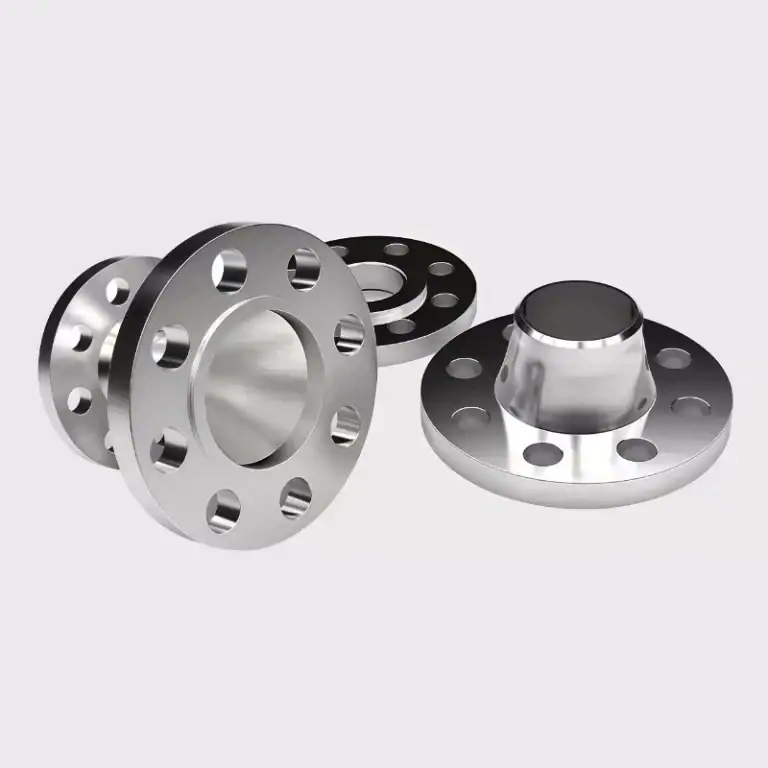
Turning: Turning is the primary method I use to reduce the outer diameter of rotating parts. It’s ideal for producing precision shafts, bushings, and rings, typically achieving dimensional tolerances within ±0.01 mm.
Facing: Facing is my go-to operation to create a flat, clean reference surface at the end of the part. I usually perform this first to ensure perpendicularity and prepare the stock for subsequent operations.
Parting :Parting, or Cut-Off, is used to separate finished components from the bar stock. I carefully control the feed rate and blade geometry to prevent burrs or deflection during separation.
Grooving: Grooving enables me to create recesses such as O-ring or snap-ring grooves. For example, I’ve machined grooves as narrow as 1.5 mm for retaining rings in hydraulic components.
Hard turning: Hard turning is a game changer. It allows me to machine hardened steels (up to 60 HRC) without switching to grinding. This reduces lead time and tooling cost, especially in finishing operations for tool steels or wear-resistant parts.
Internal Operations: Drilling, Boring, Reaming, Threading, Knurling
Drilling: Drilling is my starting point when creating internal features. I use both fixed and live tooling, depending on the machine setup. For example, I regularly drill deep center holes up to 100 mm for axles and custom threaded rods.
Boring: Boring allows me to refine and enlarge pre-drilled holes to achieve tight tolerances—often within ±0.01–0.02 mm. This is especially critical in parts requiring press-fit bearings or precise alignment.
Reaming: Reaming is my first choice when I need ultra-smooth hole finishes and accurate sizing, typically achieving surface roughness down to Ra 0.8 µm. It’s common in aerospace bushings and medical sleeves.
Threading: Threading is versatile—I machine both internal and external threads directly on the lathe, in metric, UNC, or custom pitches. I ensure proper lead and fit by adjusting feed rates and using dedicated threading inserts.
Knurling: Knurling adds functional texture. I’ve knurled aluminum knobs, stainless handles, and even medical grips where tactile control is key. Depending on the pattern—straight, diamond, or spiral—I can adjust the pressure and tool profile to match both aesthetics and functionality.
Taper Turning And Step Turning
Taper turning: Taper turning is critical when I need to machine conical profiles, such as nozzles, adaptors, or tapered pins. I typically set the tool path at a constant angular offset—say 5° or 10°—relative to the spindle axis. This allows me to achieve gradual transitions in diameter, with taper tolerances controlled within ±0.05 mm over lengths of 100 mm or more.
Step turning: Step turning, on the other hand, is ideal for components that require multiple distinct diameters along the same axis. I often use this method for drive shafts and spindle rods where bearings, collars, or pulleys must seat at specific positions. I program sequential cuts to reduce the diameter in precise increments—usually with step lengths ranging from 10 mm to 80 mm, and diameter variations up to ±0.02 mm depending on the fit required.
Both methods are essential in my workflow when producing high-functionality mechanical parts with complex dimensional requirements.
Types Of CNC Turning Machines
I select CNC lathes based on part size and job needs. Horizontal lathes handle most round parts efficiently. Vertical lathes offer better stability for heavy parts. Swiss-types are ideal for long, precise work. Multi-spindles cut cycle time for large batches. For flexibility, I use turning centers with live tooling, but still rely on conventional lathes for simple or prototype runs.
Horizontal CNC Lathes
Horizontal CNC lathes are my preferred machines for most standard cylindrical parts, such as shafts, sleeves, and bushings. Their horizontal orientation allows gravity to assist with chip evacuation, reducing tool interference and improving surface finish. With spindle speeds often exceeding 3,000 rpm and rapid tool change capabilities, I can achieve efficient cycle times even on medium-complexity parts. These machines strike a balance between precision, speed, and ease of operation for most production runs.
Vertical CNC Lathes
When machining large or heavy components like pump housings or valve bodies, I rely on vertical CNC lathes for their superior stability. Gravity helps center and support the workpiece, minimizing deflection and vibration. This setup is especially useful for parts exceeding 500 mm in diameter or weighing over 100 kg. However, chip evacuation becomes more challenging in vertical setups, so I always implement controlled coolant flow and periodic stops to manage swarf buildup effectively.
Swiss-Type & Multi-Spindle Lathes
Swiss-Type: Swiss-Type lathes are my prime choice for producing long, slender parts—such as bone screws or sensor pins. Thanks to the guide bushing, the workpiece is supported close to the cutting tool, minimizing deflection and improving surface finish.
Multi-Spindle: For high-volume production, I turn to multi-spindle machines. With up to 6 or 8 spindles working in parallel, I’ve cut cycle times by over 50% in automotive projects, making them ideal for mass production of small, repeatable components.
Turning Centers VS. Conventional CNC Lathes
Turning centers offer multifunctionality—besides turning, I can also perform drilling, milling, and even tapping in a single setup using live tooling. This integration boosts efficiency, especially for complex parts.
On the other hand, conventional CNC lathes are simpler and focus purely on turning operations. I still rely on them for straightforward parts or prototype runs where speed and setup simplicity are more important than versatility.
Machine Components & Software
In CNC turning, machine components and software drive precision. I rely on the headstock, spindle, and tailstock for support, with the bed and carriage ensuring stability. The turret carries multiple tools, and I choose chucks or collets based on the part. I use Fanuc or Siemens controllers, program with Fusion 360, and simplify basic tasks using Manual Guide i or iHMI.
Headstock, Tailstock, Spindle, Bed, Carriage
Headstock & Spindle:The headstock is the core power unit of my CNC lathe. It houses the main spindle and motor, delivering rotational speeds from 100 up to 4,000 RPM depending on the material and job. A stable spindle ensures consistent concentricity, which is critical when I’m machining precision parts with tolerances as tight as ±0.01 mm.
Tailstock:When working on long shafts or slender components, I use the tailstock. It supports the free end of the part and minimizes deflection under cutting forces. This is especially important for parts over 200 mm in length, where even minor bending can affect dimensional accuracy.
Bed:The bed provides the structural foundation of the lathe. I check for casting quality and rigidity, because a stable bed minimizes vibration. For example, in high-speed finishing operations, excess vibration can increase surface roughness beyond 3.2 μm Ra—which is unacceptable for many of my aerospace clients.
Carriage:The carriage holds the tool turret and travels along the X and Z axes. It’s responsible for delivering the tool to the exact programmed position. I regularly inspect its linear guideways and ball screws to ensure I maintain repeatability within ±0.005 mm over long production runs.
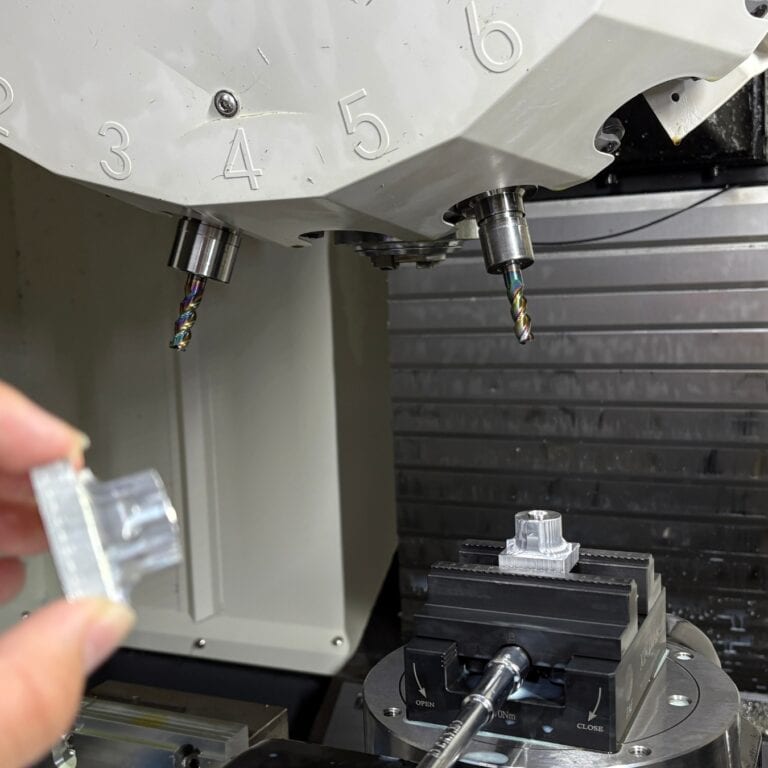
Tool Turret, Chuck & Collet
Turret: The turret is where I mount all the tools needed for a machining cycle. On my 12-station turret, I pre-load everything from turning tools to threading inserts. This setup allows me to automate complex multi-step operations without manual intervention. Tool indexing time is typically under 0.5 seconds, which keeps cycle time efficient in high-volume runs.
Chuck: For standard cylindrical workpieces above 12 mm in diameter, I use a 3-jaw hydraulic chuck. It offers strong clamping force and quick changeovers. Accuracy usually holds within 0.03 mm TIR, which is suitable for most general-purpose applications.
Collets: When I machine small or high-precision parts—especially under 10 mm OD—I switch to a collet system. Collets provide superior concentricity control, often within 0.01 mm. I rely on this setup when making medical components or parts requiring ultra-tight tolerances across long batches.
Control Panel & CNC Software
CNC Control Panel: I primarily work with Fanuc and Siemens control systems, which dominate industrial CNC turning. These panels allow me to upload and edit G-code, adjust feed rates, and monitor real-time machining cycles. For example, I can fine-tune spindle speed or tool offsets mid-run without stopping production—critical when maintaining ±0.01 mm tolerances.
G-code Programming: G-code is the language of the machine. I write and optimize it to dictate every movement—X, Z axes, spindle RPM, and tool change commands. It ensures each pass is consistent, which is essential for mass production.
CAM Software Integration: For complex parts or 3D profiles, I rely on Fusion 360 or Mastercam to generate accurate toolpaths. These platforms convert my CAD designs into clean, collision-free machining instructions. On multi-op jobs, using CAM reduces setup time by over 30% and improves repeatability across batches.
Manual Guide i & iHMI (advanced)
AdManual Guide i (Fanuc):I often use Manual Guide i when working on simpler parts or training new operators. It’s a conversational programming interface that allows me to create turning cycles without writing full G-code. For instance, I can program a facing and turning operation just by inputting dimensions and parameters—cutting cycle preparation time by up to 40% for standard jobs.
IHMI (Intelligent Human-Machine Interface):
The iHMI system integrates visualization, maintenance alerts, and production monitoring into one smart dashboard. I use it to track spindle load, cycle time, and tool wear in real-time. On longer production runs, this helps me prevent downtime by scheduling predictive maintenance before issues arise.
With these advanced controls, I streamline prototyping and short-run jobs. Even less experienced operators can handle basic part programs using templates or guided cycles. That reduces operator error and shortens the learning curve significantly.
Turning Parameters & Tooling
In CNC turning, I fine-tune three core parameters—feed rate, cutting speed, and depth of cut—based on material and surface finish needs. For example, I cut aluminum at 300 m/min and steel at 100 m/min. I use boring bars, grooving tools, thread cutters, and knurling tools to achieve precision. Each tool and setting directly affects cycle time, tolerance (±0.01 mm), and surface roughness (Ra <0.4μm), so I adjust them carefully for efficiency and accuracy.
Feed Rate, Cutting Speed, Depth of Cut
Feed Rate (mm/rev): For steel, I typically use 0.1–0.3 mm/rev. For plastics, up to 0.5 mm/rev. Higher feed improves material removal rate but can harm surface finish.
Cutting Speed (m/min): Varies by material. For example, aluminum might be cut at 200–400 m/min, while stainless steel needs 60–120 m/min.
Depth of Cut (mm): Roughing might use 1–3 mm, finishing cuts are under 0.5 mm. I adjust these to prevent tool chatter or thermal issues.
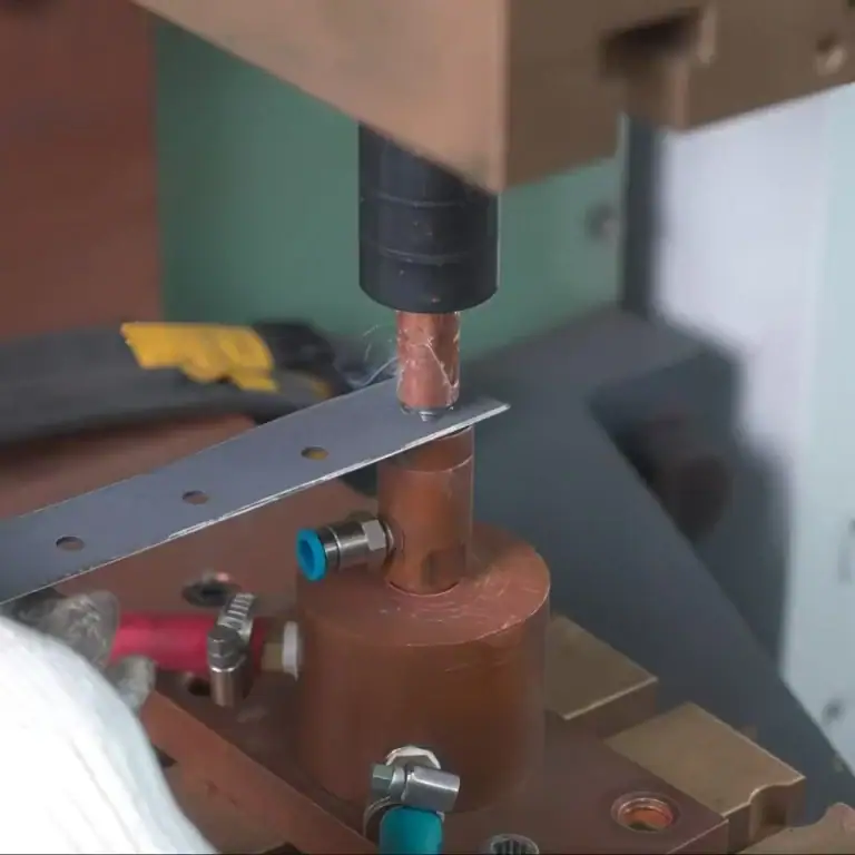
Tool Types: Boring Bars, Grooving Tools, Thread Cutters, Knurling Tools
Boring Bars: For internal finishing, I rely on vibration-dampened carbide bars.
Grooving Tools: I choose insert widths based on groove depth, a 3 mm-wide insert is standard for retaining ring grooves.
Thread Cutters: For ISO metric threads, I use indexable threading tools and verify with pitch gauges.
Knurling Tools: There are form-type and cut-type, I prefer cut-type for clean diamond patterns in brass and aluminum.
Materials Suitable For CNC Turning
Material choice defines precision and efficiency. I’ve machined aluminum, titanium, Inconel, ABS, and PEEK. Aluminum supports fast cutting, while tougher metals and plastics need thermal control and special tooling. Each requires custom speeds and cooling to hold ±0.01–0.03 mm tolerances.Metals: Aluminum, Steel, Brass, Titanium
| Material Type | Example Grades | Machining Characteristics | Typical Applications |
| Aluminum | 6061, 7075 | High-speed cutting (300+ m/min), excellent machinability | Aerospace brackets, enclosures |
| Steel | 1018, 4140, SS304 | Strong, requires reduced speeds and coolant to protect tools | Structural parts, tools |
| Brass | C360 | Very low friction, clean chip removal | Fittings, electrical connectors |
| Titanium | Ti-6Al-4V | Tough, heat-resistant, low feed and coated tools needed | Aerospace and medical components |
| Plastics | ABS | Machined at low RPM to avoid melting | Prototype enclosures |
| Nylon (PA6, PA66) | Warps easily; requires heat control and chip clearance | Gears, bushings | |
| PEEK | Tolerances ±0.03 mm, excellent thermal stability | Aerospace insulators | |
| Composites & Alloys | G10, Inconel | Require diamond-coated tools; frequent tool changes due to wear | High-temp or high-strength parts |
Application Areas In Various Industries
CNC turning is applied across industries—from medical bone screws to aerospace connectors. It’s also key in automotive, energy, and electronics. I deliver high-precision parts that meet strict performance and material standards.
| Industry | Common Parts Machined | Material Choices | Technical Requirements & Notes |
| Automotive | Axles, bushings, engine components | Carbon steel, aluminum alloys | High-volume consistency, cost-efficiency, ±0.02 mm tolerance |
| Aerospace | Landing gear pins, actuator parts, fasteners | Titanium, 7075 aluminum | Lightweight, high strength, requires certifications and QC |
| Medical | Orthopedic implants, dental abutments, tools | 17-4PH stainless steel, PEEK | Surface finish below Ra 0.8 μm, biocompatibility |
| Electronics | Connector pins, RF shields, threaded spacers | Brass, aluminum | Often combines threading and slotting in a single cycle |
| Industrial Equipment | Valve bodies, shafts, coupling parts | Hardened steel, alloy steel | Hard turning after heat treatment for wear resistance |
Advantages And Limitations Of CNC Turning
CNC turning offers high precision (±0.01 mm), fast production—up to 60% quicker than manual methods—and excellent safety. However, it’s limited to rotational parts and can be costly for low-volume jobs due to complex setup requirements.
| Category | Aspect | Details |
| Advantages | Accuracy | I routinely achieve ±0.01 mm tolerances and maintain consistency over 1,000+ parts with tool wear monitoring. |
| Speed | Compared to manual lathes, CNC turning reduces production time by 40–60%. | |
| Safety | Operators stay clear of cutting zones; built-in interlocks prevent accidents. | |
| Limitations | Geometry Constraints | Since the workpiece must rotate, irregular shapes (e.g., flat plates) are not suitable—milling is preferred instead. |
| Setup Cost | Low-volume jobs with complex tooling setups may be costly; one prototype thread ring required $300 just in setup. |
Design Considerations
In every CNC turning project I handle, success begins with thoughtful design. Even the most advanced machine can’t compensate for poorly engineered parts. Below are key aspects I always evaluate before quoting or programming.
Suitable Part Geometries
Rotational symmetry: CNC turning is ideal for cylindrical, conical, and threaded shapes. For example, shafts, bushings, and flanges are classic examples.
Avoid square features: Flat surfaces or square corners are better suited for milling. If needed, I integrate secondary processes.
Tool access: Long overhangs or deep recesses can cause chatter or tool deflection.
Tolerancing And Surface Finish
Tolerancing: I work to ISO 2768-mK for general turning. For precision parts, ±0.01 mm is standard, but I’ve done ±0.005 mm in controlled environments.
Surface Finish: A typical turned finish is Ra 1.6 μm, but I can achieve Ra 0.4 μm or better with proper inserts and speeds. Medical and optical parts often require polishing after turning.
Common Design Errors
Undercuts without relief grooves make parting impossible.
Overtight tolerances drive up costs unnecessarily—like asking for ±0.005 mm on a plastic spacer.
Sharp corners increase tool wear, I always suggest chamfers or radii.
CNC Turning VS Other Methods
When I guide clients on process selection, I compare CNC turning with milling, casting, molding, and grinding. Turning excels at cylindrical parts and high-speed production, while milling suits complex shapes. For large plastic batches, injection molding is better, for tight tolerances, turning plus grinding works best. I often combine turning with milling to balance precision and efficiency.
Comparison With CNC Milling
CNC turning rotates the workpiece, while milling rotates the cutting tool around a stationary part. I prefer turning for high-speed production of symmetrical parts like shafts, rods, and tubes—especially when tolerances within ±0.01 mm are required. For components with complex pockets or non-cylindrical features, milling offers greater flexibility.
In one recent case, a client needed a cylindrical part with lateral milled slots. I combined CNC turning with 3-axis milling, which reduced cycle time by 30% while ensuring dimensional accuracy.
Alternatives: Casting, Injection Molding, Grinding
Casting: Best for high-volume parts where tight tolerances aren’t critical. I’ve replaced castings with turned parts for better precision.
Injection Molding: Excellent for plastic parts above 5,000 pcs. For anything lower, CNC turning is more cost-effective.
Grinding: Used after turning for ultra-precise finishes below Ra 0.4 μm, like in hardened shafts.
Cost and Productivity Aspects
When I evaluate CNC turning costs, I balance machine rates (\$30–\$100/hr), tooling expenses (\$10–\$50 per insert), and cycle times. A simple part may take 2–3 minutes, but with optimization or multi-spindle machines, output doubles. For 500 aluminum parts, I’ve cut unit cost by over 40% through bar feeding and toolpath tweaks. Batching always improves ROI.
Machine Cost & Tooling
Machine hourly rate: Varies between $30–$100/hour depending on the machine type and operator expertise.
Tooling costs: Carbide inserts can cost $10–$50 each. Specialized tools for threading or knurling add up quickly in low-volume jobs.
Cycle Time & Volume
A typical brass bushing (Ø30 × 20 mm) takes 2–3 minutes to complete. With multi-spindle lathes, I can halve that.
High-volume production (1,000+ pcs) justifies fixturing and tooling costs. For low volumes, I simplify setups to avoid waste.
ROI Considerations
For a run of 500 turned aluminum housings, we reduced unit cost from $6.50 to $3.80 by optimizing toolpaths and using bar feeding.
I always recommend batching orders when possible to amortize setup time and tooling investment.
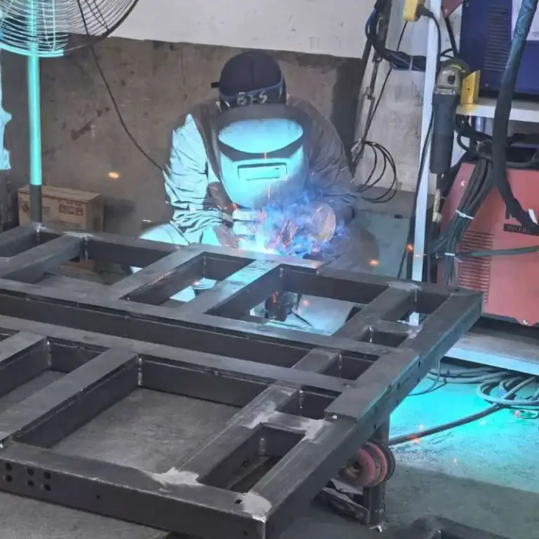
Safety, Maintenance & Sustainability
I prioritize operator safety with LOTO procedures, chip conveyors, and tool breakage detection. Routine maintenance—daily, weekly, and monthly—is key to preventing vibration and accuracy loss. Environmentally, I use biodegradable coolants, mist collectors, and recycle metal chips like aluminum, aligning CNC turning operations with modern sustainability goals.
Best Practices & Operator Safety
I ensure all operators follow lockout/tagout (LOTO) protocols.
We use automatic chip conveyors to avoid manual handling injuries.
Regular tool breakage detection systems prevent accidents caused by flying inserts.
Routine Maintenance
Daily: Clean chips, check fluid levels.
Weekly: Inspect spindle belts, check turret alignment.
Monthly: Calibrate tool probe, check backlash.
Neglecting maintenance leads to vibration, accuracy loss, and costly downtime.
Environmental Considerations
We use water-soluble coolants that are biodegradable and safe to dispose with proper filtration.
Our machines are equipped with mist collectors and chip recycling systems—aluminum chips are collected and sold back to suppliers.
How To Choose The Right CNC Turning Service
When helping clients select a CNC turning partner, I focus on more than part quality. I guide them to evaluate technical capabilities, verify certifications like ISO 9001 or AS9100, and assess lead times for various quantities. Choosing the right supplier means ensuring precision, reliability, and consistent delivery at scale.
Evaluation Criteria
Technical capability: Can the shop meet tolerances, surface finish, and material requirements?
Certifications: For aerospace or medical, ISO 9001 or AS9100 is non-negotiable.
Lead times: Ask about setup time and average turnaround for 100, 500, and 1000 parts.
FAQs
What is a CNC turning job?
A CNC turning job involves machining cylindrical parts using a lathe controlled by G-code. I program the toolpath, set feed rates (e.g., 0.2 mm/rev), and monitor tolerances—typically within ±0.01 mm. It’s ideal for shafts, bushings, and threaded parts in medium to high volumes.
What is the difference between CNC milling and CNC turning?
The main difference lies in motion: CNC turning rotates the workpiece while the tool stays still, CNC milling rotates the tool around a fixed part. I use turning for round parts like pins or shafts, while milling suits flat or complex geometries with multi-axis control.
What are the advantages of CNC turning?
CNC turning offers high precision, speed, and repeatability. It can achieve tolerances of ±0.01 mm and surface finishes below Ra 0.4 µm. It’s especially efficient for cylindrical parts and high-volume production. Automation reduces labor, and cycle times can be under 30 seconds per part in optimized setups.
How many types of CNC turning are there?
There are several types of CNC turning I commonly use: standard horizontal lathes, vertical lathes for heavy parts, Swiss-type lathes for long, precise components, and multi-spindle machines for mass production. Each type serves specific needs, depending on part geometry, tolerance (often ±0.01 mm), and volume.
How accurate is a CNC turning machine?
CNC turning machines are highly precise. In my projects, I regularly achieve tolerances of ±0.01 mm, and for high-precision parts like shafts or bushings, I can tighten that to ±0.005 mm. Accuracy depends on machine condition, tooling, and material stability.
What is the Feed function of CNC on turning process?
In CNC turning, the feed function controls how fast the tool advances per spindle revolution. I usually set it between 0.1–0.3 mm/rev for metals, depending on surface finish and material type. Precise feed rates help balance tool life, surface quality, and material removal efficiency.
Conclusion
CNC turning remains a cornerstone of precision manufacturing—especially when efficiency, repeatability, and tight tolerances matter most. From defining its principles to navigating tooling, machine types, material selection, and real-world costs, I’ve guided clients across automotive, aerospace, and medical sectors through the nuances of the process. Whether you’re designing a simple bushing or a complex stepped shaft, understanding how turning works empowers better decisions, fewer revisions, and ultimately, stronger parts. If you’re planning your next project, CNC turning might just be the solution that keeps your production fast, accurate, and scalable.