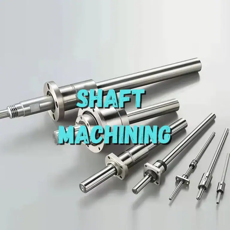
CNC turning concentricity is an important quality requirement in precision shaft machining, especially for transmission shafts, stepped shafts, bushings, precision sleeves, connectors, and other rotational components. When a part contains multiple concentric outer diameters, internal bores, shoulders, or precision mating surfaces, controlling individual dimensional tolerances alone may not be sufficient to ensure proper assembly and operating performance. If concentricity or radial runout exceeds the specified tolerance, the component may experience vibration, eccentric rotation, uneven wear, or assembly difficulties during operation. CNC turning can improve concentricity and batch consistency through stable spindle performance, appropriate workholding, consistent machining datums, accurate tool compensation, and in-process inspection. TiRapid provides CNC turning services for shafts, sleeves, and other rotational components, with precision machining, DFM support, and quality inspection capabilities.
Why Does CNC Turning Concentricity Affect Precision Part Performance?
For shaft components, concentricity is not an isolated dimensional requirement. It is closely related to rotational accuracy, assembly fit, bearing performance, and component service life. When a part contains multiple shaft diameters, internal bores, threaded sections, and positioning shoulders, the relationship between their center axes can directly affect the final performance of the assembly. Precision rotating components used in motors, gearboxes, automation equipment, automotive transmission systems, and precision machinery must maintain stable rotation. Significant misalignment between different shaft sections can create additional radial forces and vibration, potentially affecting the operating stability of the entire system. For precision CNC turning, concentricity control needs to be considered throughout part design, workholding, machining sequence, and final inspection rather than relying only on final inspection to identify problems.
Concentricity Is Closely Related to Radial Runout
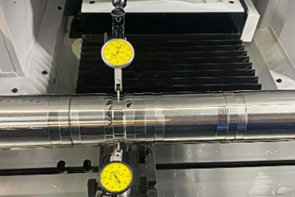
Engineering drawings may specify concentricity, circular runout, or total runout depending on the functional requirements of the component. For rotating parts, radial runout provides a practical indication of how much a machined surface deviates from the reference axis during rotation, while concentricity describes the relationship between the center of a controlled feature and the datum axis. During production, machining multiple shaft diameters in a single setup can reduce repositioning errors and help maintain the relationship between different features. Precision CNC turning suppliers may use dial indicators, V-blocks, dedicated gauges, or CMM equipment for inspection depending on the drawing requirements and part geometry.
Shaft Components Require Careful Concentricity Control
Shaft components often contain several machining zones, including bearing seats, sealing surfaces, positioning shoulders, threaded sections, and connection ends. When these areas must rotate together or mate precisely with other components, controlling each individual diameter is not enough to guarantee assembly performance. For example, two bearing seats on a shaft may both meet their dimensional tolerances while still having significant axial misalignment between them. After assembly, this condition can cause increased rotational resistance, vibration, or premature wear. For precision transmission shafts, robotic joint shafts, automation equipment shafts, and precision mechanical shafts, critical datums and mating areas should be defined during the design stage and maintained consistently throughout the CNC turning process.
What Factors Affect Concentricity in CNC Turning?
CNC turning concentricity is influenced by machine condition, tooling, workpiece characteristics, workholding, cutting parameters, and thermal changes. A significant variation in any of these factors can increase axial or radial deviation in precision shaft components. TiRapid’s turning information also identifies spindle accuracy, machine rigidity, clamping methods, tool condition, and temperature changes as important factors affecting turning accuracy.
Spindle Accuracy Determines Rotational Stability
The CNC lathe spindle rotates the workpiece during machining, so spindle accuracy directly affects the cutting condition. If the spindle has excessive runout, bearing wear, or accuracy degradation after prolonged operation, even an accurately programmed tool path may fail to produce stable concentricity. Precision CNC turning requires regular inspection of spindle condition, turret positioning accuracy, and machine geometry, followed by appropriate maintenance and calibration based on machine usage. A stable machine foundation helps reduce dimensional drift during batch production and improves repeatability between different production runs.
Workholding Determines Datum Stability
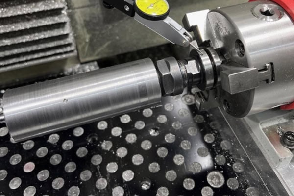
Workholding is a critical factor affecting CNC turning concentricity. Standard three-jaw chucks are suitable for many conventional rotational components, but precision stepped shafts, thin-wall sleeves, and long shafts may require more stable clamping methods. Insufficient gripping length, uneven clamping force, or burrs on the locating surface can cause workpiece eccentricity. For long shaft components, tailstock support, steady rests, or other auxiliary supports can reduce vibration and deformation during machining. TiRapid’s precision machining guidance also emphasizes the importance of tailstock support, steady rests, and reduced overhang when machining long shaft components.
Tool Wear Can Cause Dimensional and Geometric Errors
As a cutting tool is used over time, wear gradually changes the actual cutting condition. Minor changes during rough machining may not immediately affect functionality, but during finishing operations, changes in tool nose radius, cutting edge condition, or tool position can lead to diameter deviations, surface finish changes, and geometric accuracy variations. For batch CNC turning production, manufacturers can establish tool-life management procedures, perform first-article inspection, monitor critical dimensions during production, and replace or compensate tools before they reach their wear limits. This helps reduce consistency problems across large production batches.
How Can CNC Turning Processes Control Concentricity?
Controlling concentricity in precision turning requires more than simply using a high-accuracy machine. A suitable machining process must also define the locating datum, workholding method, roughing and finishing sequence, and inspection points according to the part geometry. The more stable the machining process and the fewer datum changes involved, the easier it is to maintain concentric relationships between different features.
Minimize Repeated Workholding
When a component contains several features that must remain concentric, completing the critical features in a single setup whenever possible can reduce positioning errors. Repeated workholding introduces new locating errors, and every repositioning operation can change the workpiece axis. For shaft components, the primary datum can be machined first and then used to complete other critical diameters, faces, and bores. This approach reduces accumulated positioning errors and improves the consistency of precision CNC turned parts.
Establish a Proper Roughing and Finishing Sequence
Rough machining primarily removes excess material efficiently, while finishing operations establish the final dimensions and geometric accuracy. If the final dimensions are produced in a single operation without sufficient process control, internal stress, cutting heat, and tool loads may cause dimensional changes. A suitable process normally leaves an appropriate finishing allowance after roughing. The workpiece can then reach a more stable condition before critical diameters, bores, and faces are finished. For precision shafts, staged machining can also be used according to the material characteristics to make the final finishing process more stable.
Optimize Support for Long Shaft Components
Long and slender shafts may lack sufficient rigidity, causing bending or vibration during cutting. These conditions can affect diameter accuracy, roundness, and concentricity. Tailstock support, steady rests, or other auxiliary supports can reduce the effective overhang and limit deformation caused by cutting forces. For longer shafts, engineers should also consider tool position, machining direction, and cutting parameters during process planning. The higher the length-to-diameter ratio, the more important it becomes to evaluate support and vibration control during the quotation and engineering stages.
How Should Concentricity Be Inspected in Precision CNC Turning?
After machining, the inspection method should be selected according to the engineering drawing and the functional requirements of the component. Common inspection methods include dial indicator testing, V-block inspection, dedicated gauges, and coordinate measuring machines. Standard mechanical components may use economical inspection methods according to their tolerance requirements, while high-precision shafts, medical components, aerospace parts, and critical transmission components may require more comprehensive dimensional and geometric inspection. Inspection methods should always be linked to the drawing datums and functional requirements so that the measurement results accurately represent actual component performance.
Dial Indicators Are Suitable for Quick Radial Runout Inspection
Dial indicators are commonly used on the shop floor for checking rotational runout. After the workpiece is securely positioned, the indicator tip is placed against the surface being inspected. The workpiece is then rotated slowly while the indicator movement is observed to determine the runout condition. This method is simple and efficient for first-article checks, in-process inspection, and quick pre-shipment verification. However, the measurement result can be affected by workholding, datum selection, and inspection position. For strict geometric tolerance requirements, more precise measurement equipment may also be required.
CMMs Are Suitable for Complex Geometric Inspection
A coordinate measuring machine can digitally measure multiple dimensions and geometric features while establishing a datum system according to the engineering drawing. For precision turned parts with multiple shaft diameters, internal bores, faces, and complex positioning features, CMM inspection can provide more comprehensive measurement data. Critical dimensions, positional relationships, roundness, and concentricity-related features can be verified, and inspection reports can be generated. Precision machining suppliers may provide first-article inspection or quality reports according to customer requirements, helping engineering and procurement teams verify that the parts meet the specified design requirements.
Inspection Requirements Should Match Part Function
Not every shaft component requires extremely tight concentricity tolerances. If a component does not depend on very high rotational accuracy, unnecessarily tight tolerances can increase machining, inspection, and delivery costs. Bearing seats, sealing surfaces, and precision rotating areas may require tighter control based on actual assembly conditions. Engineering drawings should clearly identify the dimensions and geometric characteristics that directly affect function, allowing the machining supplier to evaluate the manufacturing process and quotation accurately. Critical tolerances should be established according to actual application requirements rather than applying extremely tight tolerances uniformly to every feature.
How to Choose a Precision CNC Turning Manufacturer for Shaft Components?
For projects requiring high concentricity, repeatability, and stable batch production, the supplier’s engineering and quality management capabilities are just as important as machine specifications. When sourcing precision CNC turned parts, procurement teams can evaluate machining equipment, process experience, inspection capabilities, DFM support, prototype validation, and production capacity. TiRapid provides CNC turning, DFM support, and precision machining for materials including aluminum alloys, stainless steel, titanium alloys, brass, copper, and engineering plastics. Its published CNC turning information indicates specified tolerances can reach approximately ±0.005 mm and typical surface roughness can reach Ra 0.6, depending on part geometry, material, and drawing requirements.
Confirm Precision Shaft Machining Capabilities
Before placing an order, provide the component drawing to the CNC machining supplier so the engineering team can review critical shaft diameters, internal bores, concentricity, runout, threads, and surface treatment requirements. For long shafts, thin-wall sleeves, small-diameter shafts, or complex stepped shafts, the supplier should also confirm the available machining range and support method.
- Precision CNC turning equipment
- Capability for critical shaft diameters and internal bores
- Experience with long shaft machining
- Контроль соосности и биения
- First-article inspection capability
- Support for prototype through production quantities
Clear technical confirmation allows procurement teams to evaluate manufacturability before production and reduces the risk of process changes after production has started.
Provide Complete Engineering Drawings and 3D CAD Models
A precision CNC turning quotation should not rely only on a basic 3D model. The 2D engineering drawing should clearly specify critical dimensions, material, surface roughness, tolerances, thread standards, and geometric requirements. A 3D CAD model helps engineers understand the complete component geometry. Providing both files can improve the efficiency of the DFM review.
- STEP or other 3D CAD models
- PDF or DWG engineering drawings
- Материал сорта
- Критические допуски размеров
- Требования к соосности или биению
- Шероховатость поверхности
- Требования к обработке поверхности
- Количество заказа
- Требуемый график доставки
The more complete the technical information, the easier it is for engineers to determine the machining process, tooling configuration, inspection plan, and production schedule, which also supports a more accurate CNC turning quotation.
Produce Prototypes Before Moving to Batch Production
For high-precision shaft components, entering mass production immediately may increase process adjustment risks. CNC turning prototypes allow manufacturers to verify material selection, workholding, tooling, machining sequence, and inspection procedures before production quantities increase. Based on prototype inspection results, the machining process can then be adjusted and standardized. Once the prototype is approved, the supplier can move into batch production with a more stable manufacturing process, reducing the likelihood of dimensional deviations across production quantities.
For projects requiring precision shafts, bushings, connectors, and other rotational components, procurement teams can provide engineering drawings, 3D models, material specifications, critical tolerances, concentricity requirements, quantities, and delivery schedules during the quotation stage. TiRapid provides CNC turning and DFM support from prototype machining through production manufacturing and can evaluate manufacturability according to the specific geometry and requirements of each component.