Prototyping is more than making a model—it’s a structured workflow that guides a product from concept to scalable production. Each of the prototype stages helps reduce risk, validate assumptions, and refine the design before major tooling investment. This guide outlines the five key prototype stages, the core tools, and common pitfalls, giving you a clear path from idea to manufacturing.
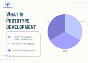
What Is Prototype Development
Prototype development is the process of turning ideas into testable models to validate functionality, appearance, manufacturability, and market acceptance. Through staged iterations, teams can reduce risk, uncover issues early, and ensure the final product meets real engineering and user needs.
The Role Of Prototypes In Product Development
Reducing technical uncertainty
During Alpha builds, I often use CNC or 3D printing to verify assembly fit, load strength, and tolerance behavior—catching issues long before tooling.
Validating user experience
Looks-like prototypes reveal ergonomic flaws early. In one handheld device project, the initial design caused accidental button triggers. A physical mockup helped us reposition elements before engineering began.
Supporting business and investment decisions
High-fidelity prototypes help executives and investors understand value, accelerating tooling approval and supply chain planning.
The Value Of Prototyping
Risk Reduction
Industry studies show that fixing a design issue after mass production is 10–100× more expensive than discovering it during prototyping.
Design Validation
Works-like prototypes test real conditions: thermal performance, motor torque, structural integrity, or sensor accuracy.
Cost Efficiency
With rapid iteration, I often help teams finalize engineering within 3–5 cycles, preventing mold rework and shortening development time.
Common Prototype Types
The types of prototypes developed vary depending on the stage of prototype development:
Looks-like Prototype
Validates appearance, form factor, and UX layout
Typically built via SLA, clay, or hand-crafted models
Useful for presentations and early marketing
Works-like Prototype
Verifies structure, mechanics, electronics
Often built with SLS + CNC for strength + precision
Goal: ensure core functions work reliably
Test Prototype (Beta / EVT / DVT)
For user testing, reliability tests, environmental simulations
Multiple units required for statistical validation
Uses near-production materials and processes
Pre-production Prototype (PVT)
Small batch run (5–10%)
Built with full-scale production processes such as injection molding
Validates assembly, QC, packaging, and logistics readiness
Five Main Stages Of Prototype Development
Prototype development is a structured process that validates product feasibility from concept to production. Each of the five prototype stages reduces risk, optimizes design, and ensures the product meets real user and engineering requirements. Mastering these stages accelerates the path from idea to manufacturing.
Stage 1 – Define The Vision & Identify The Problem
Understand Market Needs and User Pain Points
Before any design work, I investigate user behavior and failure scenarios. Great products solve the right problem—not all problems. In an outdoor equipment project, users struggled with cold-weather operation, so “cold usability” became our core design priority.
Set Product Goals and Feature Requirements
I prefer a “subtraction strategy,” focusing on the key feature first to avoid overcomplicated early prototypes that slow development.
Outputs
Concept sketches
Vision statement
Requirement list (early PRD)
Stage 2 – Concept Development & Feasibility (POC)
Brainstorming & Concept Screening
I use sketches, storyboards, and quick CAD to explore solutions, then filter options based on cost, technical feasibility, and risk.
Build Early Proof-of-Concept Models
Cheap quick prototypes—cardboard, foam, FDM prints—help validate ideas early. In one torque test, SLS printing revealed structural weaknesses, saving tooling cost later.
Validate Key Function Feasibility
The goal is to answer: Does it work? What are the risks? Early failures are valuable.
Outputs
POC functional prototype
Feasibility report
Stage 3 – Engineering & Functional Prototype (Alpha)
Convert Concepts Into Engineering Structures
This stage includes material selection, tolerance design, and FEA simulations. Many hidden issues—like stress points or poor heat dissipation—emerge during Alpha.
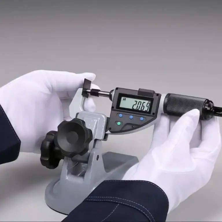
Verify Dimensions, Tolerances, Materials, and Assembly
Alpha prototypes are the first truly functional builds, often made via CNC or SLS to ensure structural performance.
Outputs
Works-like prototype
Engineering validation data (EVT-level)
Stage 4 – Testing, Optimization & Validation (Beta)
User Testing and Performance Validation
Beta testing simulates real usage. For a wearable device, all-day user testing revealed discomfort and button misplacement, prompting structural redesign.
Integrate Looks-like & Works-like
Beta units resemble production models and are used for user trials, market feedback, and certification testing.
Outputs
Integrated prototype
Test reports
Design improvement plan
Stage 5 – Pre-production & Manufacturing Preparation
Transition from Sample to Manufacturing
During this phase, I will promote small-batch trial production (PVT) to verify mold capabilities, process stability, and assembly efficiency. For example, for an injection-molded housing, we typically perform T0/T1 mold tests to check for shrinkage, deformation, and surface defects.
DFM/DFA Optimization
The goal of this phase is to reduce costs and improve yield:
Fewer parts
Easier assembly
Relaxed non-critical tolerances
Cost-efficient material/process adjustments
Outputs
Pre-production units (PVT)
Manufacturing plan & BOM
Cost analysis
What Technologies and Tools Are Needed for Prototype Manufacturing
Modern prototype manufacturing has moved beyond traditional hand-built samples into a fast, precise, digital engineering workflow. Each prototype stage requires different processes to verify appearance, structure, tolerances, and functional feasibility. Understanding these technologies helps you choose the most cost-efficient and effective prototype solution, improving overall product success.
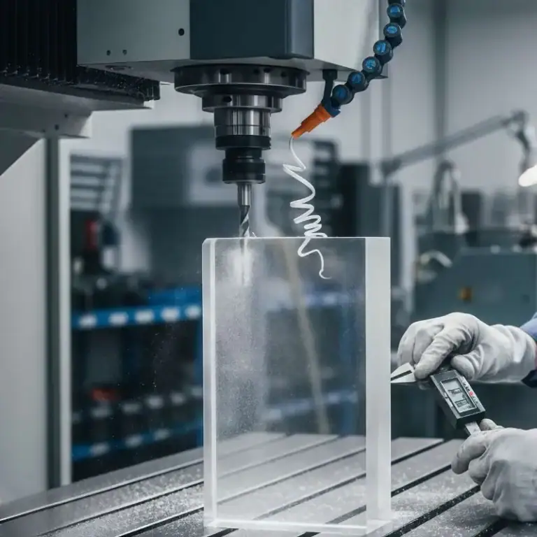
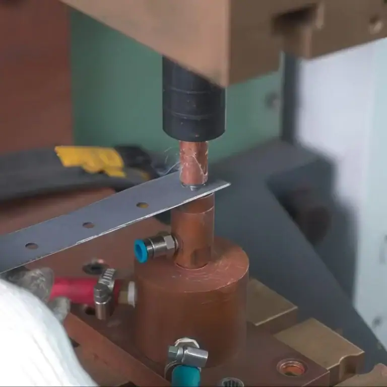
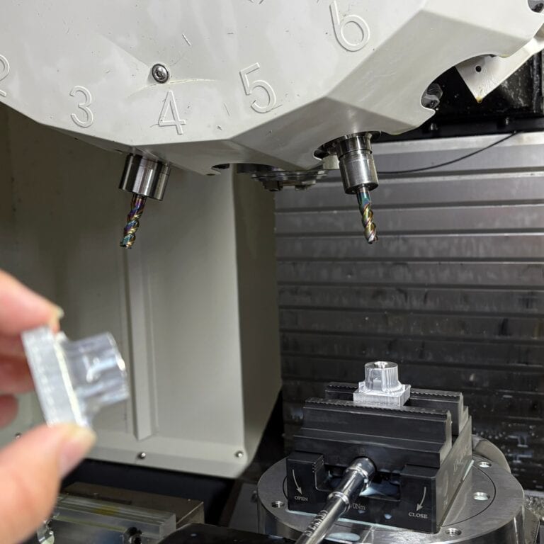
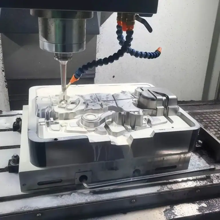
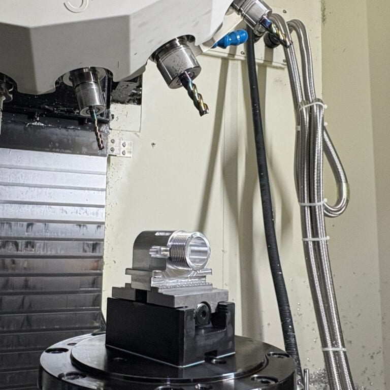
CNC Machining
CNC machining is one of the most common methods I use during the Alpha and Beta prototype stages. It is ideal for validating structural strength, assembly accuracy, and real material behavior.
Key Features
High precision: up to ±0.01 mm
Supports metals (aluminum, steel, titanium) and engineering plastics (POM, PA, PEEK)
Mimics mass-production material performance
Application Case
In a drone gimbal project, SLS-printed components failed under high-frequency vibration. Switching to CNC aluminum parts increased structural rigidity by nearly 3×, enabling the design to pass Beta testing. This proves CNC machining is irreplaceable for functional validation.
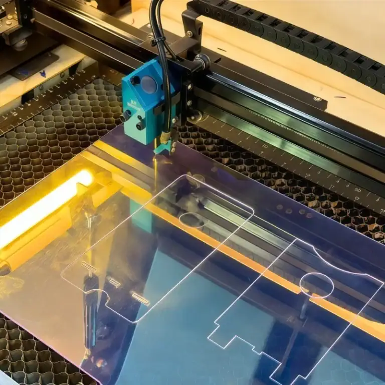
3D Printing (SLA / SLS / FDM)
SLA – High Appearance Accuracy
Ultra-smooth surfaces, ideal for aesthetic prototypes
Common for client demos and investor presentations
SLS / MJF – High Structural Strength
No support structures required
Capable of printing complex geometries
Perfect for early functional validation and jig/fixture development
FDM – Best Low-Cost Rapid Validation
Ideal for POC stage
Fastest and lowest-cost option
Real Case
In a home appliance project, I used SLS to print a continuous-wall airflow duct within 24 hours. CNC machining the same structure would have taken 5–7 days and cost significantly more.
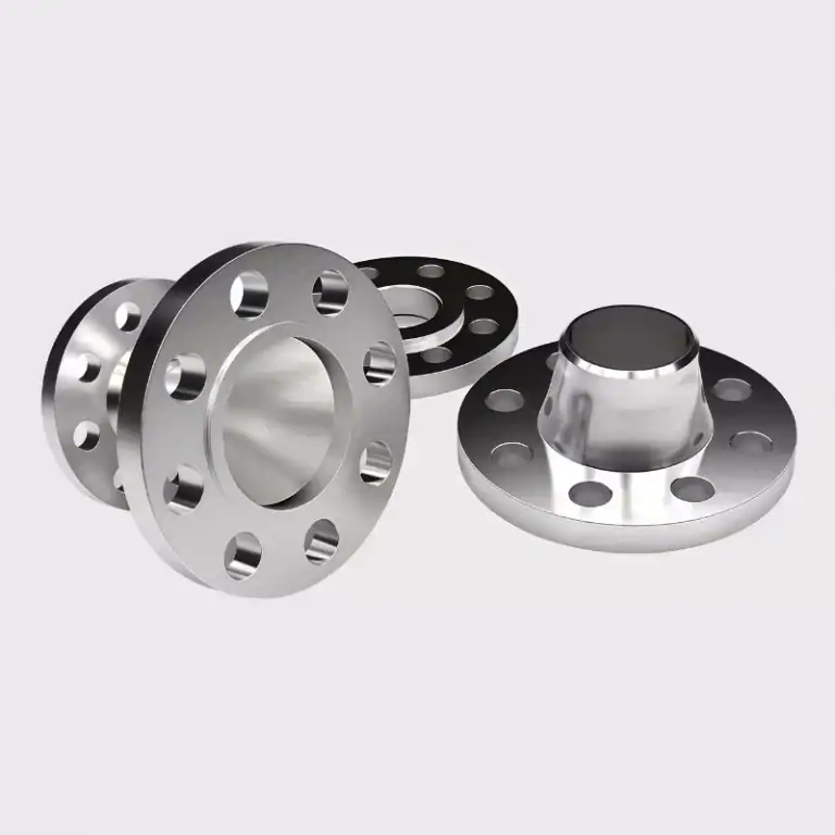
Urethane Casting (Vacuum Casting)
A widely used low-volume method in Beta stage, producing parts with appearance and strength close to injection molding.
Key Advantages
Low cost for small batches (10–50 pcs)
Suitable for market validation & assembly testing
Surface finish similar to mass-production injection parts
Best Use Cases
Wearable housings
Consumer electronics outer shells
Pre-production market testing
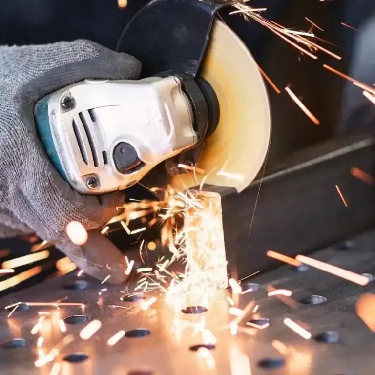
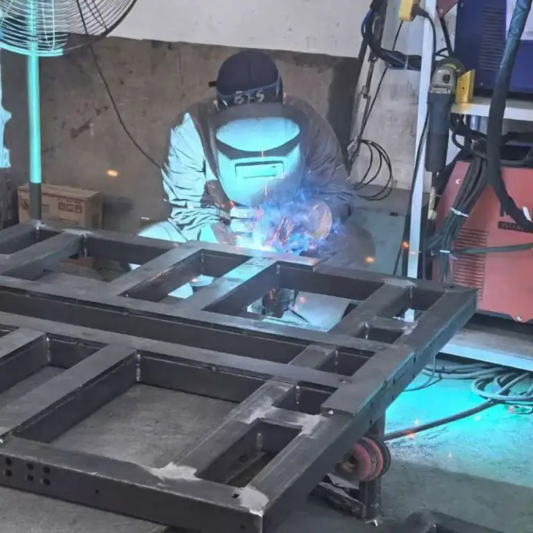
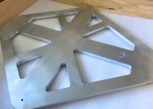
Sheet Metal Fabrication
Ideal for brackets, frames, housings, and industrial equipment prototypes.
Advantages
Fast fabrication: 1–3 days
High strength, design modifications are easy
More cost-effective than CNC for large components
Use Case
For a robot base prototype, we used sheet metal to validate hole positions quickly, avoiding CNC’s higher cost and longer delivery time.
CAD Modeling (SolidWorks / Fusion 360)
CAD is the foundation of all engineering prototypes, covering structural design, assembly validation, and mechanical motion analysis.
Structural Modeling
Parametric modeling reduces 60–80% of repetitive work
Accuracy up to ±0.01 mm, ideal for CNC/Injection/Sheet Metal
Material database (density, yield strength, modulus) improves simulation accuracy by 15–25%
Feature Tree allows full traceability of design changes
Assembly & Interference Check
Interference detection precision: 0.001 mm
Clearance analysis ensures battery/PCB/motor spacing: ≥0.2–0.5 mm
Exploded views help define assembly sequence and improve DFA
Motion Simulation
SolidWorks Motion / Fusion 360 Motion simulate real-world loads and mechanism behavior.
Key Simulation Data
Motion resolution: 10,000 steps/s
Torque/resistance curve error: <5%
Supports friction and damping models
Life-cycle prediction error: ±10%
Simulation Analysis (FEA / CFD)
Before Alpha builds, simulation can replace many physical tests, making the structure more mature.
Stress Analysis – FEA
Validates stiffness, strength, fatigue life
Stress concentration prediction error: <10%
Can simulate tension, bending, impact, and drop tests
Fatigue analysis estimates life cycles
Thermal Analysis
Predicts overheating risk and improves heat dissipation
Temperature prediction error <5°C
Simulates heat sinks, airflow, thermal sources
Helps optimize vent holes and airflow channels
CFD – Fluid Simulation
Used for airflow, water flow, ducts, pump structures
Flow-rate error: <10%
Optimizes curvature, inlet angles, and flow paths
Predicts pressure loss and vortex zones
Digital Twin (Virtual Prototype)
A Digital Twin is a full digital replica of a physical product. It can replace many Alpha/Beta tests.
Quantified Benefits
Reduces 20–40% of physical prototypes
Increases iteration speed 3×–5×
Cuts early development cost 25–35%
Raises first-time design success rate to >85%
Use Cases
Simulating mechanical performance in real environments
Predicting fatigue, heat, material aging
Pre-validating manufacturing processes (e.g., injection molding warpage prediction)
Real Case
In an injection-molded housing project, a Digital Twin simulation predicted 1.1 mm warpage. By adding reinforcement ribs, we reduced warpage to 0.3 mm, avoiding mold rework and saving over $8,000.
Key Strategies For Efficient Prototype Development
Efficient prototype development is not just about speed—it’s about validating the right functions, testing early, collaborating across teams, and optimizing both cost and timeline. Mastering these strategies can significantly improve first-pass success rates and accelerate the path from concept to production.
Focus On Critical Functions First
90% of prototype failures originate from insufficient testing of core functions. I typically categorize functions based on risk and priority:
Engineering Insights & Data
Early validation reduces rework cost by 30–50%.
In one wearable project, the team focused on appearance first and overlooked button durability—resulting in failure during Beta.
After restructuring the workflow, validating the switch mechanism first tripled the project’s first-pass success rate.
Test Early, Iterate Fast
“Fail early, succeed sooner” is the foundation of modern prototype stages.
Rapid technologies like SLS, FDM, and silicone casting allow meaningful testing long before Alpha.
Practical Tips
Validate mechanisms in the POC stage with 3D prints
Run Digital Twin simulations before Alpha to predict warpage, stress, or heat issues
Keep iteration cycles to 2–5 days, not weeks
Case Example
For a smart lock project, daily FDM iterations allowed us to cut the iteration timeline from 6 weeks to 2 weeks.
Cross-Team Collaboration
Efficient prototyping requires designers, engineers, and manufacturing partners to work as a unified team.
Industry Data
Poor cross-team communication accounts for 42% of product delays.
Effective workflows include:
Daily 15-minute sync between design, mechanical, manufacturing
CAD cloud collaboration for real-time updates
Supplier participation in early-stage DFM reviews
Cost & Time Optimization Strategies
The goal isn’t to build a perfect prototype—it’s to validate the right things with the right fidelity.
Key Optimization Principles
Choose the right process for each stage
Use alternative materials to validate form/fit/function
Replace 20–40% of physical tests with simulation
Common Pitfalls Across Prototype Stages
Teams often face issues like overly complex designs, poor manufacturability, limited testing, and communication gaps across prototype stages. These problems lead to rework, higher costs, and longer timelines. Identifying these pitfalls early can greatly improve prototype first-pass success.
Overly Complex Prototype Design
Many teams attempt to build “near-production” prototypes as early as the Alpha stage, resulting in overly complex structures while failing to validate core functions effectively.
Common Signs
Building a full structural model during the POC stage, slowing iteration
Too many mechanical parts, making it difficult to validate key functions
Using CNC machining or metal components too early, causing costs to rise quickly
Engineering Insights & Data
According to development statistics, 30–45% of rework is caused by over-engineering.
Prototypes should be validated by functional modules, not full structures all at once.
Real Case
A client created a CNC model with more than 20 parts in the very first iteration—yet the only requirement was to test the “button rebound force.”
This approach wasted over 80% of the budget and slowed development.
After switching to an SLA assembly module, the team completed the key validation in just 2 days.
Ignoring Manufacturability (DFM Issues)
Skipping DFM (Design for Manufacturing) considerations during early prototype stages often leads to large-scale rework during Beta or PVT builds.
Typical Problems
Undercut structures that cannot be injection-molded
Uneven wall thickness causing warpage
Excessive sharp corners increasing machining difficulty
Screw bosses too thin and prone to breaking
Supporting Data
Mold modifications typically cost 10–50× more than prototype-stage revisions.
33% of product delays are caused by DFM defects discovered in mass-production stages.
Engineering Case
In a small home appliance housing project, Digital Twin simulation predicted 1.1 mm warpage in the injection-molded part.
The design team initially overlooked rib structure optimization.
After adjustments, deformation dropped to 0.3 mm, successfully avoiding mold rework and saving over $8,000.
Insufficient Testing Or User Feedback
Many teams, driven by tight schedules, skip essential mid-stage testing or rely solely on internal evaluations, resulting in major issues during the Beta stage.
Common Issues
Alpha prototypes not tested enough for lifecycle, drop, or vibration
Lack of real user environment feedback (e.g., grip habits, torque requirements)
Insufficient sample size, preventing statistically valid evaluation
Industry Data
70% of user experience problems cannot be detected through lab testing alone
Increasing user feedback can improve product success rates by 40–60%
Poor Communication Between Design and Manufacturing
If design, engineering, and manufacturing teams fail to communicate effectively, prototype-stage errors quickly multiply.
Common Symptoms
No clear assembly sequence provided, causing incorrect builds
Manufacturing teams misunderstand tolerance requirements, leading to fitment issues
Suppliers not included in early DFM reviews
Engineering change orders (ECOs) not shared in time
Industry Data
42% of development delays are caused by communication gaps
Cross-department collaboration can shorten prototype cycles by 25–35%
FAQs
Do Prototypes Need To Be Perfect?
No, prototypes do not need to be perfect—especially in early stages. My goal is to validate assumptions, not achieve full refinement. In fact, research shows that teams reduce development time by up to 35% when they focus on “learning speed” instead of perfection. A prototype only needs to be accurate enough to test one function or hypothesis. Perfection matters later during Beta and Pre-Production stages, not during POC or Alpha.
Do All Stages Require Physical Prototypes?
Not every stage requires a physical prototype. Early in the process, I often rely on CAD models, FEA/CFD simulations, and Digital Twin tools, which can replace up to 40% of physical builds. Physical prototypes become essential at Alpha, Beta, and PVT stages, where functional, usability, and manufacturing validations are required. By combining virtual and physical iterations, I reduce cost by 25–40% and accelerate decision-making.
How Many Iterations Does A Prototype Need To Go Through Before It Becomes A Product?
In my experience, a product typically goes through 5–12 prototype iterations depending on complexity, risk level, and regulatory requirements. Hardware startups may run 3–5 loops at POC and Alpha, while consumer electronics often require 7–10 iterations before entering pilot production. Each cycle aims to reduce uncertainty—structural failures, tolerance issues, and user experience gaps. More iterations upfront usually reduce mass-production defects by 30–60%.
During The Initial Prototyping Phase What Manufacturing Processes Should You Use?
During the initial prototyping phase, I prioritize fast and low-cost processes such as FDM, SLA, SLS, and soft foam models. These allow me to validate shapes, mechanisms, and basic functions within 24–72 hours, at costs typically 70–90% lower than CNC machining. When mechanical strength matters, I may introduce MJF nylon or simple sheet-metal brackets. Speed and iteration volume matter far more than precision in this phase.
How To Manufacture A Rapid Prototype?
To manufacture a rapid prototype, I begin with a validated CAD model and choose a process that balances speed, cost, and required fidelity. For most projects, SLA/SLS/MJF delivers functional parts in 1–3 days. For high-strength components, I use CNC machining with simplified geometry. I also leverage digital simulations to reduce redesign loops by 25–35%. The key is iterative refinement—fast builds, fast tests, and fast decisions.
Conclusion
Prototype development is a structured journey—from uncertain concepts to verified, manufacturable products. Each stage reduces risk, refines design decisions, and ensures you’re building something users will love and manufacturers can produce efficiently. With the right method and tools, you can move from idea to production with confidence, speed, and professional rigor.If you have any further questions about the prototyping stage, or any other needs regarding prototyping, welcome to message us in any time!