In GD&T, profile of a surface defines a three-dimensional tolerance zone that controls how closely a manufactured surface follows its theoretical geometry. It is commonly used to manage complex curved or freeform surfaces that cannot be accurately controlled using traditional dimensional tolerances.
In this guide, you will learn what profile of a surface means, how it is defined in GD&T drawings, and how it is measured and applied in CNC machining to maintain accurate geometry and reliable part performance.
1.Limitations of Traditional Dimensional Tolerances
Traditional engineering drawings primarily rely on linear dimensions and size tolerances to define part geometry. However, when a component includes complex curves or sculpted surfaces, these methods become insufficient. In practice, relying only on dimensional tolerances often leads to accumulated deviations during manufacturing, which can result in assembly misalignment, reduced performance, and inconsistent product quality.
2.Need for Profile Control in Complex Surfaces
Complex surfaces require profile control because traditional tolerancing methods cannot accurately define curved or freeform geometries. These shapes demand a controlled three-dimensional tolerance zone to ensure they are manufactured as intended. Profile of a surface ensures the entire geometry remains within defined limits, helping maintain both functional performance and visual consistency.
3.Overview of GD&T Profile Controls
GD&T provides a range of profile tolerances for controlling complex geometries in both two-dimensional and three-dimensional applications. These controls define allowable variation across a surface, ensuring consistency and precision in manufacturing. In practical applications, selecting the right profile control depends on whether full-surface control or specific cross-sectional control is required, which helps optimize both quality and production efficiency.
4.Profile of a Surface vs Profile of a Line
Although both profile of a surface and profile of a line fall under the GD&T profile category, they control different aspects of a part’s geometry. Profile of a surface manages the entire three-dimensional surface, ensuring that the full feature geometry stays within the specified tolerance zone. On the other hand, profile of a line controls only the two-dimensional cross-sectional profile of the part, offering a more focused approach for certain applications, like cam profiles or specific edge contours.
| GD&T Control | What It Controls | Typical Use |
|---|---|---|
| Profile of a Surface | Entire 3D surface | Complex curved surfaces |
| Profile of a Line | Cross-section | Cam profiles, edge features |
| Flatness | Planar surfaces | Flat faces, reference surfaces |
| Position | Feature location | Holes, centers, and slots |
What Is a Profile of a Surface Tolerance Zone in GD&T?
Profile of a surface tolerance zone defines the allowable variation between the theoretical surface and the actual manufactured surface. In GD&T, this tolerance zone forms a three-dimensional boundary surrounding the nominal geometry, ensuring that the entire surface remains within the specified limits and maintains both dimensional accuracy and functional performance.
1.Understanding the Surface Profile Tolerance Zone
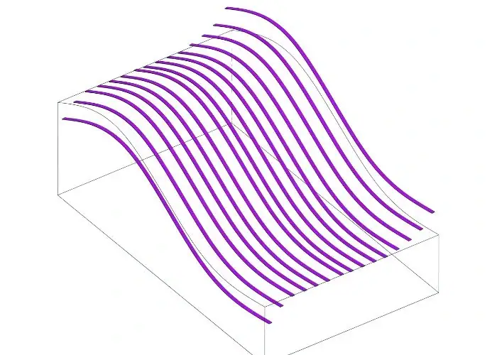
The profile of a surface tolerance zone represents a three-dimensional region that surrounds the theoretical surface geometry. In GD&T, this zone defines the allowable variation between the ideal design surface and the actual manufactured surface.
By limiting how far the surface can deviate from the nominal geometry, engineers can ensure that complex parts maintain both dimensional accuracy and functional performance during manufacturing and assembly.
2.Theoretical Surface
The theoretical surface is the ideal geometric shape defined by the CAD model or engineering drawing. It represents the exact surface that designers intend the final part to follow. During inspection, measurement data from the manufactured component is compared with this nominal surface to determine whether the part remains within the specified tolerance zone.
In modern manufacturing, the theoretical surface is typically derived directly from the 3D CAD model. This allows inspection systems such as CMM or optical scanners to evaluate thousands of points across the surface and verify whether the actual geometry stays within the defined profile tolerance limits.
3. Uniform Tolerance Zone
A uniform tolerance zone is the three-dimensional boundary that surrounds the theoretical surface at a consistent distance defined by the tolerance value. This zone determines how much the manufactured surface is allowed to deviate from the nominal geometry.
For example, if a surface profile tolerance of 0.2 mm is specified, the total thickness of the tolerance zone is 0.2 mm. The actual surface must remain entirely within this zone to meet the design requirement.
4.Bilateral Tolerance
In bilateral tolerance, the tolerance zone extends equally on both sides of the theoretical surface. This means the actual surface can deviate both inward and outward relative to the nominal geometry within the specified tolerance limits.
This type of tolerance is the most commonly used in engineering drawings because it provides balanced variation around the theoretical surface. It is particularly suitable for parts where symmetric geometric accuracy is required, such as turbine blades, aerodynamic panels, or precision housings.
5.Unilateral Tolerance
In unilateral tolerance, the allowable deviation occurs only in one direction from the theoretical surface. Instead of being centered on the nominal geometry, the tolerance zone lies entirely on one side of the surface.
This approach is useful when functional constraints require the surface to move in only one direction. For example, in mold design or sealing surfaces, engineers may allow outward variation but restrict inward deviation to avoid interference or maintain critical clearances during assembly.
Profile of a Surface Symbol
Understanding the profile of a surface symbol is essential for interpreting GD&T drawings correctly. This symbol indicates that a surface must remain within a defined tolerance zone relative to the theoretical geometry, allowing engineers to clearly specify surface accuracy and geometric requirements on engineering drawings.
1.GD&T Symbol for Surface Profile
Each GD&T tolerance has a unique symbol that represents a specific geometric control. The profile of a surface symbol indicates that the entire surface must lie within a specified tolerance zone surrounding the theoretical surface. This control allows engineers to manage complex curved or freeform geometries that cannot be accurately defined using simple dimensional tolerances.
2.Appearance of the Symbol
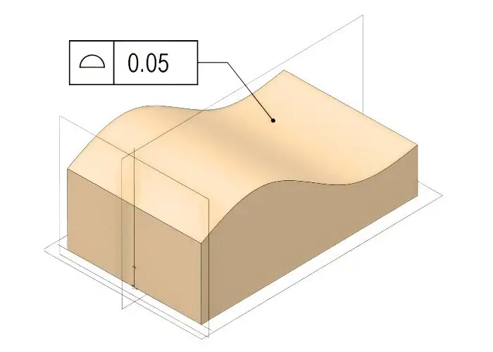
The profile of a surface symbol appears as a curved line resembling a surface contour. This visual representation indicates that the tolerance applies to the complete surface geometry rather than to a single dimension or cross-section. In engineering drawings, the symbol helps designers quickly identify that a surface profile tolerance is applied.
3.How the Symbol Appears on Drawings?
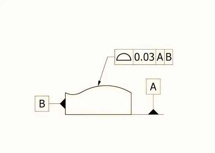
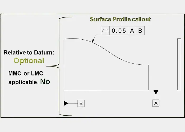
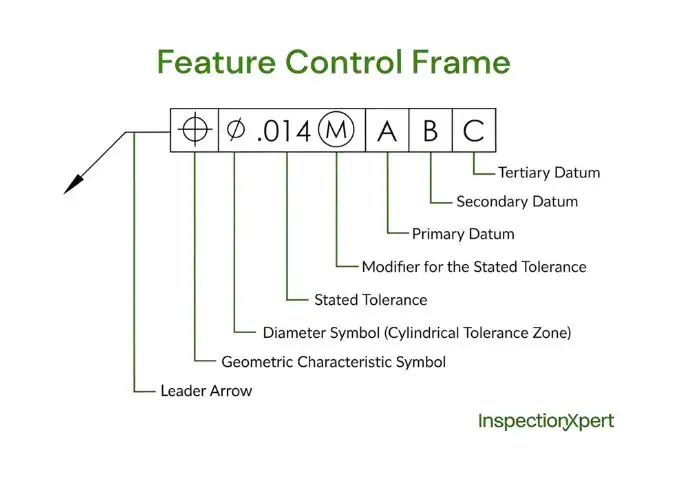
On engineering drawings, the surface profile symbol is placed in the first compartment of the feature control frame. It is typically followed by the tolerance value and optional datum references. These elements together define the allowable variation of the surface and how the surface should be evaluated during inspection.
4.Feature Control Frame for Surface Profile
Surface profile tolerances are specified using a feature control frame, which is the standard method used in GD&T to communicate geometric tolerance requirements. The feature control frame clearly defines the type of geometric control, the tolerance value, and any datum references required for inspection.
5.Geometric Characteristic Block
The first section of the feature control frame contains the geometric characteristic symbol. In the case of surface profile tolerance, this block includes the profile of a surface symbol, indicating that the tolerance applies to the entire surface geometry.
6.Tolerance Value Block
The second section of the feature control frame contains the tolerance value. This value defines the total allowable thickness of the tolerance zone surrounding the theoretical surface. For example, a tolerance of 0.2 mm means the entire surface must remain within a 0.2 mm tolerance band relative to the nominal geometry.
7.Datum Reference Block
If required, datum references appear in the following compartments of the feature control frame. These datums establish the reference coordinate system used to evaluate the surface during inspection. When datums are specified, the surface profile tolerance can control not only surface form but also its orientation and location relative to other features.
Composite Profile of a Surface
Composite profile of a surface tolerance is used in advanced GD&T to control both overall surface alignment and local surface form. By using two tolerance segments within one feature control frame, engineers manage global geometry relative to datums while refining local surface variations.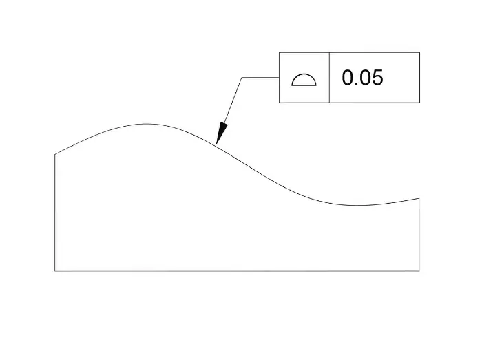
How Composite Surface Profile Works?
Composite surface profile uses a two-tier feature control frame to separate global control from local refinement. In my experience, this approach allows engineers to maintain overall alignment of the surface while still controlling small local deviations that could affect performance.
The top tolerance segment controls the entire surface relative to the datum system. The lower segment refines the surface form by limiting how individual surface elements can deviate from the nominal geometry.
Global vs Local Surface Control
One of the main advantages of composite surface profile is the ability to manage both global and local geometry. The upper tolerance ensures that the surface maintains its proper relationship to the part’s datum references, controlling orientation and location.
The lower tolerance focuses on smaller surface variations that occur during manufacturing. This ensures that local surface irregularities remain within acceptable limits while maintaining overall alignment.
Typical Applications of Composite Surface Profile
Composite surface profile tolerances are commonly used in industries that require extremely precise surface control. In aerospace engineering, turbine blades and aerodynamic panels often rely on composite profiles to ensure smooth airflow and consistent geometry.
In precision CNC machining, composite profile tolerances are also applied to complex molds, optical surfaces, and high-performance mechanical components where both global alignment and local surface accuracy are critical.
Benefits of Using Composite Profile Tolerance
Using composite surface profile allows engineers to simplify tolerance structures while maintaining strict geometric control. Instead of applying multiple separate tolerances, I can manage several geometric conditions within a single composite profile specification.
This not only simplifies engineering drawings but also improves inspection efficiency, since the measurement system can evaluate both global and local deviations simultaneously.
Common Mistakes When Using Profile of a Surface
Incorrect use of profile of a surface in GD&T often occurs when engineers misunderstand the tolerance zone, misuse datum references, or apply the control where simpler tolerances would work. These mistakes can lead to manufacturing errors, inspection problems, and unnecessary design complexity.
1.Confusing Profile of a Surface with Profile of a Line
A common mistake in geometric dimensioning and tolerancing (GD&T) is confusing profile of a surface with profile of a line. While both are used to control surface geometry, they serve different purposes. Profile of a line is applied to control a two-dimensional cross-section of a feature, such as a specific edge or contour. In contrast, profile of a surface controls the entire three-dimensional geometry of the feature, taking into account the full curvature and shape. Using the wrong tolerance can lead to incomplete or inadequate control, leaving parts of the surface outside the intended specifications. This can result in functional issues or poor assembly fitment.
2.Misunderstanding the Tolerance Zone
Another frequent mistake is misunderstanding the surface profile tolerance zone. The tolerance value defines the total thickness of the 3D tolerance zone surrounding the theoretical surface. It’s important to remember that this zone isn’t just a deviation in a single direction, but a uniform boundary in all directions. The entire manufactured surface must lie completely within this 3D boundary for the part to be considered within tolerance. Failing to account for this can lead to significant discrepancies in the final part, especially when dealing with complex or freeform geometries.
3.Incorrect Use of Datum References
Improper datum references can drastically affect how the profile of a surface tolerance controls the geometry of a part. When datum references are used, the tolerance controls not just the shape (form) of the surface, but also its orientation and location relative to other features. Incorrect or poorly chosen datum references can lead to inaccurate results during both manufacturing and inspection. This may cause parts to be misaligned during assembly or fail to meet functional requirements, resulting in costly rework or rejection.
4.Overusing Surface Profile Instead of Simpler Controls
While surface profile is a highly versatile and powerful tolerance, it should not be applied to every feature. In many cases, simpler tolerances such as flatness, position, or circularity can be used effectively to control specific geometric features. Overusing surface profile tolerance unnecessarily complicates the drawing, increasing both the complexity of the design and the cost of inspection. It’s important to use the right tolerance for the job to ensure efficiency and clarity in both design and quality control.
5.Ignoring Inspection Requirements
Surface profile tolerances often require advanced inspection tools, such as CMM (Coordinate Measuring Machines) or 3D scanning systems, to measure the geometry accurately. If inspection capabilities are not considered during the design stage, verifying the tolerance may become difficult, time-consuming, or costly. It’s essential to ensure that the required measurement tools are available and that the inspection process is feasible before finalizing the design. Failing to account for these requirements can lead to delays, increased costs, or challenges in ensuring that parts meet the specified tolerances.
How to Measure Profile of a Surface?
Measuring profile of a surface in GD&T involves comparing the manufactured surface with the theoretical CAD geometry to determine whether the entire surface remains within the specified tolerance zone. Engineers typically use precision inspection methods to evaluate surface deviations and verify geometric accuracy.
1.Surface Profile Inspection Methods
To verify profile of a surface tolerance, engineers typically use high-precision measurement technologies capable of capturing detailed surface geometry. These systems collect data points from the actual surface and compare them with the nominal CAD model.
The goal is to determine whether the measured surface remains completely within the defined three-dimensional tolerance zone when compared with the nominal CAD model.
2.Coordinate Measuring Machine
A Coordinate Measuring Machine (CMM) is one of the most widely used tools for surface profile inspection. In my inspection process, the CMM probe collects a large number of points across the surface and records their spatial coordinates. These points are then compared with the CAD reference model to calculate deviations and determine whether the profile tolerance requirement is satisfied.
3.Optical Scanning
Optical scanning technologies such as laser scanners or structured-light scanners are commonly used for complex freeform surfaces. These systems capture millions of measurement points in a short time, creating a detailed 3D digital representation of the surface. The scanned model can then be analyzed to evaluate how closely the manufactured surface matches the theoretical geometry.
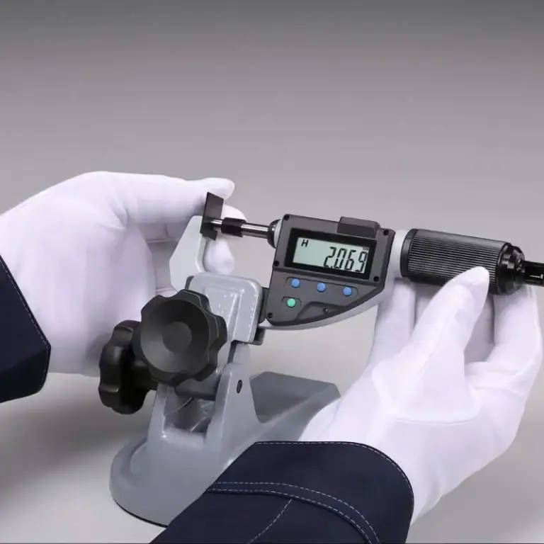
4.Surface Profilometers
Surface profilometers are typically used to measure smaller areas or detailed surface features. These instruments trace the surface along a specific path and record variations relative to a reference profile. Although profilometers do not measure the entire surface, they are very useful for evaluating critical sections or local surface accuracy.
5.Typical Inspection Workflow
The inspection process for profile of a surface generally follows a structured workflow that combines CAD data with measurement results. In my experience, following a clear inspection procedure helps engineers identify deviations quickly and ensures consistent quality evaluation during manufacturing.
6.Creating the CAD Reference Surface
The first step in inspection is defining the theoretical reference surface using the CAD model. This model represents the ideal geometry that the manufactured part should match. Inspection software imports this CAD surface and uses it as the baseline for all measurement comparisons.
7.Comparing Measured Data with the Nominal Model
After collecting measurement points, inspection software compares the data with the nominal CAD surface. The software calculates the deviation of each measured point and determines whether the entire surface lies within the specified tolerance zone. Color deviation maps are often generated to visualize areas that exceed the allowed tolerance.
Key Design Guidelines for Profile of a Surface
Understanding profile of a surface in GD&T helps engineers control complex geometries and ensure manufactured parts match the intended design. In practice, surface profile is one of the most powerful geometric tolerances because it can simultaneously control multiple aspects of surface geometry.
Important Engineering Notes
When applying profile of a surface tolerance, engineers must understand how the tolerance zone functions and how datum references influence the geometric control of a part.
Proper use of surface profile tolerance is essential to preserve design intent, ensuring that parts meet both functional and aesthetic requirements. This tolerance prevents unnecessary complexity in both manufacturing and inspection, avoiding costly rework or delays. The right balance of control and flexibility is key to achieving high-quality parts with minimal effort in production.
Surface Profile Controls Complex Geometry
Profile of a surface is an advanced tolerance specifically designed to control complex, curved, or freeform surfaces that cannot be adequately defined using basic dimensional tolerances. These include components with intricate geometries such as aircraft panels, turbine blades, and automotive body parts.
The tolerance defines a three-dimensional zone that surrounds the theoretical surface, within which the actual surface must remain. This ensures that the shape, form, and contour of the surface stay consistent and within acceptable limits throughout the manufacturing process. It also ensures that the part functions as intended in its application.
The use of profile of a surface allows engineers to specify highly detailed and complex shapes, ensuring that parts fit into assemblies or perform in their respective roles without causing issues related to fit or function. In industries such as aerospace and automotive manufacturing, where surface accuracy is critical, profile of a surface tolerance ensures that even the most intricate parts meet the required performance standards.
Can Control Form, Orientation, and Location
A key benefit of profile of a surface tolerance is its ability to manage multiple geometric characteristics simultaneously. When datum references are included, the surface profile tolerance can control the form, orientation, and location of a surface in relation to other features of the part. This allows for comprehensive control of part geometry, ensuring that not only is the surface the correct shape, but also that it is oriented and positioned correctly relative to other features.
-
Form control ensures the surface maintains the correct shape, preventing warping or distortion.
-
Orientation control ensures the surface is aligned correctly, which is essential for parts that must interface with other components in mechanical assemblies.
-
Location control ensures that the surface is in the correct spatial position, which is crucial when parts must fit together within strict tolerances.
This comprehensive control helps reduce the risk of misalignment, poor fit, or incorrect assembly, improving overall product reliability.
Can Be Used With or Without Datum
One of the advantages of surface profile tolerance is its flexibility. Surface profile tolerances can be specified with or without datum references, depending on the design and manufacturing needs.
-
Without datum references, the surface profile tolerance controls only the form of the surface, ensuring that the surface maintains the desired shape without reference to any other features. This is typically used for simple, standalone parts or when the precise orientation and location of the surface are not critical.
-
With datum references, the tolerance controls not only the form but also the position and orientation of the surface relative to other critical features of the part. This is particularly useful in situations where multiple components must fit together precisely, such as in automotive assembly or aerospace systems, where precise alignment is required for the part to function properly.
This flexibility allows engineers to tailor the surface profile tolerance to the specific needs of each part and its function, making it a versatile tool in geometric control.
Widely Used for Complex Engineering Surfaces
Surface profile tolerances are commonly used in industries where high geometric accuracy is essential. These industries often require complex, freeform shapes that cannot be defined using basic dimensional tolerances. Aerospace, automotive, medical devices, and precision molding are just a few examples of industries that rely on surface profile control for:
-
Ensuring aerodynamic performance in aircraft components.
-
Maintaining aesthetic quality in automotive body panels.
-
Achieving functional accuracy in medical implants or devices.
-
Ensuring high-precision mold cavity shapes in manufacturing processes like injection molding.
In all these applications, maintaining consistent surface geometry is essential to the performance, safety, and durability of the final product. Surface profile tolerances ensure that the surfaces meet strict design criteria, improving the overall quality of the manufactured part.
Requires Advanced Inspection Methods
Due to the complexity of controlling an entire 3D surface, surface profile tolerance requires advanced inspection methods to verify the part’s geometry. Traditional inspection techniques are often insufficient for measuring complex freeform surfaces, so specialized tools are needed to ensure that the surface lies within the specified tolerance zone.
Common advanced inspection tools include:
-
Coordinate Measuring Machines (CMM): These machines use probes to collect precise data points across the surface, which are then compared to the nominal CAD model to assess deviations.
-
Optical Scanning: Laser scanners or structured-light scanners can capture millions of data points rapidly, creating a 3D model of the surface that is analyzed for accuracy.
-
Surface Profilometers: These tools are used for measuring smaller areas of a part’s surface, focusing on local variations or critical features.
Without these advanced inspection tools, it would be difficult, time-consuming, or costly to verify whether the manufactured surface meets the strict surface profile tolerance. Advanced software that integrates these tools also plays a crucial role in the inspection process by providing deviation maps and tolerance analysis to visualize areas that exceed the allowable tolerance zone.
Applications of Surface Profile Tolerance
Surface profile tolerance is widely used in industries where complex curved or freeform surfaces must be controlled accurately. It helps engineers maintain precise surface geometry, ensure proper assembly alignment, and achieve consistent functional performance in advanced manufacturing applications
1. Aerospace Components
Aerospace components often include complex aerodynamic surfaces, such as aircraft panels, turbine blades, and airfoil structures. These parts require strict geometric control to ensure they perform under extreme conditions. Profile of a surface tolerance is crucial in maintaining accurate airflow geometry and aerodynamic properties, which directly impact the aircraft’s performance, fuel efficiency, and safety. By ensuring the proper surface geometry, manufacturers can achieve the desired aerodynamic behavior, reducing drag and optimizing fuel efficiency.
2. Automotive Parts
Automotive components, including body panels, engine housings, and structural parts, frequently require surface profile control to meet both functional and aesthetic requirements. For body panels, such as doors, hoods, and roofs, the surface profile tolerance ensures a smooth and even finish, which is vital for both the vehicle’s appearance and aerodynamic performance. In engine housings and other mechanical parts, surface profile tolerance ensures that surfaces fit together precisely, minimizing gaps and ensuring structural integrity during vehicle assembly.
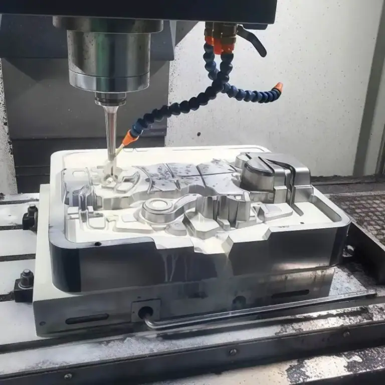
3. Precision Molds
Injection molds and die-casting molds play a crucial role in ensuring the quality of molded products, as they directly define the final shape of the part. For these molds to produce high-quality, consistent products, the surface geometry must be precise. Profile of a surface tolerance ensures that the mold cavities are accurately shaped, which helps maintain product quality across multiple production runs. By maintaining consistency in mold geometry, surface profile tolerance improves mold longevity, reduces the likelihood of defects, and enhances overall production efficiency.
4. Consumer Electronics Housings
Many consumer electronics, such as smartphones, tablets, and wearables, feature complex, curved housings designed for both aesthetics and functionality. Surface profile tolerance plays a key role in ensuring that these housings have the right curvature, smoothness, and fit for internal components like screens, batteries, and buttons. In addition to improving the overall look and feel of the device, accurate surface geometry ensures that internal components fit correctly, enhancing the device’s durability and performance. Surface profile control also helps maintain consistent manufacturing processes, ensuring that each product meets high-quality standards.
FAQs
What does profile of a surface mean in GD&T?
Profile of a surface in GD&T is a geometric tolerance used to control the entire shape of a surface relative to its theoretical design geometry. It defines a three-dimensional tolerance zone surrounding the nominal surface, ensuring the manufactured part remains within limits to maintain fit, function, and reliable performance in complex assemblies.
What is the symbol for profile of a surface?
The profile of a surface symbol is represented by a curved line indicating the contour of a surface. It is used within a Feature Control Frame together with tolerance values and datum references, specifying that the entire surface must remain within a defined three-dimensional tolerance zone during manufacturing and inspection.
How is profile of a surface measured in practice?
Profile of a surface is measured using precision inspection equipment such as Coordinate Measuring Machines (CMM), optical scanners, or advanced 3D metrology systems. These tools capture multiple data points across the surface and compare them with the CAD model to evaluate deviations and verify compliance with tolerance requirements.
Can profile of a surface be used without a datum reference?
Yes, profile of a surface can be specified without datum references when only the form of the surface needs to be controlled. In this case, the tolerance limits shape variation but does not control position or orientation, making it suitable for cosmetic surfaces or features with less strict alignment requirements.
What is the difference between profile of a line and profile of a surface?
Profile of a line controls the shape of a two-dimensional cross-section, ensuring each section stays within a defined tolerance band. In contrast, profile of a surface controls the entire three-dimensional geometry, making it more suitable for complex parts where full surface accuracy is required across all areas.
When should profile of a surface be used in engineering design?
Profile of a surface should be used when parts include complex curves, freeform geometries, or aerodynamic shapes that cannot be defined using traditional dimensional tolerances. It ensures the entire surface meets design intent, especially in applications requiring precise fit, sealing performance, or structural consistency.
What is a profile tolerance zone in GD&T?
A profile tolerance zone is a three-dimensional boundary surrounding the theoretical surface that defines allowable variation. The manufactured surface must remain completely within this zone, controlling overall geometry rather than individual dimensions and ensuring consistent shape, function, and assembly performance.
What is the difference between unilateral and bilateral profile tolerance?
Bilateral tolerance allows variation on both sides of the theoretical surface, providing balanced deviation around the nominal geometry. Unilateral tolerance allows variation in only one direction, which is useful when functional requirements restrict movement on one side, such as sealing surfaces or interference conditions.
Conclusion
Understanding Profile of a Surface helps engineers control complex surfaces and maintain consistent part quality. This GD&T tolerance plays an important role in aerospace, automotive, and precision machining applications.
At TiRapid, our engineers specialize in manufacturing precision CNC parts with tight GD&T tolerances and complex geometries. Upload your CAD files today and our team will provide a fast and professional quote