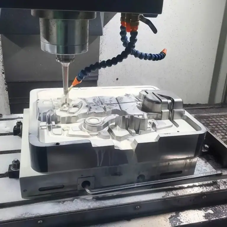
Stainless steel has become an important material in modern manufacturing due to its high strength, corrosion resistance, and good surface quality requirements. However, machining stainless steel is not easy: its low thermal conductivity easily leads to cutting heat accumulation, and its high strength increases the risk of tool wear. Especially in CNC milling, choosing reasonable milling stainless steel speeds and feeds (cutting speed Vc and feed rate Fz) is critical. This article starts with cutting parameter selection, tool configuration, and cooling strategy, summarizing my practical experience and optimization tips in stainless steel milling to help you improve processing efficiency and reduce costs.
Why Speed And Feed Are Particularly Important In Stainless Steel Processing
In my many years of CNC machining experience, stainless steel is definitely one of the materials that “tests parameter control skills the most”. Its notable characteristics are high hardness, strong toughness, and poor thermal conductivity . These characteristics directly determine that the speed and feed rate must be precisely optimized. Due to poor thermal conductivity, the heat generated during the machining process is difficult to conduct and tends to concentrate on the cutting edge of the tool, resulting in rapid tool temperature rise and increased wear . Data shows that if the cutting parameters are not appropriate, the tool life can be shortened by more than 30% , the surface quality can drop by 20% , and even chipping and burning of the tool may occur.
Another challenge is tool sticking and burrs . Under high temperature and friction conditions, stainless steel chips tend to stick to the tool, forming built-up edge, which sharply deteriorates the surface roughness of the cutting and increases cutting resistance. To deal with this situation, I will choose a lower cutting speed, appropriate feed rate and sufficient coolant to reduce the cutting temperature and stabilize the cutting process.
Different grades of stainless steel (such as 304, 316, 17-4PH ) have obvious differences in performance:
304 is relatively soft and easy to stick to the knife, suitable for sharp knives and large chip removal space .
316 has strong corrosion resistance but high cutting resistance, so it is necessary to optimize the tool coating and cooling method .
17-4PH is a precipitation hardening steel with high hardness and severe work hardening, requiring layered cutting and equipment with better rigidity.
For this reason, when machining stainless steel, the speed and feed are not “the faster the better”, but need to be set comprehensively according to material properties, tool type and cooling conditions , and real-time monitoring of tool wear and workpiece surface quality. By scientifically selecting parameters, it is possible to ensure machining efficiency , extend tool life and improve product consistency.
What Is Speed And Feed Rate
In CNC machining, “speed” and “feed rate” are the core parameters that determine the machining effect. Speed usually refers to the spindle speed , that is, the number of revolutions per minute (RPM) of the tool, which directly affects the frequency of contact between the cutting edge and the material. For example, high-speed cutting of more than 10,000 RPM is often used when machining aluminum, while stainless steel machining needs to be reduced to 3000-6000 RPM to avoid overheating and tool wear.

Feed rate is the distance the tool pushes the workpiece forward per unit time, usually measured by feed rate (mm/min). If speed is like “how fast the tool turns”, then feed rate is “how fast it cuts”. The combination of the two directly determines the cutting force, surface roughness and tool life.
In addition, there are several key concepts in cutting parameters:
Feed per Tooth (fz) : The distance each tooth advances during cutting, generally between 0.02–0.2 mm/tooth, depending on the tool diameter and material hardness.
Cutting Speed (Vc) : The linear speed of the tool cutting edge on the workpiece surface, usually expressed in meters per minute (m/min). Different materials have recommended ranges, for example, aluminum alloy is about 300-600 m/min, while stainless steel is only 60-180 m/min.
There is a calculation formula between these parameters, which is not complicated:
Spindle speed N = (1000 × cutting speed Vc) / (π × tool diameter D)
Feed rate F = feed per tooth fz × number of teeth Z × spindle speed N
After understanding these parameters, we can flexibly adjust them according to the material characteristics and tool conditions. For example, when processing carbide steel, we can appropriately reduce the feed rate and increase cooling, while processing plastics, we can increase the feed to avoid melting. Mastering these basic calculations can not only make the processing more stable, but also effectively extend the tool life and improve production efficiency.
How To Set The Appropriate Speed And Feed
Before the machine tool is officially turned on, the speed and feed rate settings almost determine the surface quality, dimensional accuracy and tool life of the finished product. My experience is that you should first look at the tool diameter , number of teeth and material hardness , which are the basis of all calculations. For example, the same 10 mm diameter tool has completely different parameters for machining aluminum and machining 304 stainless steel: aluminum allows a spindle speed of 10,000 RPM or even higher, while 304 stainless steel is best controlled between 3,000–5,000 RPM.
Use formulas and online calculators to help you choose
I usually start with two formulas:
Spindle speed N = (1000 × cutting speed Vc) ÷ (π × tool diameter D)
Feed rate F = feed per tooth fz × number of teeth Z × spindle speed N
These formulas are actually not complicated. Many online calculators can complete them automatically, such as the calculation tools provided by Machining Doctor or Kennametal, which can directly give recommended values based on material, tool diameter and number of teeth.
The Difference Between Roughing And Finishing
When roughing, I prioritize efficiency, using higher feeds and deeper cuts, such as 0.1 mm/tooth for 304 stainless steel . When finishing, the focus is on surface quality and dimensional stability. I usually reduce the feed per tooth to 0.03–0.05 mm/tooth and reduce the depth of cut to ensure that the surface roughness can be controlled within Ra 1.6 μm .
Take 304 stainless steel as an example: the recommended cutting speed is 60–120 SFM (about 18–36 m/min) , and the spindle speed of a 10 mm diameter four-flute end mill is calculated as follows:
N = (1000 × 30) ÷ (π × 10) ≈ 955 RPM
With a feed rate of 0.05 mm/tooth, the feed rate of the four-edge tool is:
F = 0.05 × 4 × 955 ≈ 191 mm/min
These numbers are not rigid, I will make appropriate adjustments based on the rigidity of the machine tool, the cooling conditions, and the type of tool coating. For example, when using a TiAlN coated tool, the speed can be slightly increased because it is more heat resistant.
Common Stainless Steel Milling Parameter Reference Table (Simple And Easy To Check)
Stainless steel is a very special material with high hardness, strong toughness and poor thermal conductivity . The heat generated during cutting is often not easy to dissipate. If the parameters are set improperly, the tool wear will accelerate at best, and the tool will directly break or even burn, wasting tool costs and working hours. Especially in common grades such as 304, 316, and 17-4PH, although they are all called “stainless steel”, the machinability varies greatly.
I have found an experience in actual production: instead of memorizing complex formulas, it is better to have a reference table of common parameters first, and then adjust them in combination with the actual machine tool, tool and cooling method .
For example, when I use TiAlN coated carbide tools to process 304, I usually choose a cutting speed of 200-250 SFM and a feed rate of 0.03-0.06 mm/tooth , which is enough to ensure the balance between tool life and processing efficiency. If it is 17-4PH, I will actively reduce it to 120-180 SFM , and give priority to coarse-tooth tools to reduce cutting heat.
These parameters are a basic starting point, not an absolute value. Each machine tool has different rigidity, different fixture stability, and different coolant systems, which will affect the actual available parameters . I usually recommend starting with the middle value in the table, and then find the “sweet spot” by slightly increasing or decreasing the speed and feed. Experienced engineers can even judge whether the current cutting state is reasonable based on the cutting sound and chip color.
“must-check parameter table before starting up” that I have accumulated over many years in the factory . It is simple and easy to use, especially suitable for novices or small batch proofing for quick reference to avoid detours.
Stainless Steel Milling Common Parameters Reference Table (Extended Version)
| Stainless steel types | Recommended speed (SFM) | Feed per tooth (mm) | Recommended tool type | Ø10mm Tool Spindle Speed (RPM)* |
| 304 Austenite | 200–250 | 0.03–0.06 | Carbide end mills (TiAlN coating) | 2,430–3,040 |
| 316 Austenite | 180–230 | 0.02–0.05 | Coated end mills (TiAlN, AlTiN) | 2,190–2,790 |
| 303 Free cutting | 250–300 | 0.04–0.08 | Carbide or high speed steel end mills | 3,040–3,650 |
| 410 Martensite | 180–220 | 0.03–0.06 | Coated carbide tools | 2,190–2,670 |
| 420 Martensite | 150–200 | 0.03–0.05 | Coated carbide tools | 1,820–2,430 |
| 17-4PH precipitation hardening | 120–180 | 0.03–0.06 | Coarse tooth carbide end mill | 1,460–2,190 |
| 2205 Duplex | 130–180 | 0.02–0.05 | High hardness coated carbide cutting tools | 1,580–2,190 |
* Calculation formula: RPM = (SFM × 3.82) ÷ tool diameter (mm) , Ø10mm in the table is an example.
Usage And Tips
Use the middle value first : When you try cutting for the first time, use the middle value of the recommended range (for example, for 304, you can use 225 SFM, 0.045 mm/tooth first).
Gradual fine-tuning : Determine whether the speed or feed needs to be adjusted based on the cutting sound and chip color.
Tool selection : Austenitic types (304, 316) have severe tool sticking, so it is recommended to use sharp tools + sufficient cooling . Precipitation hardening (17-4PH) requires coarse-tooth tools + low cutting depth .
Batch processing suggestions : A moderately low feed rate per tooth can extend tool life , and single-piece proofing can moderately increase speed and improve efficiency.
8 Key Factors Affecting Processing Speed And Feed
In the actual process of milling stainless steel, I found that speed (SFM) and feed (Feed per Tooth) are not fixed parameters , but a dynamic process that needs to be constantly adjusted. The setting of parameters often depends on the combined influence of material properties, tool status and on-site processing environment. Even for the same machine tool and the same batch of materials, the processing performance may be completely different as long as the environment or tool conditions are different. If these influencing factors are ignored, it is easy to cause problems such as tool chipping, workpiece burns, and severe surface burrs, which will eventually lead to increased costs and delays in construction.

Material Hardness And Type
The strength and toughness of stainless steel vary greatly. For example, the cutting resistance of 304 and 316 is significantly higher than that of 303 free-cutting steel, and precipitation hardened steels such as 17-4PH are more prone to tool chipping. Generally speaking, for every 10% increase in material hardness, the speed needs to be reduced by 10%~20%, otherwise the tool life will be significantly shortened.
Depth And Width Of Cut
As the depth of cut doubles, the cutting forces almost double, which means that if you increase the depth of cut from 1mm to 2mm, the spindle load and heat will increase significantly, and the speed must be reduced to prevent the tool from becoming unstable or the workpiece from deforming.
Tool Sharpness And Geometry
The cutting performance of a new tool and a worn tool is completely different. The bluntness of the tool will significantly increase the friction heat, resulting in an increase in the temperature of the cutting area. I usually replace or re-grind the tool when the wear exceeds 0.2mm, and reduce the cutting resistance by optimizing the front and back angles of the tool.
Tool Materials And Coatings
High-performance coated tools such as TiAlN and AlTiN perform well in stainless steel machining and can withstand higher temperatures and feed rates , while uncoated high-speed steel tools need to reduce their speed by 20% to 40%. Different tool coatings often determine whether the parameters can “run faster”.
Cooling And lubrication Conditions
Stainless steel has poor thermal conductivity and heat easily accumulates in the cutting area. I almost always choose high-pressure emulsion or oil mist cooling when machining, especially when milling deep cavities or high-speed milling. The cooling effect directly determines whether the tool life can be extended by more than double.
Machine Tool Rigidity And Fixture Stability
Insufficiently rigid machine tools or fixtures will generate vibrations during high-speed machining, resulting in tool chipping or poor surface roughness. I usually decide whether to use layered cutting or reduce the feed per tooth based on the rigidity of the machine tool in exchange for machining stability.
Program Path And Feed Method
An unreasonable path will cause a surge in instantaneous cutting load. For example, right-angle feed and full-width cutting are prone to impact and heat generation. I am used to using arc feed or dynamic milling strategies, and try to control the cutting width to 30%~50% of the tool diameter to ensure a smooth cutting process.
Operational Experience And Real-Time Adjustment
This is the key to implementation. Experienced technicians will fine-tune parameters at any time based on chip color, cutting sound, and machine tool load. For example, blue chips indicate high temperature, and you need to reduce the cutting speed or increase cooling . If the tool whistles, you may need to reduce the feed or optimize the tool extension.
In summary, speed and feed parameters are not values that can be set once and then ignored , but a process that requires dynamic balance. Every time you change the tool, material or process, you need to re-examine these parameters. Even if you only fine-tune them by 10% to 15%, it may increase the tool life by more than 30% and significantly improve processing stability and finished product qualification rate.
Several Tips To Improve The Quality Of Stainless Steel Processing
In daily stainless steel processing, I find that many seemingly insignificant details often directly determine the difference in the quality of the finished product. Especially when facing materials with strong toughness and poor thermal conductivity such as 304, 316 and even 17-4PH, reasonable processing techniques can not only reduce tool wear, but also significantly improve surface quality and dimensional accuracy.
The following tips are the “simple and effective” methods I have summarized after long-term practice :
First, down milling is preferred. In down milling, the cutting direction of the tool is the same as the workpiece feed direction, the cutting thickness is from large to small, and the cutting force direction is relatively stable, which can reduce the problem of workpiece pulling and tool vibration, especially when processing thin-walled parts. I switch to down milling at a high cutting speed (SFM), which often allows the surface roughness to drop directly from Ra 1.6 μm to about Ra 0.8 μm.
Second, it is more reliable to cut in multiple times than to cut all the way through with one knife. Stainless steel has high hardness and poor thermal conductivity, so cutting heat is not easy to conduct. Deep cutting can easily cause tool overheating or even chipping. I usually adopt the strategy of “layered cutting”: for example, when the total cutting depth is 6mm, cut it in 3 times, 2mm each time, instead of cutting all the way through with one knife. This will extend the tool life by at least 20%, and significantly reduce processing vibration.
Third, use the color of the chips as a temperature “alarm”. The chips are the most direct temperature feedback signal: yellowish metallic luster means the temperature is normal, bluish means overheating, and even a burning smell means you have to stop the machine immediately for inspection. I often adjust the feed rate or coolant flow rate in time according to the chip color during the trial cutting stage to ensure that the temperature rise is controlled within a reasonable range.
Fourth, do a test cut before processing. The risk of stainless steel processing is that it is highly unpredictable, and even hardness varies from batch to batch. Every time I come into contact with a new material or a new tool, I will first test cut 12mm in a non-critical position to quickly confirm whether the vibration, cutting load, surface effect and cooling status are normal. Although it only takes 23 minutes longer, it can avoid 90% of the risk of scrapping.
In summary, these techniques are not complicated, but can bring about qualitative improvement in actual operation. By reducing vibration through down milling, reducing thermal stress through multiple cutting, judging temperature by chip color, and ensuring safety through trial cutting, machining stability is significantly improved, tool life is extended, and surface roughness can be stabilized at Ra 1.6 μm or even better.
Common Mistakes Beginners Make
Machining stainless steel is far more complicated than you might think . It has high hardness, strong toughness, and poor thermal conductivity. Once the parameters or operation methods are slightly deviated, serious tool wear, chipping, and even workpiece scrapping will occur. These mistakes are often not due to lack of experience, but because many details are easily overlooked, such as tool selection, coolant dosage, cutting method, clamping stability, etc. Especially for novices, they habitually rely on “experience parameters used by others” without considering the differences in their own equipment and tools, and the final processing quality is terrible.
I have summarized the most common types of “novice pitfalls” in the workshop, which are basically lessons I have personally experienced:
The First Category: Parameters Are Copied Directly From Others, But The Materials And Tools Are Completely Different.
Many novices think that they can just search for a set of parameters online and copy them. What is the result? Others use high-end carbide tools with coatings, and you use ordinary tools. As a result, the cuts are full of burrs and accompanied by tool chipping. The correct approach is: first confirm the tool material, coating and hardness of the material being processed, and then adjust the speed and feed appropriately.
The Second Type: Cutting All The Way Through Without Considering The Tool Life
. In order to save time, many people cut very deep and cut all the way through. However, this will increase the cutting heat, the tool will wear quickly, and the surface quality will also deteriorate. Experience tells me that multiple layer cutting is faster and safer, and the tool life can be extended by more than 30%.
The Third Category: Insufficient Coolant, The Tool Is Blued Without Knowing it
Especially when processing 304 or 316 stainless steel with poor thermal conductivity, if the cooling is not in place, the tool temperature will easily soar to over 600℃, and once the blue “tempering color” appears, the tool is basically scrapped. My suggestion is: emulsion or oil mist cooling must be sufficient and aimed at the cutting point.
Category 4: The Workpiece Is Not Clamped Firmly, And The Precision Is lost
. The loose fixture or unreasonable clamping method will turn the entire part into “scrap copper and rotten iron” after processing. Once, because the vise was not locked tightly, the entire workpiece flew out of the machine tool, but fortunately no one was injured. Therefore, always remember to check the clamping status before starting the machine tool.
FAQs
What Speed Should You Mill Stainless Steel?
When milling stainless steel, I usually set spindle speeds based on its hardness and heat resistance. For general 304 or 316 grades, cutting speeds range from 150–250 SFM (45–75 m/min). I prefer to run on the lower end for roughing and higher for finishing. Proper cooling is essential to prevent tool wear and maintain dimensional accuracy.
What Is The Feed Rate Of 304 Stainless Steel?
For 304 stainless steel, I typically use a feed per tooth between 0.002–0.006 in/tooth (0.05–0.15 mm/tooth) depending on cutter diameter and depth of cut. With a standard ½″ end mill and four flutes, feed rates often fall around 15–30 IPM. Ensuring consistent chip load avoids tool rubbing and overheating.
How Machinable Is 316 Stainless Steel?
In my experience, 316 stainless steel is harder to machine than 304 due to its high nickel and molybdenum content. It work-hardens quickly, so sharp carbide tools and optimized speeds of 180–230 SFM (55–70 m/min) are necessary. I often reduce depth of cut and use abundant coolant to prevent heat-induced tool wear and maintain surface quality.
What Is The SFM For 304 Steel?
For 304 stainless steel, the typical cutting speed is 200–250 SFM (60–75 m/min) when using carbide end mills. For HSS tooling, I reduce it to 70–100 SFM to extend tool life. In finishing operations, I may increase SFM slightly while reducing feed to achieve smoother surfaces without sacrificing dimensional tolerance.
Conclusion
Remember, there is no “universal formula” for stainless steel milling. Each project needs to be optimized according to the material, tool, machine tool and working conditions . Mastering the techniques I mentioned above will not only help you avoid detours, but also significantly improve processing efficiency and quality.