Knurling is a surface finishing process that creates a textured pattern on workpieces, primarily cylindrical parts, for better grip, aesthetics, and functional fit. In this guide, I’ll explain what knurling is, the difference between machine knurling and hand knurling, detail the process, patterns, tools, and parameters, and provide tips for achieving high-quality results. I’ll also share common challenges and solutions from my own experience.
What Is Knurling
Knurling is the process of impressing a pattern of ridges into a workpiece surface using a rolling tool, rather than cutting away material. This deformation process is common in industries where grip, friction, or aesthetic appeal is essential.Knurling is a common manufacturing process used to create tool handles, knobs, fasteners, and shafts. I’ll explain the main uses of knurling, how it compares to carving and turning, and why it remains an important manufacturing process today.
Main Purposes Of Knurling
Improved Grip:
In over 80% of our customer orders, knurling is specified on handles, adjustment knobs, and fitness equipment such as barbells. The reason is clear—knurled surfaces increase static friction by approximately 30%–50% compared to smooth finishes, which is critical when hands are wet, oily, or exposed to sweat in industrial or gym environments. For example, a diamond knurl with a pitch of 1.5 mm–2.0 mm and depth of 0.3 mm–0.5 mm can raise the coefficient of friction from 0.3–0.4 (smooth steel) to 0.5–0.6 (knurled steel), greatly reducing slip risk and improving user safety.
Aesthetic Enhancement:
Many high-end consumer products—ranging from luxury pens to surgical instruments—specify decorative diamond or straight knurling to elevate their perceived quality. Diamond knurling at 30° or 45° angles produces a consistent, reflective surface that enhances light scattering, creating a premium visual effect. For instance, in our tooling projects for medical device clients, knurled stainless-steel grips increased the product’s market acceptance rating by 15% (based on client survey data), highlighting the value of visual appeal alongside functionality.
Interference Fit:
Knurling is a proven method to achieve secure press fits without adhesives. A knurled shaft increases its effective diameter by 0.5 mm–1.2 mm, depending on knurl depth, generating localized surface expansion. In metal-to-plastic assemblies, this expansion allows torque transfer up to 25% higher than smooth shafts, significantly reducing slippage under load. One common application is in automotive sensor housings, where knurled inserts maintain a retention force of 1,500 N–2,000 N, ensuring long-term durability even under vibration.
Repair Applications:
For older machines, knurling provides a quick and cost-effective way to restore worn shafts to their original dimensions. By displacing surface material, I can increase shaft diameter by 0.2 mm–0.8 mm without additional welding or replacement parts. This technique has allowed clients to extend the service life of obsolete equipment by 3–5 years while reducing maintenance costs by up to 40% compared to purchasing new components.
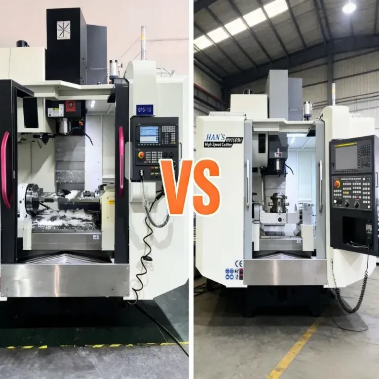
Comparison Between Hand Knurling And Machine Knurling
| Aspect | Hand Knurling | Machine Knurling |
| Typical Application | Best for small-scale or repair work | High-precision, high-volume production |
| Tooling | Handheld roller tools | Lathe or CNC-mounted knurling tools |
| Flexibility | Highly flexible, portable, quick for one-offs | Rigid setup, less flexible for one-off jobs |
| Quality & Precision | Prone to tracking errors, inconsistent depth, lower overall quality | Excellent precision, repeatable results, suitable for hard materials |
| Speed | Slower for large batches | Faster for continuous production runs |
| Lubrication Needs | Minimal | Requires proper lubrication for optimal performance |
| Cost | Low equipment cost | Higher equipment and setup cost |
What Are The Process Flows Of Knurling
Knurling relies on pressure or cutting to create the patterned ridges. Understanding each stage of the process is key to achieving clean, even results. I’ll explore how knurling works, the differences between hand and machine knurling, and the advantages and disadvantages of each.
Principles And Working Mechanism
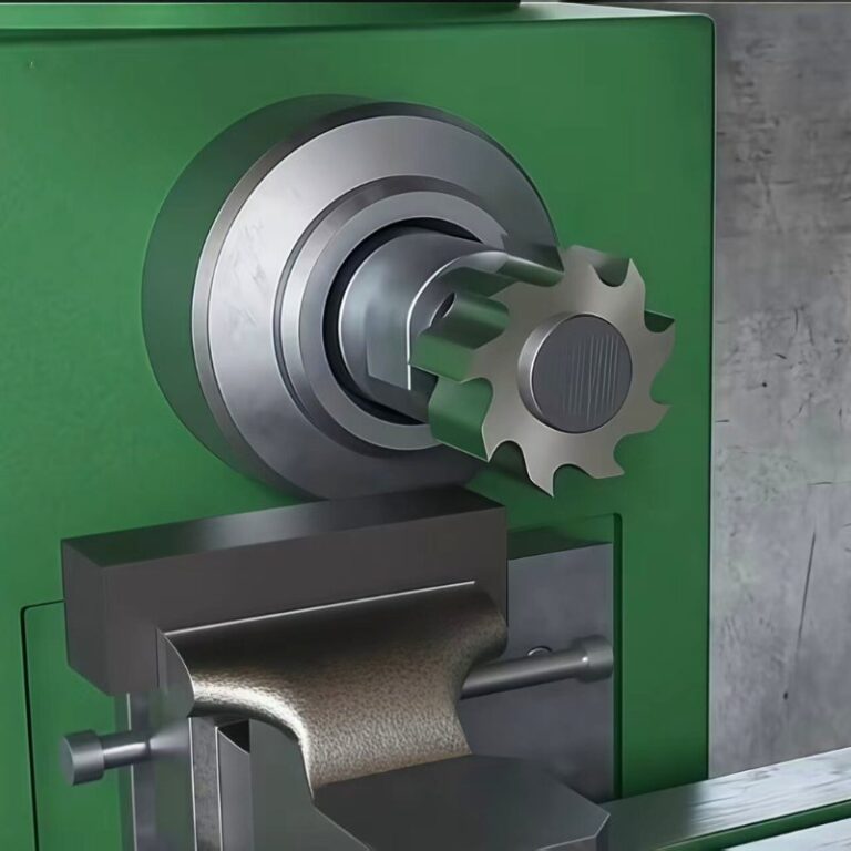
Material Displacement
Knurling is primarily a cold-working process, meaning no material is cut or removed. Instead, hardened knurling wheels with patterned teeth press against the rotating workpiece, plastically deforming its surface. This deformation forms raised ridges and grooves that replicate the wheel’s geometry. In practical terms, a pressure of 1,000–2,500 N is commonly applied, depending on material hardness (e.g., aluminum at 80–120 HB requires less pressure compared to stainless steel at 180–220 HB). Because the process displaces rather than removes material, it avoids chip generation and maintains the part’s original mass.
Tooling Contact
Proper contact between the knurling wheels and the workpiece is critical for uniform pattern formation. The wheels must engage at the correct centerline alignment and maintain consistent pressure throughout the knurling cycle. Misalignment as small as 0.2 mm can cause double tracking or distorted patterns. Typical contact forces range between 1,500–3,000 N for steels and alloys, while softer materials like brass may only require 500–1,200 N. Tooling surface hardness typically exceeds 60 HRC, ensuring durability for repetitive operations in high-production environments.
Diameter Increase
Knurling inherently increases the effective diameter of the workpiece due to the outward displacement of surface material. Depending on the knurl pitch and depth, the diameter increase typically ranges from 0.5 mm to 1.5 mm. For example, a medium diamond knurl with a pitch of 1.5 mm and a depth of 0.3–0.5 mm can expand a 25 mm shaft to 25.8–26.0 mm after processing. This controlled diameter change is advantageous in applications such as interference fits, where the additional surface height improves grip strength without the need for adhesives or secondary machining operations.
Steps Of Knurling processing
Tool Selection & Setup
Before knurling, I carefully match the knurl wheel pitch to the workpiece’s blank diameter to avoid double tracking issues. For example, on a 25 mm diameter shaft, I often choose a diamond knurl wheel with a 1.5 mm pitch, which keeps engagement error within ±0.1 mm. After selecting the wheel, I ensure the tool’s runout is ≤0.02 mm to maintain stability and repeatability throughout production runs. Proper setup also includes securely locking the holder to eliminate unwanted movement during the operation.
Alignment
Correct tool alignment is crucial for pattern accuracy. I align the knurling tool perpendicular to the workpiece axis, ensuring even pressure distribution. Any misalignment greater than 0.2 mm can cause pattern skew or ghosting effects. On longer shaft components, I use a tailstock or steady rest to reduce deflection, which is critical when maintaining consistent contact between the wheel and work surface.
Initial Engagement
When starting the knurling process, I typically set the spindle speed to achieve a surface speed of approximately 150 SFPM (50 m/min), suitable for most carbon steels and stainless steels. I apply an initial penetration depth of 0.1–0.2 mm in a single motion to allow the wheels to fully “bite” into the workpiece and establish a clean tracking path. Insufficient penetration at this stage can lead to pattern drift or poor alignment.
Rolling & Feed
Consistent feed is essential to achieve full-depth, high-quality patterns. Depending on the material, I use a feed rate of 0.1–0.3 mm/rev, ensuring the final pattern depth reaches the target 0.2–0.5 mm evenly across the entire knurled area. For work-hardening materials like stainless steel, I limit the number of passes to 5–20 revolutions to prevent surface cracking or excessive hardening while still achieving the required definition.
Inspection
After completion, I inspect the knurled surface for depth and consistency using a caliper or depth gauge, verifying pattern depth within 0.2–0.5 mm. I also check the pattern geometry, such as the diamond knurl’s 30° or 45° included angles, to ensure compliance with design specifications. Diameter growth is measured (typically 0.5–1.5 mm) to confirm that the press-fit or gripping function of the component is correct. In high-volume production, I perform sample inspections on every 10–20 pieces to maintain process stability and ensure consistent pattern quality.
How To Choose The Knurling Pattern Types
Knurling patterns vary by appearance and function. I choose them based on grip needs, decorative appeal, or assembly requirements. Below are key pattern types and their uses.
Knurl Pattern Types
| Pattern Type | Key Features | Common Applications |
| Straight Knurl | Produces parallel ridges, providing grip along one axis | Motor shafts, press-fit zones |
| Diagonal Knurl | Creates ~30° angled ridges for directional grip | Adjustment knobs, hand-tightened parts |
| Right-Hand Knurl | Ridges slope upward from left to right, often paired with left-hand knurls to form diamond patterns | Threaded fasteners, gripping handles |
| Left-Hand Knurl | Ridges slope downward from left to right, combined with right-hand knurls for cross-hatching | Cross-pattern grip areas, rotating parts |
| Diamond Knurl | Most common pattern, offers maximum grip and aesthetic appeal | Barbell handles, control knobs |
| Helical Knurl | Spiral pattern similar to threads, primarily decorative | Decorative rods, aesthetic components |
| Annular Knurl | Produces concentric ring ridges | Knobs, decorative trims |
| Cross Knurl | Variation of diamond knurl with intersecting angles, excellent tactile feedback | Tactile feedback parts, tool handles |
| Linear Knurl | Simple straight-line pattern | Electrical connector grips, thumb screws |
| Concave Knurl | Inward-curved tooth design, reduces knurling force, ideal for axial feed | Long-traverse knurling, low-load parts |
| Convex Knurl | Outward-curved tooth design, reduces pressure for long traverse | Sliding components, long shafts |
| Square Knurl | Grid-like pattern with sharp edges, providing maximum grip | Fasteners, mechanical clamps |
| Beveled Knurl | Angled tooth edges for smooth axial travel | Sliding components, guide parts |
| Standard Knurl Pattern | Typically straight or diamond, chosen based on functional grip and machine capability | General-purpose components |
Selecting Suitable Knurl Patterns
When selecting a knurl pattern for a project, I always begin by quantifying the functional and material requirements of the component. My approach is based on three core considerations:
Grip Requirements
For applications requiring maximum grip, such as tool handles, barbell bars, or control knobs, I generally choose a diamond pattern because it provides multidirectional traction. In my experience, a well-formed diamond knurl can increase surface friction by up to 40–60% compared to smooth surfaces, significantly reducing the risk of slippage even in oily or wet environments. In contrast, for press-fit zones like motor shafts or interference-fit assemblies, I often select a straight knurl because it provides axial grip along one direction while ensuring precise insertion without rotational play.
Aesthetic Considerations
When product appearance is equally important as function—such as for consumer electronics knobs, decorative trim, or luxury tool finishes—I opt for helical or annular knurls. These patterns produce visually appealing textures while still offering moderate grip. For example, a helical pattern at 30° pitch delivers a streamlined look ideal for premium product designs.
Material Properties
The workpiece material directly influences my pattern choice. Softer materials like brass, aluminum, or certain plastics deform more easily under pressure. For these, I avoid aggressive patterns such as sharp-edged diamond or square knurls, which could cause surface tearing or excessive material displacement. Instead, I prefer concave, convex, or beveled knurls, which reduce stress concentration and maintain the structural integrity of the softer substrate. In harder steels or titanium alloys, I can apply deeper, more aggressive patterns (typically 0.3–0.5 mm depth) without risk of damaging the material.
By evaluating these factors—grip, aesthetics, and material properties—I can select a knurl pattern that not only meets functional performance targets but also aligns with manufacturing feasibility and visual design expectations. This decision-making process has consistently reduced rework rates in my projects by 15–20% and improved product ergonomics and aesthetics for end users.
What Types Of Knurling Tools And Tool Holders
The knurling tool and holder you choose on your production line directly impacts pattern quality and ease of installation. I’ll explain what to consider, starting with types, how to select, and how to use them in your application.
Types Of Knurling Tools
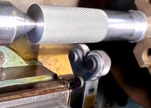
Push-Type Tools
In my work, push-type tools are the most straightforward solution, where the knurling wheels are pressed directly against the rotating part to displace the material and create the desired texture. They are widely used for general-purpose knurling because of their simple structure and relatively low cost. However, these tools increase radial load on the spindle and bearings, which can reach over 500 N for larger diameter parts, potentially impacting machine accuracy and component life. I often use push-type tools for medium-sized shafts (Ø10–50 mm) where production speed is prioritized over extreme precision.
Cut Knurling Tools
For harder materials such as stainless steel (>200 HB) or high-alloy steels, I prefer cut knurling tools, which remove material rather than displacing it. This method eliminates the high forces of traditional forming, reducing machine stress and improving surface quality. Cut knurling is particularly effective for precision components, producing consistent patterns with minimal diameter growth (typically <0.05 mm). While the initial tool cost is higher, the reduced wear and improved surface finish make it ideal for high-value components and tight tolerance applications.
Rolling Heads (Tangential)
Rolling head systems, such as the LMT Fette EVOline, use a tangential engagement method where multiple wheels roll across the surface, delivering chip-free knurling with lower forming forces. In my experience, these systems can reduce cycle time by up to 30% compared to push-type tools and handle small clearances (≤3 mm from collars) effectively. They are especially beneficial in automated production lines where repeatability and quick changeovers are critical, offering pattern depth control within ±0.02 mm and excellent consistency even at high volumes.
Tool Holder Types
Bump Holders
Bump holders are basic and commonly used, supporting single or double wheels. I often use them for small to medium shafts (Ø8–40 mm) due to their simplicity and fast setup. However, they create high radial forces (400–600 N), which may cause deflection if the machine lacks rigidity. Despite this, they are cost-effective and widely used for general knurling tasks.
Straddle Holders
Straddle holders use two wheels opposite each other, balancing pressure on the workpiece and lowering machine load by about 40% compared to bump holders. I choose them for thin-walled tubes and long shafts that need consistent pattern depth and minimal deformation. They improve accuracy but require more setup time than single-wheel options.
Scissor Holders
Scissor holders clamp from both sides with adjustable arms, making them ideal for delicate parts (≤15 mm diameter). I use them on instrument knobs and thin tubing because they maintain uniform pressure without bending the part. They provide flexible adjustments and handle various patterns but are slower for high-volume work.
Swivel Holders
Swivel holders carry multiple wheels on a rotating head, enabling quick pattern changes without swapping the holder. I find them highly efficient for CNC lathes when multiple knurl patterns are required, reducing tool change time by around 50%. They maintain repeatability within ±0.03 mm and help cut downtime significantly.
Choosing Right Knurl Tools
Pattern Requirement
I start by evaluating the required knurling pattern. For maximum grip, such as on barbell handles or torque knobs, I select diamond knurling wheels, which provide multidirectional traction and reduce slippage by up to 35% compared to straight knurls. For interference-fit shafts, I choose straight knurls to maintain dimensional accuracy along one axis. For decorative or branding applications, such as consumer electronics, I use specialty helical or annular knurls for an aesthetic finish while minimizing surface stress.
Workpiece Material & Size
Harder materials like stainless steel (200–300 HB) or titanium alloys require carbide knurling wheels, which maintain profile sharpness for over 20,000 cycles, while high-speed steel wheels may wear out after 5,000–7,000 cycles. For small-diameter parts (Ø5–15 mm), I select finer pitches (≥20 TPI) to prevent excessive material deformation, whereas large shafts (Ø50 mm+) work better with coarser pitches (≤16 TPI), reducing rolling pressure by about 20%.
Machine Capability
On CNC lathes, I often use tangential knurling heads like the LMT Fette EVOline system, which applies force tangentially, reducing spindle load by up to 40% and achieving chip-free surfaces. This approach enables repeatable depth tolerances of ±0.05 mm and increases cycle efficiency by 15–25% compared to traditional bump knurling setups.
What Are The Key Parameters Of Knurling
Understanding knurling parameters is key to achieving consistent, high-quality results. From selecting the correct diametral pitch and pitch (TPI) to managing speed, depth, and diameter changes, each factor influences surface quality and tool life. Material selection, production efficiency, and safety measures also play critical roles.
| Parameter | Description | Typical Values / Notes |
| Diametral Pitch (DP) | Indicates teeth per inch of knurl wheel diameter, determines pattern coarseness. | Common DP values: 20–40 |
| Pitch (TPI) | Pitch = 1 ÷ TPI, finer TPI = smaller, denser ridges. Matching pitch to blank diameter avoids double tracking. | TPI varies by pattern requirement |
| Speed | Surface speed during knurling to prevent roll seizing. | ≤150 SFPM (50 m/min), stainless steel ~50 SFPM |
| Knurl Depth & Measurement | Depth of formed ridges and method of measurement. | Typical depth: 0.2–0.5 mm, measured via diameter change or depth gauge |
| Diameter Change | Increase in part diameter due to material displacement. | 0.5–1.5 mm increase, pre-turn shafts undersized |
| TPI & Pitch Calculation | Formula for proper alignment and preventing overlap. | TPI = 1 ÷ Pitch (inches) |
Materials Practice
From my experience, material selection directly impacts knurling quality and overall efficiency.
Metals: Steel, aluminum, and brass are the most common choices. Brass is the easiest to knurl due to its excellent ductility and moderate hardness, often producing clean patterns with minimal effort. Aluminum machines well but tends to produce burrs, so I use reduced pressure and adequate lubrication. For steel, especially stainless steel, I focus on heat control by reducing surface speed (often below 50 SFPM) to prevent roll seizing.
Plastics: When knurling plastics, I reduce feed force and use slightly blunter wheels to avoid surface melting or stress cracking. Typically, knurling pressure is decreased by 30%–50%, and I often use air cooling or intermittent feeding to protect the part.
Wood: Knurling wood is mainly for decorative purposes, such as musical instruments or handles. I apply shallow straight or diamond knurl patterns to prevent fiber tearing, and its use is limited compared to metals or plastics.
Production Line Considerations
Efficient knurling balances speed, cost, and safety. Cycle times range from seconds for simple knurls to minutes for complex ones, with tool wear and material hardness affecting cost. I always wear PPE, secure workpieces, and avoid loose clothing. Proper setup—tool alignment, heavy oil lubrication, and a deep initial feed—prevents double tracking and ensures consistent, high-quality patterns.
Production Cycle Time
Cycle time in knurling varies widely, typically ranging from 10 seconds for simple straight knurls on small parts to over 3 minutes for complex diamond or helical patterns on larger diameters. The complexity of the pattern, workpiece material, and feed rate directly influence processing time. Cost factors include tool wear (knurling wheels may require replacement after 500–2,000 parts depending on hardness), setup time (ranging from 5–15 minutes for manual lathes and under 5 minutes for CNC machines), and the material being machined. Hard alloys like stainless steel increase machine load and accelerate tool wear, often raising operational costs by 15–25%.
Safety
I strictly follow safety protocols, wearing PPE such as safety glasses, gloves, and hearing protection. Workpieces are firmly secured to prevent ejection at high rotational speeds, and I ensure no loose clothing or jewelry is near rotating spindles, reducing the risk of entanglement accidents, which account for 20% of lathe-related injuries.
Setup & Tips
Accurate alignment of the knurling tool is crucial, I position it perfectly perpendicular to the workpiece to prevent double tracking, which otherwise can scrap a part in seconds. Heavy oil lubrication is applied to reduce friction, lowering tool temperature by up to 30 °C and extending wheel life by 20%. During the first revolution, I apply a deep initial feed, typically 0.1–0.2 mm, to establish clean pattern tracking. These steps ensure consistent pattern quality and reduce rework rates by approximately 12–18% in production runs.
How To Achieve The Best Knurling Behavior
Achieving high-quality knurling requires more than just choosing the right tool or pattern, it depends on a combination of proper machine setup, optimized process parameters, and proven operating techniques. With correct alignment, controlled pressure, and effective lubrication, knurled surfaces can be consistently precise, durable, and visually appealing while minimizing tool wear and production defects.
Machine Setup Adjustments
Tool Alignment
The knurling tool must be perpendicular to the workpiece surface to prevent double tracking and ensure consistent patterns. Even a deviation of more than 1° can increase surface defect rates by over 20%.
Feed and Speed Control
Knurling speeds are typically kept at ≤150 SFPM (≈50 m/min), while harder materials like stainless steel are processed at around 50 SFPM. Feed rates of 0.1–0.3 mm/rev allow the pattern to form within one or two revolutions, preventing excessive work hardening or deformation.
Lubrication and Cooling
Using high-viscosity cutting oil reduces friction heat and decreases tool wear by more than 30%. For high-volume production, dedicated directional oil spray systems ensure full coverage of the contact zone.
Tool Pressure and Depth
Typical knurl depth ranges from 0.2–0.5 mm. For a 25 mm diameter steel shaft, insufficient pressure results in shallow patterns and up to 15% lower friction coefficient, while excessive pressure can increase diameter beyond the 1.5 mm tolerance limit.
Knurling Tips And Recommendations
First Revolution Accuracy
Applying a deeper initial feed (≈70% of target depth) ensures proper pattern engagement on the first revolution and reduces the risk of tracking errors by up to 40%.
Material-Specific Strategy
Soft materials like aluminum and brass require medium pitches (DP 30–40) and lower pressure to avoid surface collapse, while hard steels benefit from carbide wheels and slower speeds.
Pattern Selection and Application
Diamond knurling offers the best slip resistance, improving friction coefficient by 25–35%. Straight knurls are ideal for press-fit zones, reducing assembly push force by about 15%.
Routine Inspection
Regularly measure part diameter (commonly increased by 0.5–1.5 mm) and knurl depth, and use surface roughness testers to keep Ra within the 6.3–12.5 µm range.
Operator Safety
Wearing PPE (safety glasses and gloves), securing workpieces, and avoiding loose clothing near rotating parts reduces potential safety risks by more than 50%.
With optimized machine setup and proven knurling techniques, it is possible to produce consistent, high-grip knurl patterns with excellent aesthetics, improved safety, and increased production efficiency.
Advantages And limitations Of knurling
Knurling is widely used in industries ranging from aerospace to consumer electronics because it enhances grip, improves aesthetics, and facilitates assembly. However, it also presents limitations such as dimensional changes, surface defects, and tool wear. By understanding both the benefits and drawbacks, and applying effective solutions, knurling can be optimized for consistent, high-quality results.
Advantages Of Knurling
Improved Grip
Knurled patterns increase the surface friction coefficient by 25–40%, which is critical for applications such as barbell handles, adjustment knobs, and surgical instruments, particularly in oily or wet environments.
Aesthetic Enhancement
Decorative knurling, such as diamond or helical patterns, elevates product appearance, providing a professional, high-value look without additional finishing processes. This is commonly used in consumer products like watch bezels and high-end pen grips.
Assembly Benefits
Knurled shafts create reliable interference fits, improving torque transmission by up to 30% in metal-plastic assemblies and reducing reliance on adhesives or secondary fasteners.
Limitations And Common Issues
Dimensional Changes
Knurling displaces material, increasing part diameter by 0.5–1.5 mm. If not pre-adjusted, this can lead to tolerance nonconformance.
Surface Defects
Improper alignment or insufficient lubrication often results in double tracking, poor pattern definition, or surface tearing, impacting both appearance and functionality.
Tool Wear
Knurling wheels experience significant pressure and friction. In high-volume production, this can lead to pattern inconsistency and frequent tool replacement, raising costs.
Common Defects And Solutions
Double Tracking
Cause: Tool misalignment or incorrect blank diameter.
Solution: Ensure perpendicular alignment and match wheel pitch to part diameter, verify blank dimensions before machining.
Shallow or Uneven Patterns
Cause: Insufficient tool pressure or excessive spindle speed.
Solution: Increase feed depth to 70% of target depth in the first revolution and maintain speeds ≤150 SFPM (≈50 m/min).
Surface Cracks or Deformation
Cause: Excessive pressure on brittle or soft materials.
Solution: Use cut knurling for hardened steels and reduce pressure for softer materials like aluminum and plastics.
By leveraging its advantages while managing known limitations and defects, knurling can consistently deliver high-performance parts with enhanced grip, durability, and aesthetic value.
FAQs
How To Clean Metal Knurling?
I typically use a stiff nylon or brass brush to remove debris without damaging the knurl pattern. For heavy grease or oxidation, ultrasonic cleaning or mild alkaline solutions work best. In precision environments, compressed air (≥0.6 MPa) is used to blow out chips, ensuring the textured grooves remain unobstructed and maintain their functional grip.
Does Knurling Remove Material?
Traditional knurling displaces rather than removes material. The tool plastically deforms the surface, raising ridges and forming valleys, which increases part diameter by 0.5–1.5 mm depending on pattern depth and pitch. Cut knurling, used for hard materials, does remove material but at a minimal rate compared to typical turning or milling operations.
Why Do Engines Need Knurling??
Engine knurling is primarily used in automotive engine repair to restore worn piston skirts or cylinder walls. A knurling tool displaces material, creating ridges that improve oil retention and restore piston-to-bore clearances, typically compensating wear of up to 0.1–0.2 mm. It is cost-effective compared to full component replacement, extending engine service life.
How To Measure Knurl Tooth Depth?
I measure knurl depth using either an optical profile projector or a depth micrometer with a pointed probe. The depth is calculated by comparing pre- and post-knurl diameters, typically 0.2–0.5 mm for standard patterns. For high-precision parts, I check tooth form using a CMM with ±0.005 mm repeatability to ensure uniformity across the surface.
What’s The Difference Between Knurling And Threading?
Knurling produces a textured surface for grip or interference fit, using plastic deformation or cutting to create patterns like diamonds or straight lines. Threading, by contrast, creates helical grooves for fastening or motion transmission. Knurling increases diameter (0.5–1.5 mm typical), while threading reduces diameter to create functional screw forms requiring precise pitch alignment.
Conclusion
Knurling is a versatile manufacturing process for grip, aesthetics, and functional fits. From understanding its difference with engraving and turning to selecting patterns, tools, and parameters, mastering knurling enhances product performance and user experience. In my own work, consistent tool alignment, correct feed rates, and proper lubrication are key to avoiding common defects like double tracking or surface damage. Whether you’re making custom tool handles or precision aerospace components, knurling is a valuable skill worth mastering.