GD&T Symbols represent a standardized system used in engineering drawings to control allowable variation in part geometry. These symbols ensure parts fit, function, and assemble correctly in real applications. They are essential for maintaining precision and alignment in complex components.
In this guide, you will learn how GD&T Symbols ensure consistency and clear communication between design, machining, and inspection teams.
What Is GD&T?
GD&T (Geometric Dimensioning and Tolerancing) refers to a standardized system used in engineering drawings to define and control the allowable variation of part geometry. It uses symbols to specify how features should relate to each other, ensuring parts function correctly during manufacturing and assembly.
Unlike traditional tolerancing, which focuses mainly on size dimensions, GD&T controls the geometric relationships between features, including form, orientation, location, and runout. This allows engineers to define functional requirements more precisely rather than applying unnecessary tight tolerances.
GD&T is widely used in precision manufacturing industries such as aerospace, automotive, medical devices, and CNC machining. It helps ensure that parts produced in different batches or locations can still fit together and perform as intended.
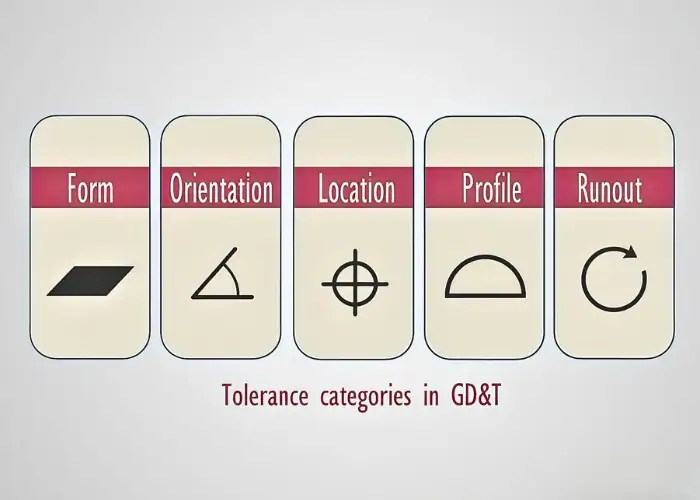
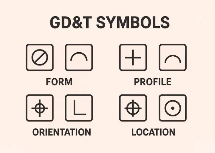
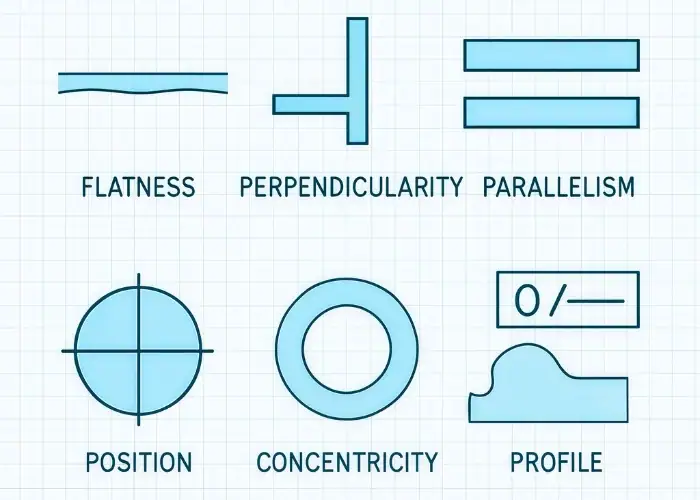
Typical GD&T controls include:
Form control – straightness, flatness, circularity, and cylindricity
Orientation control – parallelism, perpendicularity, and angularity
Location control – position, concentricity, and symmetry
Runout control – circular runout and total runout
Profile control – profile of a line and profile of a surface
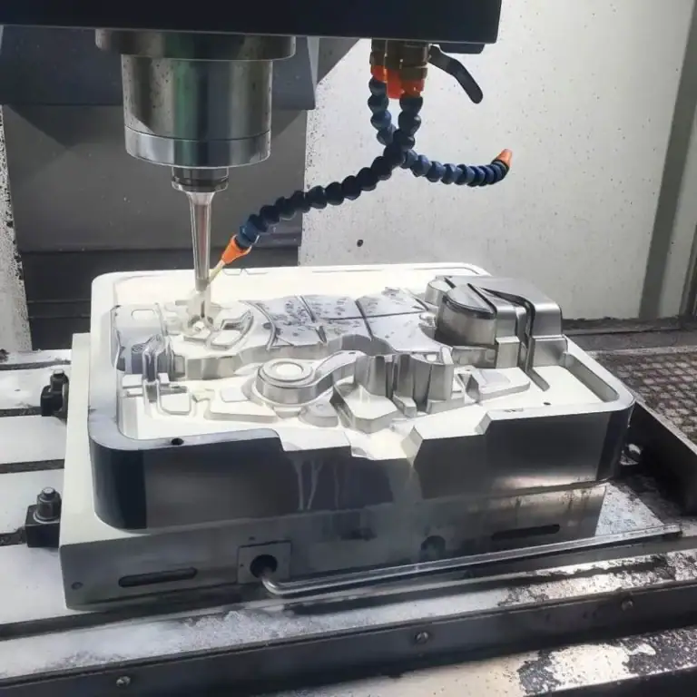
In modern manufacturing, GD&T is often integrated with digital tools such as CAD and CMM inspection systems. Engineers use CAD software to define tolerance requirements, while inspection tools verify whether parts meet the specified tolerance zones. This approach improves accuracy, reduces manufacturing errors, and ensures consistent quality in CNC machining production.
How GD&T Works in Engineering Drawings?
GD&T works by using symbols, datums, and tolerance zones to show how a part feature must behave, not just how big it is. This makes engineering drawings clearer and more functional, helping machinists, inspectors, and engineers understand exactly how a part should be made and checked during CNC machining and assembly.
1.Feature Control Frame
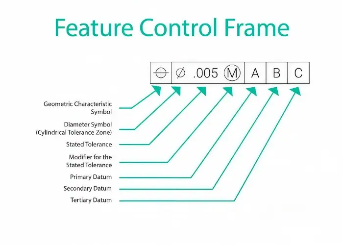
The Feature Control Frame, or FCF, is the main box used to show a GD&T requirement on an engineering drawing. It tells the reader what type of geometric control is being applied, how much variation is allowed, and which datums are used as references. In simple terms, it is the part of the drawing that explains how a feature must perform geometrically.
A typical FCF includes three key elements: the GD&T symbol, the tolerance value, and the datum references. For example, in ⌖ | Ø0.01 | A | B, the position symbol shows the type of control, Ø0.01 defines a cylindrical tolerance zone, and A and B show the datums used for measurement. This means the feature must stay within a 0.01 mm cylindrical zone relative to those references.
The FCF is important because it removes guesswork. Instead of relying only on plus-minus dimensions, engineers can clearly define how a hole, slot, surface, or axis must relate to the rest of the part. This improves machining accuracy, inspection consistency, and assembly performance.
2.Datum System
A datum system creates the reference framework used to measure and control part features. In GD&T, datums act like the fixed starting points from which other features are located and inspected. Without datums, it would be difficult to define where a feature should be or how it should align.
Most engineering drawings use three datums: Datum A, Datum B, and Datum C. Datum A is usually the primary reference and establishes the main contact surface or orientation. Datum B is the secondary reference and helps control rotation or alignment. Datum C is the tertiary reference and fixes the final position. Together, they create a stable coordinate system for manufacturing and inspection.
This system is valuable because it reflects how the part actually functions in real assembly. For example, if a bracket mounts to a base and aligns with a locating pin, the datums can represent those real contact features. That makes the drawing more practical and ensures the finished part fits correctly in use.
3.Tolerance Zones
Tolerance zones define the space within which a feature is allowed to vary. Instead of only saying a feature must be a certain size, GD&T defines the exact geometric boundary where that feature must remain. This makes part requirements more functional and easier to inspect.
Different GD&T controls create different tolerance zone shapes. Flatness usually creates a zone between two parallel planes. Position often creates a cylindrical zone. Circularity creates a zone between two concentric circles. These shapes are chosen based on how the feature needs to function in the final part.
Tolerance zones are especially valuable because they connect design intent to real manufacturing performance. They help engineers control how a part behaves in assembly, not just how it looks on paper. When tolerance zones are applied correctly, parts are easier to machine, inspect, and assemble with reliable and repeatable results.
GD&T Symbol Types Explained
GD&T symbols define how part features behave geometrically during manufacturing and assembly. By grouping them into clear categories, engineers can control shape, orientation, position, and motion, ensuring reliable performance and consistency in CNC machining.
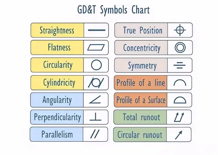
The table below summarizes the most common GD&T symbols used in engineering drawings:
| Category | Symbol | Name | Practical Definition | Typical Applications |
|---|---|---|---|---|
| Form | ─ | Straightness | Controls deviation of a line or axis to ensure it remains straight within a defined tolerance zone. | Shafts, guide rails, long edges requiring linear accuracy |
| Form | ⌔ | Flatness | Ensures a surface remains flat between two parallel planes without reference to a datum. | Sealing surfaces, base plates, mounting interfaces |
| Form | ○ | Circularity (Roundness) | Controls how close a feature is to a perfect circle at any cross-section. | Bearings, holes, rotating shafts |
| Form | ⌭ | Cylindricity | Controls the entire cylindrical surface to ensure consistent roundness and straightness. | Precision shafts, hydraulic components |
| Profile | ⌒ | Profile of a Line | Controls the shape of a 2D cross-sectional profile relative to the design intent. | Airfoils, curved edges, contour features |
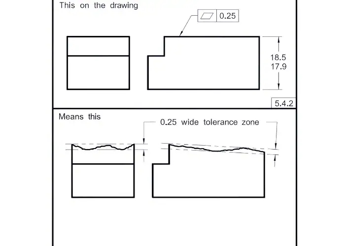
| Profile | ⌓ | Profile of a Surface | Controls the full 3D surface geometry across the entire feature. | Molds, complex surfaces, aerospace components |
| Orientation | ∥ | Parallelism | Ensures a feature remains parallel to a specified datum within a tolerance zone. | Sliding surfaces, guide systems |
| Orientation | ⟂ | Perpendicularity | Controls the 90° relationship between a feature and a datum. | Brackets, mounting faces, structural joints |
| Orientation | ∠ | Angularity | Controls a specific angle relative to a datum reference. | Tapered parts, angled surfaces |
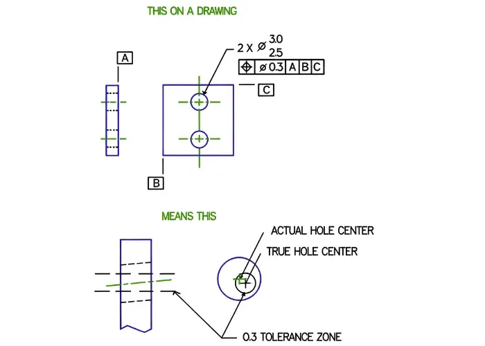
| Location | ⌖ | True Position | Defines the exact location of a feature relative to datums with high precision. | Hole patterns, pins, assembly alignment |
| Location | ◎ | Concentricity | Ensures multiple features share a common axis for rotational accuracy. | Rotating shafts, coaxial components |
| Location | ⌯ | Symmetry | Ensures features are evenly distributed about a datum plane. | Slots, symmetric parts |
| Runout | ↻ | Circular Runout | Controls variation of a feature during rotation at a single cross-section. | Shafts, rotating components |
| Runout | ⟲ | Total Runout | Controls the overall variation of a surface during full rotation. | Spindles, high-precision rotating parts |
Real GD&T Example in CNC Machined Parts
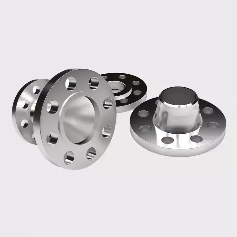
In real CNC machining, GD&T is used to ensure that parts not only meet dimensional requirements but also function correctly during assembly. A common example is a mounting plate with multiple holes that must align precisely with mating components to ensure proper fit, stable positioning, and reliable performance in the final assembly.

For instance, a hole may be defined with a position tolerance such as ⌖ Ø0.02 relative to datum A and datum B. This means the hole axis must remain within a cylindrical tolerance zone of 0.02 mm, ensuring accurate alignment during assembly. Without this control, even small deviations can cause misalignment, assembly difficulty, or mechanical failure.
This type of GD&T application is especially critical in precision parts where multiple components interact. By clearly defining geometric relationships, engineers ensure consistent fit, reduce rework, and improve overall machining reliability.
GD&T vs Traditional Tolerancing
Traditional tolerancing controls only size using plus-minus values, while GD&T defines how features relate in 3D space. This helps ensure proper fit, alignment, and function, making GD&T more reliable for CNC machining and complex assemblies where precision, consistency, and repeatable performance are critical.
1. Size Control vs Functional Control
Traditional tolerancing focuses on whether a dimension is within limits, but it does not guarantee how features interact. GD&T controls form, position, and orientation, ensuring parts not only meet size requirements but also function correctly when assembled.
2. Limited Definition vs Clear Design Intent
With traditional tolerancing, drawings can be interpreted differently by engineers and machinists. GD&T uses standardized symbols and datum references to clearly define how a part should behave, reducing confusion and improving communication across teams.
3. Tolerance Stack-Up vs Controlled Variation
Traditional tolerancing allows variations to accumulate across multiple dimensions, which can affect assembly performance. GD&T controls feature relationships, helping limit this effect and maintain consistent fit between parts.
4. Over-Tolerancing vs Efficient Manufacturing
Applying tight tolerances to all dimensions increases machining time and cost. GD&T allows engineers to tighten only critical features while relaxing others, improving machining efficiency and reducing unnecessary manufacturing expenses.
5. Basic Inspection vs Functional Inspection
Traditional inspection checks size only, which may not reflect real performance. GD&T defines tolerance zones, allowing inspectors to verify whether parts meet functional requirements, ensuring better quality and more reliable assemblies.
How GD&T Minimizes Accumulated Variation in Assemblies?
GD&T addresses this problem by defining geometric relationships relative to datums, rather than relying only on size dimensions. By controlling position, orientation, and form, GD&T ensures that critical features align correctly even when small variations exist.
For example, in a multi-hole assembly, controlling hole position relative to a datum prevents misalignment across parts. This reduces the risk of tolerance accumulation affecting final assembly performance.
By minimizing accumulated variation, GD&T improves product consistency, reduces assembly issues, and enhances overall manufacturing efficiency in CNC machining.
How GD&T Is Verified in Inspection and Quality Control?
GD&T is not only used in design but also plays a critical role in inspection and quality control. After machining, parts must be measured to ensure that all features fall within the defined tolerance zones, not just meet basic size dimensions. This ensures that parts will function correctly in real assembly conditions.
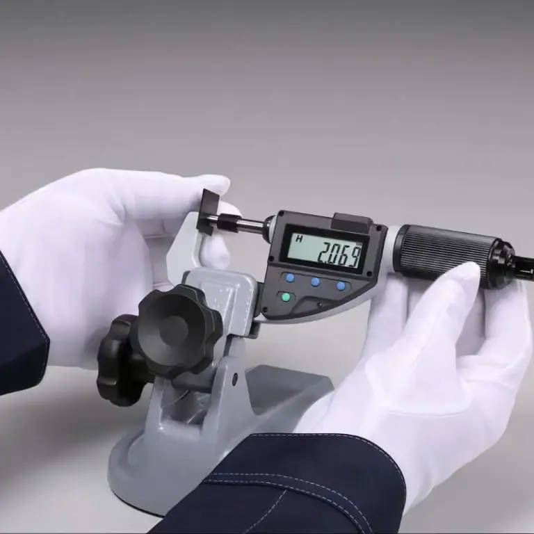
In CNC machining, inspection is typically carried out using advanced measurement tools such as CMM (Coordinate Measuring Machine), height gauges, dial indicators, and precision probes. These tools measure feature geometry relative to datums defined in the GD&T callouts. For example, a position tolerance is verified by checking whether a feature axis lies within a specified cylindrical tolerance zone.
Inspection based on GD&T focuses on functional accuracy rather than simple dimensional checks. Instead of measuring only length or diameter, inspectors evaluate how features relate to each other in space. This approach is especially important for complex parts with multiple interacting features, where alignment and orientation directly affect performance.
In addition, modern inspection processes often integrate digital systems. Measurement data from CMM machines can be compared directly with CAD models, allowing faster verification and more consistent results. This reduces human error and improves repeatability across different production batches.
By applying GD&T in inspection, manufacturers can reduce rejection rates, improve consistency, and ensure that parts meet both design intent and real-world functional requirements. This leads to higher product quality, better assembly performance, and more reliable CNC machining outcomes.
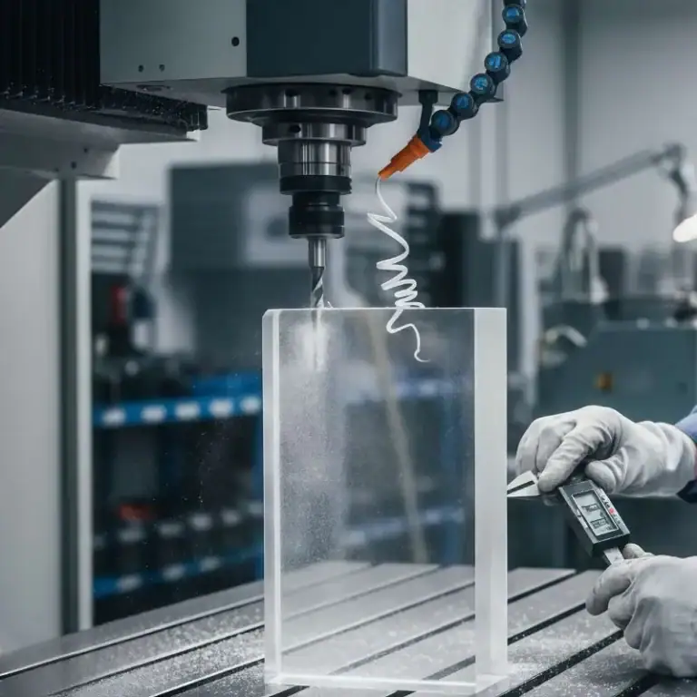
How Material and Machining Process Affect GD&T?
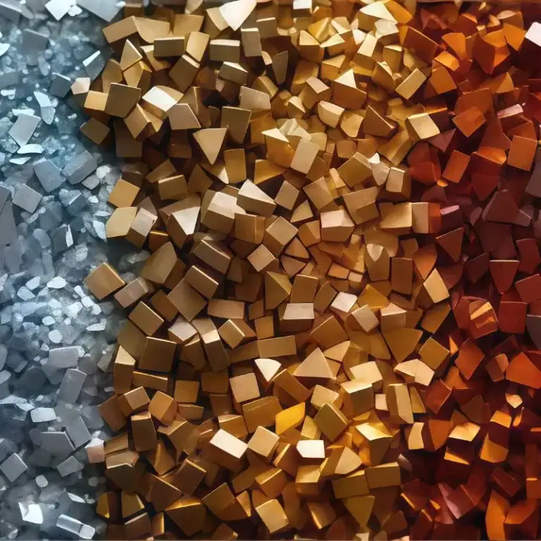
Material properties and machining processes directly influence how GD&T tolerances are achieved in real production. Different materials respond differently to cutting forces, heat, and tool interaction, which can affect dimensional stability, surface finish, and the ability to hold tight tolerances.
For example, plastics tend to soften or deform under heat, leading to dimensional changes during or after machining. Aluminum is easier to machine but may still deform if wall thickness is too thin. Stainless steel, on the other hand, generates more heat and causes faster tool wear, which can affect consistency and surface quality if cutting parameters are not optimized.
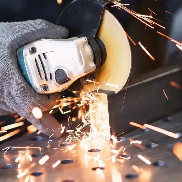
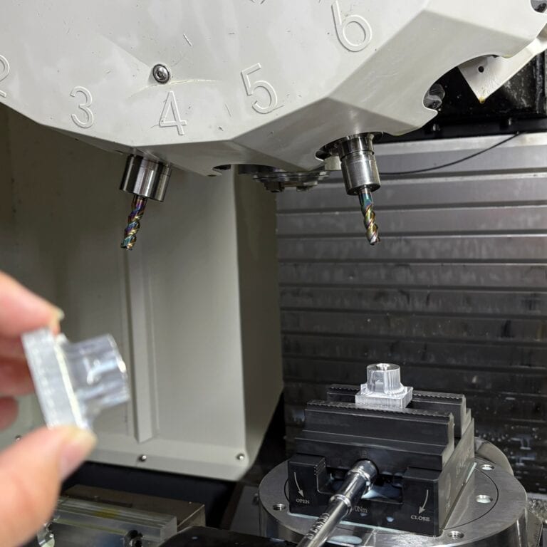
Machining processes also play a key role in achievable tolerances. CNC milling is suitable for general geometry but may struggle with ultra-tight flatness or perpendicularity. Turning provides better control for cylindrical features such as roundness and concentricity. Grinding and honing processes are often required when very tight tolerances or high surface finishes are needed.
In addition, factors such as tool selection, cutting speed, feed rate, and fixturing directly impact GD&T performance. Poor workholding can lead to vibration or movement, causing deviations in position or orientation. Thermal expansion during machining can also shift dimensions, especially in high-precision parts.
Engineers must consider both material behavior and machining capability when applying GD&T. Tolerances should be realistic and aligned with the selected process to avoid excessive cost or production difficulty. By balancing design intent with manufacturing constraints, it is possible to achieve accurate, stable, and cost-effective results in CNC machining.
How to Apply GD&T in Design?
Applying GD&T in design requires balancing functional performance with manufacturability. Instead of assigning tolerances based only on size, engineers should define how features interact in real use, ensuring parts can be machined efficiently while still meeting assembly and performance requirements.
1. Define Functional Surfaces as Primary Datums
The first step in applying GD&T is selecting the correct datum system. Functional surfaces such as mounting faces, sealing areas, or contact interfaces should be used as primary datums because they define how the part is positioned in assembly. Choosing non-functional surfaces can result in parts that pass inspection but fail in real use.
A well-defined datum system ensures that all critical features are aligned relative to real-world constraints. This improves assembly accuracy and reduces variation during both machining and inspection.
2. Apply Tight Tolerances Only to Critical Features
Not all features require high precision. Over-applying tight tolerances increases machining time, tool wear, and inspection complexity without improving performance. Engineers should identify which features directly affect fit, motion, sealing, or load transfer, and apply tighter GD&T controls only to those areas.
By relaxing tolerances on non-critical features, manufacturers can use faster machining processes and reduce cost while still maintaining functional performance.
3. Use Position Tolerance for Assembly Features
Position tolerance is one of the most important GD&T controls, especially for holes, pins, and mating features. It defines a tolerance zone that ensures features align correctly relative to datums. This is critical in assemblies where multiple parts must fit together precisely.
Proper use of position tolerance helps prevent common issues such as misalignment, interference, or uneven load distribution. It also simplifies inspection by clearly defining acceptable variation zones.
4. Avoid Over-Constraining Non-Functional Areas
Applying multiple GD&T controls or overly strict tolerances to non-functional features can create unnecessary complexity. This may lead to machining challenges, increased cost, and longer production cycles without adding value to the final product.
Engineers should evaluate whether each tolerance contributes to function. If a feature does not impact assembly or performance, it should be given reasonable tolerance limits to improve manufacturability.
5. Consider Machining Capability During Design
GD&T requirements must be realistic and aligned with actual CNC machining capabilities. Factors such as material type, tool selection, machine precision, and cutting conditions all influence achievable tolerances.
For example, tight flatness or position tolerances may require additional processes such as grinding or specialized fixturing. Understanding these limitations during design helps avoid costly revisions and ensures efficient production.
6. Align Design Intent with Inspection Methods
GD&T should always be defined in a way that can be measured accurately. Engineers must consider how features will be inspected using tools such as CMM, gauges, or manual measurement equipment.
If a tolerance cannot be easily measured, it may lead to inspection errors or inconsistent results. Designing with inspection in mind ensures that quality control is efficient, repeatable, and aligned with the intended function of the part.
Advantages of GD&T
1.Improves Functional Design
GD&T enables engineers to design parts based on real functional requirements rather than simple dimensions. By controlling alignment, position, and orientation, it ensures components fit and operate correctly in assemblies, improving reliability and reducing design-related errors.
2. Reduces Unnecessary Tight Tolerances
GD&T focuses precision only on critical features instead of applying strict tolerances everywhere. This avoids over-specification, gives machinists more flexibility, and allows faster machining processes while still maintaining required functional performance.
3. Lowers Manufacturing Cost
By optimizing tolerance distribution, GD&T reduces machining time, tool wear, and the need for secondary finishing operations. This leads to more efficient production, shorter lead times, and significantly lower overall manufacturing costs.
4. Enhances Inspection Accuracy
GD&T defines clear tolerance zones, allowing inspectors to evaluate features based on function instead of size alone. This improves measurement consistency, reduces interpretation errors, and ensures reliable quality control across different inspection methods.
5. Supports Global Standardization
GD&T follows international standards such as ASME and ISO, making engineering drawings universally understood. This ensures consistent communication across global teams, enabling reliable production, inspection, and assembly in different regions.
Why GD&T Is Important in Manufacturing?
GD&T is important because traditional tolerancing often fails to control how parts function in real assemblies. It solves problems such as misalignment, tolerance stack-up, and unclear design intent by defining how features relate in three-dimensional space rather than only controlling size.
1. Prevents Assembly Misalignment
Without GD&T, parts that meet size tolerances may still fail to fit together correctly. GD&T ensures critical features are positioned and aligned properly, preventing assembly issues in complex or multi-component systems.
2. Controls Tolerance Stack-Up
In traditional tolerancing, small variations from multiple features can accumulate and lead to assembly issues. GD&T helps control how features relate to each other, reducing this effect and improving overall assembly reliability.
3. Eliminates Design Ambiguity
Engineering drawings without GD&T can be interpreted differently by designers, machinists, and inspectors. GD&T uses standardized symbols and datums to clearly define design intent, reducing misunderstandings across teams.
4. Aligns Design with Manufacturing Reality
GD&T helps engineers define tolerances based on how parts are actually manufactured and assembled. This prevents unrealistic requirements and ensures designs are practical for CNC machining processes.
5. Ensures Functional Performance
Most importantly, GD&T focuses on how parts work, not just how they measure. By controlling geometric relationships, it ensures parts perform correctly in real applications, not just pass dimensional inspection.
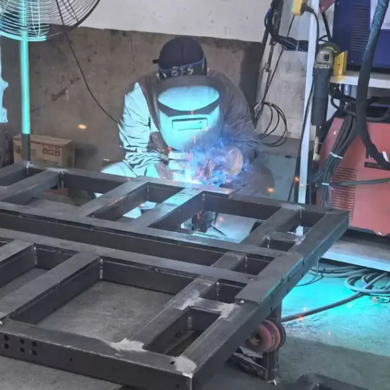
Applications of GD&T in CNC Machining
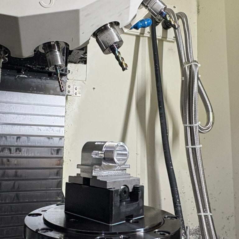
GD&T is widely used in CNC machining because it controls not only part size, but also how features relate to each other in real assembly and function. In practical production, it helps improve fit, reduce batch variation, and maintain stable quality across different industries where precision, repeatability, and functional alignment are critical.
1. Over-Constraining Non-Critical Features
One of the most common mistakes is applying tight tolerances to every feature, regardless of its functional importance. This increases machining time, tool wear, and inspection difficulty without improving actual part performance. In CNC machining, unnecessary tight tolerances may require additional finishing operations or specialized tooling.
Engineers should identify which features directly affect assembly or function and apply stricter GD&T controls only to those areas. Non-critical features can be given wider tolerances to improve manufacturability and reduce cost.
2. Incorrect Datum Selection
Choosing the wrong datum can lead to incorrect measurement references and poor assembly alignment. Datums should represent how the part is positioned in real use, such as mounting surfaces or functional contact points. Using non-functional or unstable surfaces as datums can result in parts that pass inspection but fail during assembly.
A good datum system reflects real-world constraints. For example, if a component is mounted on a base, that base surface should typically be the primary datum. This ensures that all controlled features align correctly during actual operation.
3. Misusing Position Tolerance
Position tolerance is one of the most powerful GD&T tools, but it is often misapplied. Engineers sometimes use position tolerance without properly defining datums or without understanding how the feature interacts with other components. This can lead to overly restrictive requirements or unclear inspection results.
To use position tolerance effectively, engineers must clearly define datum references and ensure the tolerance zone matches the functional requirement. Proper application ensures accurate hole alignment, consistent assembly, and reliable performance.
4. Ignoring Manufacturing Capability
Designing GD&T requirements without considering machining capability can create unrealistic tolerances that are difficult or expensive to achieve. For example, specifying extremely tight position or flatness tolerances may require high-end equipment, slower machining speeds, or multiple finishing operations.
Engineers should align GD&T requirements with actual CNC machining capabilities, including tooling limits, machine accuracy, and material behavior. This balance helps achieve functional performance without excessive cost or production delays.
5. Lack of Functional Understanding
Applying GD&T without understanding how a part functions in assembly is a fundamental mistake. Some designs include unnecessary or incorrect tolerances that do not contribute to performance, while critical features may be under-controlled.
GD&T should always be applied based on how the part interacts with other components. Engineers should consider load paths, alignment requirements, and motion constraints to ensure that tolerances support real-world function rather than theoretical design assumptions.
FAQs
When should GD&T be used?
GD&T should be used when part function depends on precise geometric relationships, not just size. It is essential for assemblies requiring accurate alignment, fit, and motion between components.It is widely applied in CNC machining and high-precision industries to ensure consistency and interchangeability.
How Are GD&T Symbols Displayed in Drawings?
GD&T symbols are displayed using a Feature Control Frame (FCF), which includes the geometric tolerance symbol, tolerance value, and datum references. The FCF is connected to the feature with a leader line, making it easy for machinists and inspectors to understand how the feature should be controlled and measured.
What Are GD&T Symbols Used for in CNC Machining?
In CNC machining, GD&T symbols are used to control how features relate to each other, rather than just their size. They help improve machining accuracy, reduce errors, and ensure proper fit between parts. This is especially important in precision components where alignment and consistency are critical.
What Is the Position Symbol in GD&T?
The position symbol controls the exact location of features such as holes, pins, or slots relative to datums. It defines a tolerance zone within which the feature must remain, ensuring accurate alignment during assembly. It is one of the most important and widely used GD&T controls in machining.
What Is the Most Common GD&T Symbol?
The position symbol is one of the most commonly used GD&T symbols because it directly affects assembly accuracy. It is frequently applied to hole patterns, mounting features, and alignment components, ensuring parts fit together correctly even when small variations occur.
Conclusion
Understanding GD&T symbols and their meanings helps engineers design parts that are easier to manufacture, inspect, and assemble.
When applied correctly, GD&T improves precision, reduces errors, and ensures consistent performance. It also enhances reliability across CNC machining processes and complex assemblies.
At TiRapid, we specialize in turning complex GD&T drawings into high-precision CNC machined parts. With strict quality control and advanced inspection systems, we ensure every part meets your exact requirements.