What Is A Blind Hole?
In my experience in precision parts processing, blind holes are a frequently encountered but easily underestimated structural design. Blind holes are not “invisible” holes, but holes that are only open on one side and do not penetrate the entire workpiece, and the bottom is closed. It is often used in fastener threaded holes, locating pin installation holes, air pressure control holes, etc., and is especially suitable for parts that cannot affect the structural integrity of the back.
From a design perspective, blind holes are more complex than through holes because they have strict requirements on depth, bottom shape, thread integrity, etc. For example, when machining a threaded blind hole with a diameter of M6, it is usually necessary to reserve an additional space of 1.5 times the pitch as a tapping buffer area. If sufficient depth is not reserved, it is easy to cause incomplete tapping or even broken taps.
Statistics show that the probability of blind holes making mistakes in mass production is about 20% higher than that of through holes. Common problems include chip retention, drilling deviation, uneven hole bottom or insufficient tapping depth. Therefore, although blind holes are small, they are the concentrated embodiment of design and processing precision control. Every reasonable design and stable processing of blind holes is a true test of manufacturing capabilities.
It usually only drills to a certain depth and does not penetrate the workpiece.
It is commonly used for screwing in screws, placing pins, ventilation, etc.
Compared with through holes, blind holes are more complicated to process and have less room for error.
The Difference Between Blind Holes And Other Holes
In many product structure design and parts processing projects I have participated in, the frequency of use of blind holes is almost the same as that of through holes, but the differences in structure and processing logic between the two are very significant. Blind holes refer to holes that are open only on one side and do not penetrate the entire material thickness, while through holes are completely penetrating holes; this structural difference directly affects their manufacturing methods, assembly applications and mechanical properties.
For example, during the tapping process, through-hole taps can be used, and the chips can be discharged smoothly from the bottom, greatly reducing the risk of wire breakage. Blind holes require the use of special spiral grooves or extrusion taps to ensure that the chips can be discharged upwards and do not block the bottom of the hole. According to our workshop data, if the chips are not removed in time during the processing process, the failure rate of blind hole tapping will increase to about 12%, which is much higher than the 5% of through holes.
In addition, blind holes are often confused with countersunk holes and stepped holes. Countersunk holes are holes with enlarged openings to allow the screw head to sink into the material. They are two-stage holes with a “large opening and small bottom” structure. Stepped holes, on the other hand, have two or more hole sections with different diameters in the axial direction and are suitable for assembling components with shaft shoulders or stops. Blind holes are usually single-size, bottom-closed structures that focus more on depth and axial concentricity control.
In general, blind holes have a lower tolerance for processing errors than other hole types, and issues such as chip removal, tapping depth, and hole bottom shape need to be considered during design. It is these seemingly detailed differences that determine the reliability and functional realization of the parts.
Which Industries Use Blind Vias
Blind holes are widely used because they can achieve fastening, positioning or ventilation functions without destroying the shape and structural integrity of the part. I have been exposed to the application of blind holes in projects in many industries, especially in the mold, automotive, aviation, medical and electronics industries.
The following is a classification description of several typical application scenarios:
| Industry Category | Application Scenario | Reasons for using blind vias |
| Mold manufacturing | Screw installation and guide column positioning for injection molds and die casting molds | Prevent penetration of the mold and avoid affecting the molding area |
| Automobile and aviation parts | Engine casing, connecting bracket, fuselage structure | Compact structure and fixed area, without affecting the overall strength |
| Medical Devices | Minimally invasive devices, threaded holes for implants | Precise positioning to avoid perforation affecting biocompatibility |
| Consumer Electronics | Mobile phone housing, camera module, sensor fixing point | Maintain appearance integrity and enhance structural stability |
These industries have high requirements for the reliability and compact structure of parts, and blind holes just meet their dual needs in function and design.
How Are Blind Holes Processed?
The processing method of blind holes is not the same for everyone, but is customized according to hole depth, precision and material properties. It is different from through holes, and cannot rely on the through structure to help chip removal and positioning. Therefore, when processing blind holes, I am most concerned about how to accurately control the depth, how to efficiently remove chips, and how to ensure the integrity of the bottom . Whether using CNC machine tools or manual equipment, the core goal is to ensure that the blind hole meets the required functional standards, especially in terms of error control within ±0.05mm and reliable chip removal.
Below I will disassemble the common processing methods and key control techniques in detail :
Common drilling methods and tools introduction
The processing method of blind holes depends on the requirements for accuracy and efficiency:
Hand drills are suitable for rough processing, but have poor precision and are mainly used in situations where assembly tolerances are not strict.
The bench drill is suitable for small and medium-sized parts. The depth can be manually controlled by a limiter and is suitable for general use in the workshop.
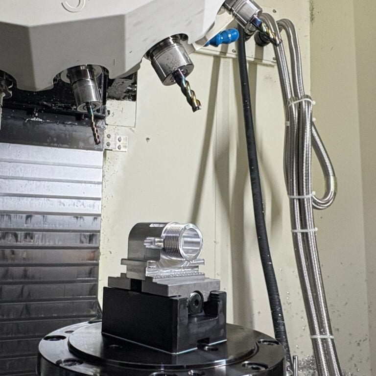
CNC drilling machines or CNC milling machines support automatic control of drilling depth, with a repeatability accuracy of up to ±0.02mm, making them the first choice for batch blind hole processing.
If the blind hole requires H7 or higher tolerance, we will use a reamer or boring tool for secondary processing to improve the inner wall quality and dimensional consistency.
How to control the drilling depth?
The key to blind hole processing is that the depth should not be too deep or too little.
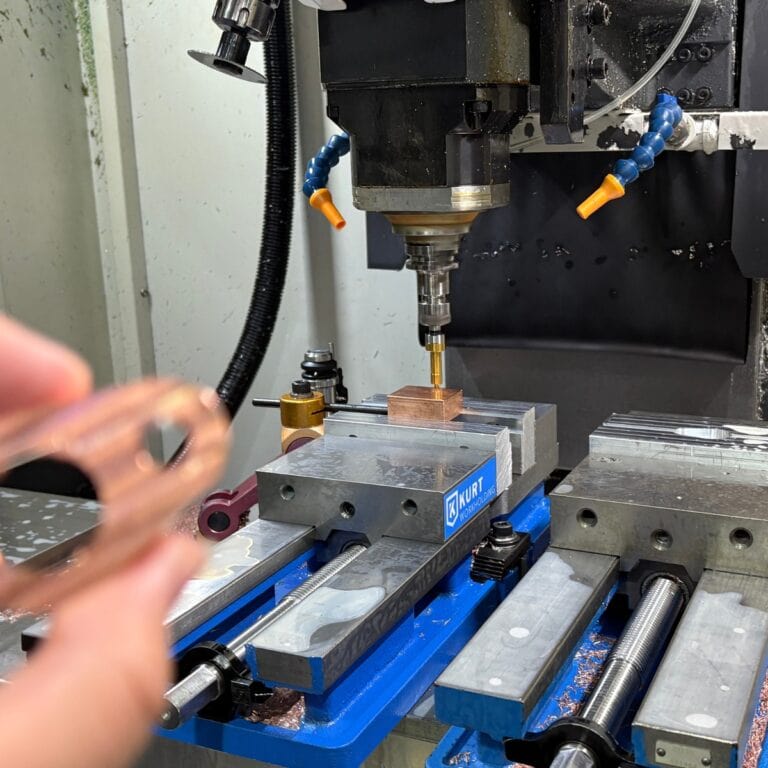
I usually use CNC machine tools to set the precise drilling depth. For example, if it is set to 10.2mm, the machine tool can execute it repeatedly and stably, and the error is controlled within ±0.05mm.
On non-CNC equipment, manual control is performed through limit rings, mechanical stops or the addition of a depth gauge. Although this is inefficient, it is suitable for low-cost occasions.
When processing non-metallic or soft materials, springback or local expansion must also be considered to prevent drilling through the bottom.
How to remove chips from blind holes?
The chips cannot naturally penetrate the bottom of the hole and be discharged, which is the most common processing problem of blind holes.
I usually use a spiral groove drill bit, which can roll the chips out along the groove and improve chip removal efficiency.
For deep blind holes (depth > 3x hole diameter), I would time the tool withdrawal during the drilling process and use coolant or high pressure gas to assist chip evacuation.
If chips remain at the bottom of the hole, it will cause the tapping to break or the subsequent assembly to be incomplete. Therefore, the chips at the bottom of the hole must be cleaned manually or with air blowing after each processing.
These seemingly basic treatments actually determine whether a blind hole can work stably in actual applications. They are the key points that I must strictly follow in every precision machining.
How To Tap A Blind Hole?
Blind hole tapping is much more complicated than through hole tapping. The key is not only to be able to “screw it in”, but also to be able to “screw it in” and not to break the tap easily. What I pay most attention to in actual processing is whether the tapping depth is strong enough, whether the tap is suitable for the blind hole, and how to ensure that the thread is intact and not easy to strip. Generally speaking, it is safer to design the effective engagement length of the thread to be 1 to 1.5 times the diameter of the screw. Blind holes cannot be penetrated, so the space for tapping is more limited, chip removal is difficult, and the wire is more likely to get stuck and break. At this time, the correct tap selection and processing method are crucial.
How to design the tapping depth to ensure firmness
When I design blind hole tapping, I usually make sure the effective thread engagement depth is at least equal to the diameter of the screw. For example, with an M6 screw, a minimum effective thread depth of 6mm is required, with an ideal range of 6–9mm.
If the structure allows, I would choose 1.2 times the depth as the standard to increase the connection strength.
However, you cannot just keep deepening the thread. If the depth exceeds 1.5 times, it will increase processing time and cost, and it will also make it easier for the tap to break or make chip removal difficult.
What are the special taps for blind holes?
For blind holes, I usually use a spiral groove tap or a bottom hole tap, which can carry the chips upward and avoid clogging the hole.
The larger the spiral groove angle, the stronger the chip evacuation ability, which is suitable for deep hole processing. But please note that their service life is slightly lower than that of straight groove taps.
Although straight groove taps have low costs, their chip removal direction is downward, which makes them unsuitable for blind holes and prone to breakage or incomplete threads due to poor chip removal.
On CNC machines, you can also use a forming tap (chipless) to form the thread by squeezing the material, which is particularly suitable for soft metal materials such as aluminum or brass.
Tips to prevent thread stripping
Before tapping, I will thoroughly clean the chips in the hole and check whether the bottom hole size is accurate. If it is too small, the thread will be stuck, and if it is too large, the tooth shape will be incomplete.
Lubrication is a key step, especially in the processing of steel or stainless steel parts, special lubricating oil for tapping must be used to reduce friction and temperature rise.
It is particularly important to control the feed rhythm when tapping by hand: every two turns, you need to backfeed half a turn to evacuate the chips and avoid the tap getting stuck.
When CNC tapping, it is important to set the appropriate feed rate and reverse speed to avoid the tap from hitting the bottom, especially in small holes (such as below M3).
In my opinion, blind hole tapping is not simply “screwing out threads”, but a process that is highly dependent on tap selection, processing parameters and chip removal control. Any error in any link may result in the scrapping of the workpiece or damage to the equipment.
What Should We Pay Attention To When Designing Blind Holes?
In the projects I participate in daily, the design of blind holes is often underestimated. In fact, although it is small, it has a profound impact on the assembly, strength and processing difficulty of parts. I often remind customers: blind holes are not as simple as “drawing a circle and digging a hole”. The processing allowance, hole layout and inspection requirements must be considered at the drawing stage. Especially in CNC precision machining, a blind hole error may directly lead to the scrapping of the entire workpiece. Reasonable design is the key to reducing later problems and improving assembly efficiency.
Leave some margin at the bottom of the hole, don’t drill through
In the drawings, I usually recommend leaving at least 0.5-1mm of material at the bottom of the blind hole, which not only prevents the drill from accidentally penetrating, but also improves the bottom strength.
For example, when processing a blind hole with a depth of 20 mm, set the drilling depth to 19 mm to ensure sufficient tolerance during operation.
Especially in tapping scenarios, 2-3 more teeth of space must be left at the bottom of the hole for the tap to rotate, otherwise the teeth will break or break.
Reasonable layout of hole positions and hole distances to prevent processing conflicts
If the blind holes are too close together, problems such as thin walls, weak structures or chip accumulation may easily occur during processing.
I usually set the hole center distance to be greater than twice the hole diameter. For example, the center distance of M6 blind holes should not be less than 12mm, which is conducive to chip removal and strength distribution.
In addition, the fixture fixation and tool feed path should be considered to avoid the design being too compact that makes CNC processing impossible.
Surface roughness, chamfer and tolerance requirements must be indicated
I often encounter customers whose drawings do not indicate tolerances, resulting in mismatches between the finished product and the assembly. It is recommended that the blind hole tolerance be controlled within ±0.05mm.
It is recommended that threaded holes be marked with standard specifications such as “M6x1 – 6H” to avoid processing misunderstandings.
If there is no special requirement for the chamfered part, it is generally set to 0.5×45° to avoid sharp edges that may injure people or cause assembly difficulties.
For holes that need to be sealed or precisely fitted, the roughness value (such as Ra1.6) should also be clearly specified to improve the assembly fit.
In general, designing a blind hole that is easy to use, easy to process, and easy to assemble is not only a reflection of the engineer’s sense of responsibility, but also directly affects the consistency of the product and customer satisfaction. Although the blind hole is small, it cannot tolerate any carelessness.
How To Detect The Size And Quality Of Blind Holes?
The dimensional accuracy and internal quality of blind holes directly affect the functional reliability of parts. In actual production, I have seen many cases where screws cannot be tightened, assembly is poor, or tapping fails due to inadequate measurement. Compared with through holes, blind holes are more difficult to measure and inspect, but as long as the right inspection tools and methods are mastered, it can be ensured that blind holes are both up to standard and stable. Especially in batch processing, whether the inspection process is standardized determines whether the yield can be controlled above 98%.
Commonly used depth measurement tools
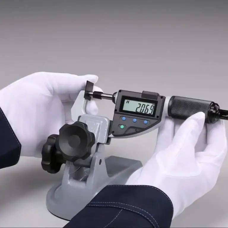
There are three tools I often use to measure blind hole depth: depth gauge, digital caliper, and coordinate measuring machine (CMM).
Digital calipers are the most common on-site tools, suitable for situations where the hole depth is less than 150mm and the accuracy requirement is ±0.1mm.
If the hole is deeper or higher accuracy (±0.01mm) is required, it is recommended to use a CMM or a depth gauge with fine adjustment function.
Some customers require that each batch of first-piece blind holes be inspected using three-coordinate measurement and a test report be issued to meet ISO quality system requirements.
Inspection method after tapping
After tapping is completed, I usually use a go/no-go gauge to check the threads, which is the most intuitive and reliable way.
The go gauge should be screwed in smoothly to the effective depth, and the stop gauge should not be screwed in more than 2 threads, otherwise it will be considered as having too large a thread.
For critical parts, I will also use thread ring gauges and torque wrenches to check to ensure that the bonding strength meets the design requirements.
Some precision parts (such as medical devices) also require an endoscope or small probe to check for debris at the bottom of the hole and processing burrs.
How to avoid common defects of blind holes
Tool dullness is the main cause of hole collapse and thread failure. I recommend checking drills and taps every 100-200 holes.
For deep hole tapping, I will set an appropriate chip removal frequency and use a high-pressure cooling system to remove chips to prevent hole blockage or tool breakage.
The setting of processing parameters is also critical, especially the feed speed and spindle speed. It is recommended not to pursue speed blindly, but to prioritize accuracy.
Automatic pause and chip removal instructions can be added to the CNC program to ensure that every blind hole is “clean, complete and qualified” after processing.
Blind hole detection is not just about size, it is also the last checkpoint to ensure the stable performance of the entire part. Rigorous design, precise processing, and standardized testing are required to truly make the blind hole “deep but not blind”.
What Are The Difficulties In Processing Blind Holes? How To Solve Them?
Although a blind hole looks like an “unpunched hole”, it is much more difficult to process than a through hole. I have encountered cases where the tool was stuck due to poor chip removal and assembly failed due to insufficient tapping depth, and the customer return rate soared instantly. In the final analysis, the most common source of problems with blind holes is that they are “invisible” and “unclearable”.
Here I will combine my experience to talk about the key difficulties and solutions of blind hole processing in three categories :
Problem of difficult chip discharge
The biggest problem is that the space in the blind hole is limited, and chips tend to accumulate at the bottom of the hole, causing heat accumulation and increased tool wear.
I recommend using a spiral groove drill or tap to automatically carry the chips upwards, and at the same time use high-speed coolant flushing or intermittent tool retraction to effectively reduce the probability of hole blockage.
When machining deep holes (such as depth > 3 times the diameter), multi-stage feeding is recommended , that is, drilling one section and retracting one section to ensure that the chips are discharged in time.
For non-metallic parts with blind hole depth exceeding 30mm, I will also use negative pressure chip extraction in combination with the chip removal function to improve chip removal efficiency.
Insufficient tapping depth
When designing drawings, many engineers only mark the total depth and ignore the effective engagement depth of the thread . As a result, the screws only bite twice during assembly and come loose as soon as they are tightened.
I usually confirm before processing: the effective thread depth ≥ 1.2 times the screw diameter (such as M6 screws, the thread depth is at least 7.2mm).
When processing, select a spiral groove tap and set the Z-axis depth and buffer distance in the CNC program to ensure that the tapping is complete without residual teeth.
The quality and bonding strength of blind hole threads can also be improved by **double tapping (rough tapping + fine tapping)**.
Solutions for drilling deviation and residual material at the bottom of the hole
Drilling deviation often occurs in small holes or hard materials, especially when the center drill is not used for positioning. I suffered a lot in the beginning, and now I insist on using the center drill for pre-positioning .
The choice of tool angle is also critical, and it is recommended to use a self-centering drill bit (such as a 135° sharp angle) to reduce deviation.
The problem of residual material at the bottom of the hole often occurs due to incomplete machining or chip rebound. I will set the bottom detection amount to 0.2mm more than the target depth to ensure that the bottom of the hole is clean.
a bottom hole probe re-inspection after processing or use a small milling cutter to clean the bottom residue.
Although blind hole processing is common, it hides many details: if the processing method is not selected correctly, the tool is easy to break; if the design size is not considered clearly, the assembly may be scrapped. Mastering the appropriate processing techniques and design specifications is an indispensable basic skill for every engineer.
Overview Of The Advantages And Limitations Of Blind Vias
| Classification | Contents |
| advantage | – Suitable for designs where the structure cannot be penetrated, such as sealed cavities, exterior surfaces, etc. – Saves space for parts and facilitates compact design – Improves structural strength and avoids damage to integrity |
| limit | – High processing difficulty, depth accuracy needs to be controlled – Difficult chip removal, easy to cause tool jam – Low fault tolerance, easy to cause scrapping due to deviation |
Practical Advice For Engineers
| stage | Suggested content |
| Before design | – Specify whether it is a blind hole and determine its function (fastening, positioning or ventilation) – Set the thread depth requirement, generally 1-1.5 times the screw diameter |
| Processing | – Use special tools (such as spiral groove taps) – Use coolant or intermittent chip removal – Control speed and feed to avoid drilling deviation |
| Inspection stage | – Use tools such as depth gauge, go/no-go gauge, CMM to check item by item – Do not omit any inspection steps, especially thread accuracy and hole depth |
FAQs
What Is A Blind Hole Tap?
A Blind Hole Tap Is A Specialized Tool For Threading Non-Through Holes.
I use bottoming taps or spiral-flute taps for blind holes. They allow full thread cutting close to the bottom without damaging the hole. Bottoming taps typically engage 1–2 threads early and are essential when the full thread length must be achieved in tight spaces.
What Is The Difference Between A Thru Hole And A Blind Hole?
A Thru Hole Goes Entirely Through A Part, While A Blind Hole Stops At A Defined Depth.
In my daily work, I use thru holes when bolts or pins must pass completely through. Blind holes are chosen when structural integrity or aesthetics require the back surface to remain untouched. Blind holes are harder to machine and inspect, especially when deeper than 3× diameter.
What Is The Blind Hole Method?
The Blind Hole Method Refers To Controlled Machining And Threading Of A Non-Penetrating Hole.
In practice, I first calculate the required depth (thread engagement + clearance), then use CNC depth control or stops. I apply spiral drills and reamers for finish, followed by chip-evacuating taps. For example, tapping M6 in blind holes requires 5.0 mm predrill and precise 10 mm thread depth.
How To Measure A Blind Hole?
Blind Hole Depth Is Measured Using Depth Gauges, Calipers, Or Coordinate Measuring Machines.
I prefer digital depth calipers for fast checks or CMM for ±0.01 mm accuracy. For threaded holes, I confirm thread depth using go/no-go gauges. For high-precision blind holes, consistent tool wear and clean internal surfaces also affect true depth accuracy.
How To Pull Bearing From Blind Hole?
To Pull A Bearing From A Blind Hole, Use An Internal Bearing Puller Or Slide Hammer Tool.
I typically insert a blind bearing puller with expanding jaws inside the bearing ID. Once tightened, a slide hammer helps extract it without damaging the housing. For tight tolerances, I preheat the housing to 60–80°C to reduce friction before removal.