What is Rapid Prototyping? It’s the fastest way to bridge the gap between ideas and real products. By leveraging CNC machining, 3D printing, injection molding, and vacuum casting, you can validate concepts quickly. This guide shows how rapid prototyping saves time, reduces cost, and speeds up product launches.
What is Rapid Prototyping
Rapid prototyping (RP) bridges the gap between idea and product. Unlike traditional prototyping that is slow and expensive, RP uses technologies like 3D printing and CNC machining to build models in hours, not weeks. It’s faster, cheaper, and perfect for testing, communication, and customization—helping you launch better products, sooner.
What’s The Differences Rapid Prototyping And Traditional Prototyping
Traditional prototyping often requires expensive tooling and long lead times. Rapid prototyping (RP), on the other hand, uses digital manufacturing like 3D printing and CNC machining to produce models in hours or days. This shortens development cycles and reduces costs dramatically.
Why Use Rapid Prototyping
RP helps teams bring designs to life quickly, validate functionality, and reduce risks before mass production. It saves cost, speeds up iterations, improves communication with stakeholders, and enables customization. These benefits make RP essential for modern product development.
What Processes Does Rapid Prototyping Go Through
The rapid prototyping process covers goal setting, prototype iteration, phased validation, and testing. It starts with defining objectives and constraints, then moves through build–review–refine cycles, advancing to concept, appearance, function, and engineering validation. Finally, functional and regulatory tests ensure efficient, reliable product launch.

Goal Setting
Learning Objectives/Scope
At the beginning of prototyping, clear learning objectives must be set. For example, the focus could be validating dimensional accuracy (±0.05–0.1 mm), material strength (e.g., tensile strength ≥50 MPa), or evaluating user interaction experience. Defining the scope helps prevent wasted resources and ensures project focus.
Key Requirements and Constraints
Key constraints must be defined, including cost limits (e.g., budget ≤$5,000), delivery timeline (typically 1–2 weeks), and regulatory standards (e.g., ISO 9001, FDA, RoHS). These constraints directly influence design direction and manufacturing choices.
Prototype Loop
Build
Prototypes are built based on design needs, starting with low-fidelity sketches, paper models, or FDM prints, and gradually advancing to high-fidelity SLA resin parts or CNC metal prototypes.
Review
Prototypes are reviewed by teams and users, gathering feedback on dimensions, appearance, and functions. Typically, a single review reveals over 60% of early design issues.
Iteration (Low- to High-Fidelity)
Based on feedback, iterative improvements are made, progressing from low- to high-fidelity prototypes. Most projects undergo 3–5 cycles of iteration.
Stage-Based Validation
Concept Feasibility: Confirm whether the design concept meets market and basic functional requirements.
Appearance Validation: Use high-fidelity models to validate dimensions, colors, and ergonomics.
Function Validation: Test mechanical, thermal, and electrical performance, e.g., heat resistance (≥120°C) or insulation (>10⁹Ω).
Engineering Sample: Produce small batches with near-final materials and processes for assembly and stress testing.
Validation/Production Sample: Conduct comprehensive testing and certification, preparing for mass production.
Testing and Feedback
Functional Testing: Verify mechanical strength, torque, and thermal stability.
Assembly Testing: Ensure part tolerances are controlled within ±0.02 mm.
Life Testing: Simulate 100,000 cycles or long-term environmental exposure to test durability.
Regulatory Testing & Records: Perform UL, CE, RoHS, or ISO compliance tests, with all results documented in traceable validation reports.
What Are the Types of Rapid Prototyping
Rapid prototyping includes various types: from proof of concept and low-fidelity to high-fidelity, as well as looks-like, works-like, engineering, and validation/manufacturing prototypes. Each serves to test feasibility, refine design, verify functions, and ensure production readiness.
Proof of Concept (PoC)
A Proof of Concept prototype focuses on testing the fundamental feasibility of an idea or design. These prototypes typically do not emphasize appearance or complete functionality but instead validate whether the core principle or mechanism works. Simple 3D prints or basic electronic circuits are often used to confirm the technical direction.
Low-Fidelity Prototype
Low-fidelity prototypes are commonly used in the early stages of design. They may take the form of hand sketches, paper models, or simple 3D models. The focus is on exploring ideas, user flows, and design logic. These prototypes are inexpensive, quick to produce, and ideal for fast iteration during brainstorming and initial validation.
High-Fidelity Prototype
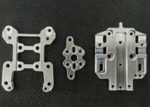
High-fidelity prototypes closely resemble the final product in terms of dimensions, appearance, and functionality. They are often created using CNC machining, injection molding, or high-resolution 3D printing. These prototypes simulate the real user experience and are suitable for engineering validation, customer demonstrations, and investor presentations.
Looks-Like Prototype
A Looks-Like prototype emphasizes the visual and aesthetic aspects of the product, including size, color, surface finish, and texture. While they typically lack full functionality, they are valuable for market research, packaging verification, and collecting user feedback on design appeal.
Works-Like Prototype
Works-Like prototypes focus on replicating the product’s functional characteristics. They are often built with near-production materials and processes to validate mechanical strength, usability, or structural performance. While they may not match the final product’s appearance, they ensure the design meets functional goals.
Engineering Prototype
An Engineering prototype is developed to validate manufacturability, assembly precision, and real-world performance. These prototypes often use production-grade materials and processes to conduct fatigue tests, environmental evaluations, and process optimizations. They help ensure the product can be manufactured reliably and consistently.
Validation/Manufacturing Prototype
These prototypes are almost identical to the final product and are used for compliance testing, regulatory certification, and pre-production validation. They verify that the product meets industry standards, safety regulations, and customer expectations, providing the final confirmation before mass production.
What Are the Main Processes Used in Rapid Prototyping
Rapid prototyping applies subtractive (CNC, laser/waterjet, sheet forming), additive (SLA, FDM, SLS, MJF, metal printing), and molding (injection, vacuum, silicone). These methods balance precision, speed, and cost, supporting stages from concept proof to pilot runs.
Subtractive Manufacturing
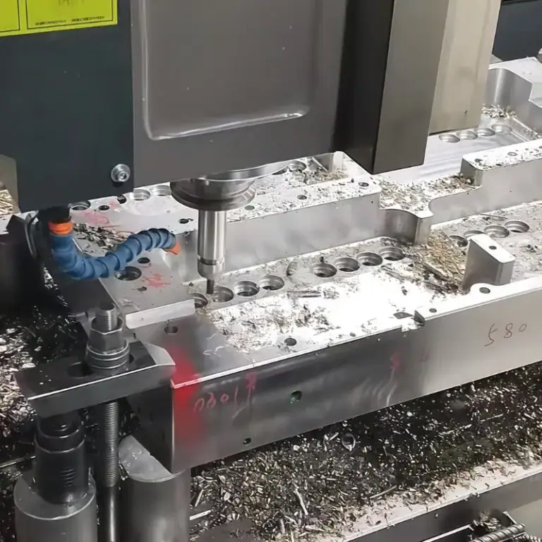
CNC Machining
CNC Milling
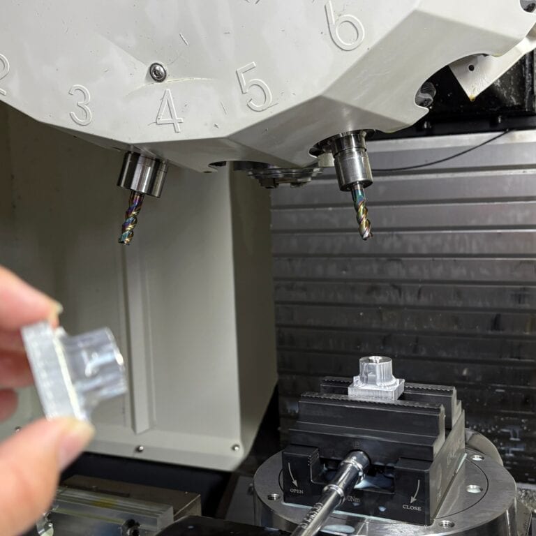
CNC milling shapes solid materials by removing material with multi-axis cutting tools. Typical tolerances reach ±0.01 mm, making it ideal for complex geometries and flat surface machining. It is widely used for metal and plastic prototypes, including appearance parts, cavities, slots, and precision surfaces. Key advantages include high repeatability, broad material compatibility, and the ability to produce engineering-grade functional parts.
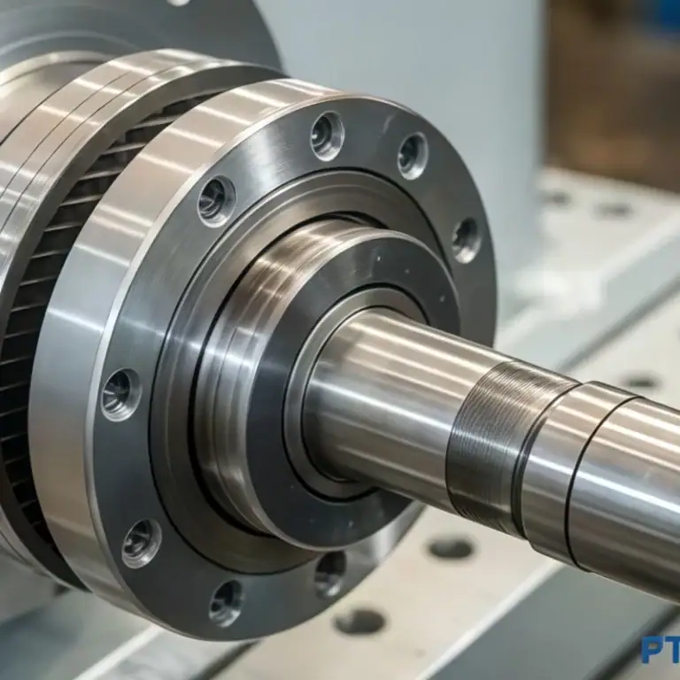
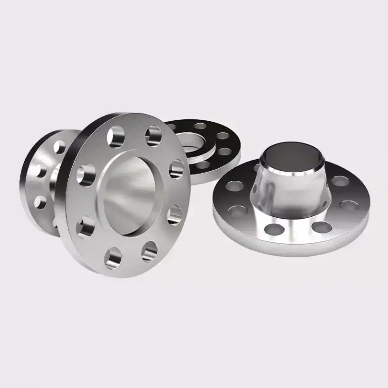
CNC Turning
CNC turning forms parts by cutting with stationary tools while the workpiece rotates at high speed. Typical tolerances reach ±0.01 mm, making it especially suited for cylindrical, conical, threaded, and shaft components. It is commonly applied to both metal and plastic prototypes for functional and engineering parts. Advantages include high efficiency, excellent dimensional consistency, and the ability to create complex symmetrical structures quickly.
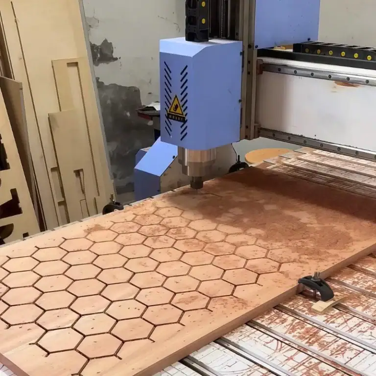
CNC Drilling
CNC drilling uses computer-controlled drill bits to produce highly accurate holes, with typical tolerances around ±0.02 mm. It is suitable for through holes, blind holes, and countersinks in both metal and plastic parts. Applications include assembly positioning, fastener installation, and functional testing samples. Advantages include precise hole accuracy, strong repeatability, and the ability to integrate seamlessly with milling and turning for multifunctional machining.
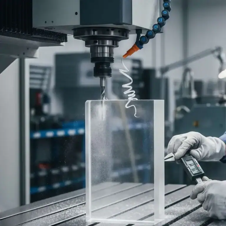
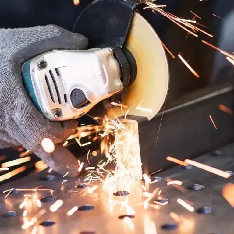
Laser/Waterjet Cutting
Laser cutting is ideal for thin sheets and complex contours, while waterjet cutting can process high-hardness materials such as ceramics and composites without heat-affected zones.
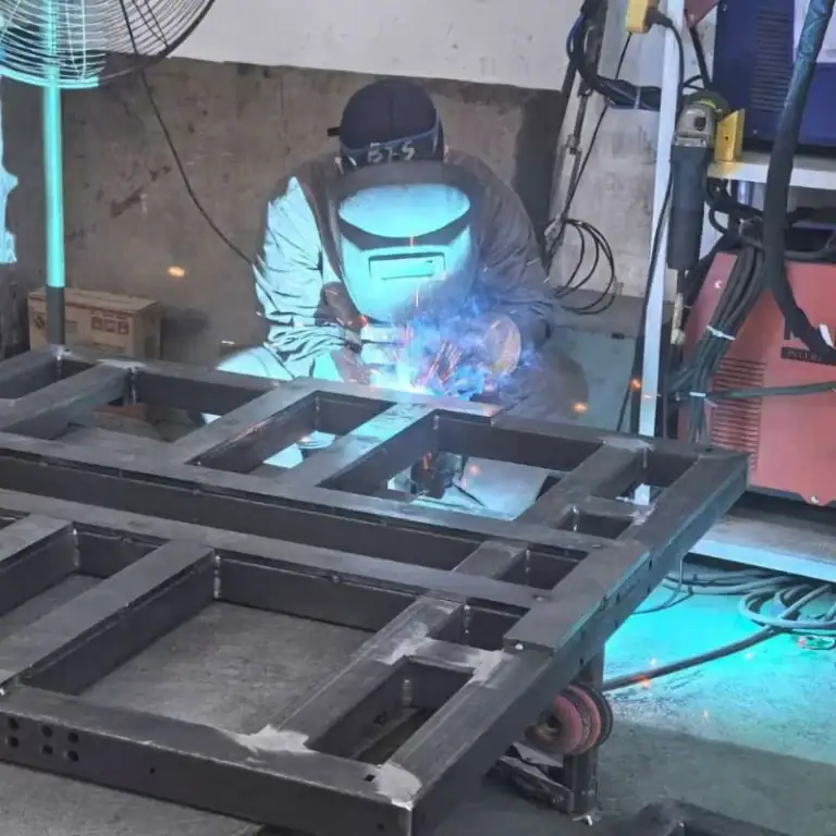
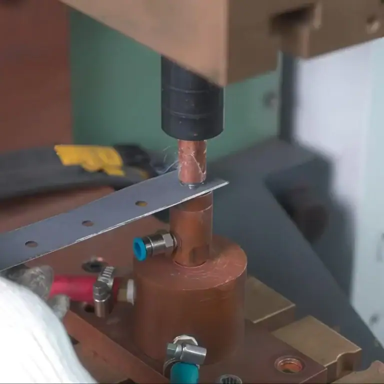
Sheet Metal Forming
Includes bending, stamping, and welding, often used for housings, brackets, and assembly prototypes.
Applications and Tolerances
Subtractive methods are best suited for engineering prototypes and functional testing where precision, strength, and surface finish are critical. Typical tolerances range from ±0.01 to ±0.05 mm.
Additive Manufacturing
Common Processes
SLA/DLP: High-resolution resin printing, layer thickness 25–100 μm, ideal for detailed appearance models.
FDM: Low-cost, widely accessible, suitable for concept models and low-fidelity functional prototypes.
SLS/MJF: Powder-based sintering for nylon and TPU, providing strong, durable, and heat-resistant parts.
PolyJet: Multi-material and full-color printing, widely used for appearance prototypes and medical devices.
LOM/Binder Jetting: Suitable for large-scale models or full-color parts.
Metal AM (SLM/DMLS, EBM): Used for titanium, stainless steel, and aluminum alloys, with layer thickness 20–50 μm. These processes are common in aerospace, automotive, and medical applications.
Key Metrics
Resolution: 25–200 μm (highest with resin-based printing, lowest with FDM).
Layer Thickness: 0.02–0.3 mm.
Build Speed: 10–100 cm³/h depending on process.
Size Range: Typically ≤500 mm³, with stricter limits for metal AM.
Tolerances: ±0.01–0.05 mm.
Material Compatibility: Plastics, resins, metals, ceramics, and composites.
Molding and Replication
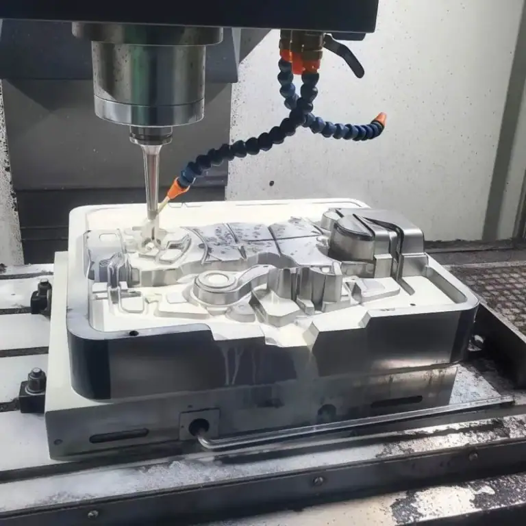
Injection Molding: Rapid tooling with aluminum molds or 3D-printed molds can deliver small-batch parts in under 24 hours, making it ideal for market validation and structural testing.
Vacuum Casting/PU Casting: Uses silicone molds to replicate 10–100 parts that simulate ABS, PC, or elastomers, with short lead times and lower cost.
Silicone Molds: Cost-effective for appearance validation and small-batch functional tests.
What Is The Common Materials for Rapid Prototyping
Common rapid prototyping materials include polymers, metals, and composites. Polymers enable low-cost concept and appearance models, metals support strength and functional testing, while composites and specialty options address transparency, heat resistance, and biocompatibility, covering the full cycle from proof of concept to engineering use.
| Category | Material Examples | Key Features | Typical Applications |
| Polymers | FDM Thermoplastics (ABS, PLA, PC) | Low cost, easy to process, moderate strength | Concept models, low-fidelity prototypes |
| SLA Photopolymer Resins (standard, heat-resistant, transparent) | High resolution, smooth finish, aesthetic parts | Appearance models, detailed designs | |
| SLS Nylon (PA11, PA12) | High strength, impact resistance, good durability | Functional prototypes, housings, gears | |
| Elastomers (TPU, TPE) | Flexible, rubber-like behavior | Soft grips, seals, wearable components | |
| Metals | Aluminum (6061, 7075) | Lightweight, machinable, good strength-to-weight | Engineering prototypes, aerospace, robotics |
| Stainless Steel (304, 316L) | Corrosion resistant, strong | Medical devices, structural components | |
| Tool Steel | High hardness, wear resistance | Molds, tooling, heavy-duty parts | |
| Titanium Alloy (Ti-6Al-4V) | High strength, lightweight, biocompatible | Aerospace, implants, high-performance parts | |
| Composites & Special | Carbon Fiber Composites | Lightweight, high stiffness | Structural parts, sports equipment |
| Transparent Plastics (PMMA, PC) | Optical clarity, toughness | Optical parts, aesthetic validation | |
| High-Temp Plastics (PEEK, ULTEM) | Heat resistant >200 °C, excellent strength | Aerospace, automotive, electronics | |
| Biocompatible Materials (medical resin, Ti, SS) | Safe for body contact, FDA-compliant options | Implants, surgical tools, medical devices |
What Software and Toolchains Are Needed for Rapid Prototyping
Rapid prototyping requires a full software and hardware chain, including CAD/CAE modeling, slicing and DFM tools, collaboration platforms, plus 3D printing, CNC machines, fixtures, and training systems to ensure efficient iteration, accurate validation, and fast delivery.
Software and Toolchains
CAD (Computer-Aided Design): Builds 3D models and product structures, serving as the core entry point of rapid prototyping.
CAE (Computer-Aided Engineering): Enables multiphysics simulations such as stress, fluid, and thermal analysis to ensure design feasibility.
Slicing Software: Converts 3D models into layered manufacturing paths for 3D printing and additive processes.
Simulation & Optimization: Predicts deformation, warping, and strength, minimizing trial-and-error costs.
DFM (Design for Manufacturability) Tools: Checks manufacturability and optimizes structures to improve production readiness.
Collaboration & Data Management: Facilitates cross-department sharing, version control, and change tracking to enhance efficiency.
Hardware & Supporting Tools
Printing Equipment: Includes SLA, SLS, FDM, and MJF machines for diverse additive prototypes.
CNC Machines: 3-axis and 5-axis setups for high-precision subtractive manufacturing of functional and engineering parts.
Fixtures & Jigs: Assist in assembly, alignment, and testing, ensuring accuracy and repeatability.
Sample Request & Tracking: Standardized workflow to monitor prototype lifecycle from design to delivery.
Demonstration & Training Tools: Showcase prototype functionality and train operators for consistent process execution.
How Is Post-Processing and Quality Inspection Performed in Rapid Prototyping
Post-processing includes support removal, cleaning, curing/sintering, and surface finishing, with CNC ensuring ±0.01 mm accuracy. Quality inspection involves dimensional checks, functional and reliability testing, plus compliance with ISO 13485, ISO 10993, AS9100, and FAA standards, ensuring prototypes meet medical and aerospace requirements.
Post-processing
After fabrication, rapid prototypes typically undergo multi-step post-processing:
Support Removal & Cleaning: Printed parts require support removal and ultrasonic cleaning; residual powders are cleared using airflow or vacuum.
Curing/Sintering: SLA/DLP resin parts require UV curing to improve strength by 20–40%; metal parts undergo sintering at 1200–1350 °C, achieving up to 99% density.
Surface Finishing: Sandblasting, polishing, plating, or coating reduce roughness (Ra from 10–20 μm down to 1–3 μm).
Precision Machining: Critical surfaces are CNC-finished to ±0.01 mm tolerance, enabling engineering-grade functional parts.
Quality Inspection
Dimensional Inspection: CMM or laser scanning ensures geometric accuracy of ±0.01–0.05 mm.
Functional & Reliability Testing: Mechanical (tensile, fatigue), thermal cycling (-40 °C to 200 °C), and chemical resistance tests validate performance.
Regulatory & Compliance: Medical devices follow ISO 13485 and biocompatibility (ISO 10993); aerospace requires AS9100 and FAA compliance to guarantee material and structural reliability.
How to Select the Right Rapid Prototyping Method
Selecting the right rapid prototyping method requires comparing process pros and cons, deciding when to in-house or outsource, and assessing in-house adoption based on iteration and delivery needs. Cost reduction can be achieved through material optimization, minimizing surface finishing, and leveraging digital manufacturing.
Process Comparison Matrix
CNC machining is ideal for high-precision functional parts; SLA/DLP suits fine appearance models but with limited strength; SLS/MJF delivers strong nylon parts quickly; vacuum casting is best for small-batch validation.
When to In-house vs Outsource
In-house is suitable for long-term, high-volume, or rapid-response needs; outsourcing fits one-off, small-batch, or multi-process projects, reducing fixed investment.
Criteria for Bringing SLS/Printing In-house
Recommended when design iterations are frequent, output is stable, material use is focused, and delivery time is critical.
Cost Reduction Strategies
Use cost-effective materials, minimize unnecessary surface finishing, optimize designs, and apply digital manufacturing tools to reduce costs and improve efficiency.
What Factors Should Be Considered for Rapid Prototyping Costs and Scaling
Rapid prototyping costs depend on process, material, and time. Early low-cost iterations improve ROI. Scaling requires injection molding and fixtures. Common mistakes include material mismatch, ignoring assembly, and excessive finishing.
Cost/Time Estimation and ROI
Process selection impacts cost
CNC machining generally costs more per part than 3D printing but offers ±0.01 mm precision, making it ideal for functional and engineering validation parts.
Material price differences are significant
SLA resin printing is cheaper but has limited strength, suitable for visual models or low-load prototypes. Engineering materials like nylon or aluminum are more expensive but meet higher performance requirements.
Machining time affects lead time
CNC machining of complex parts may take hours to days, while FDM/SLA printing can complete within 1–24 hours. Processing speed directly impacts the overall development cycle.
ROI depends on iteration strategy
Using low-cost prototypes in the early stage enables quick validation, reducing late-stage rework and tooling modification costs, thereby lowering overall R&D investment.
Transition from Prototype to Mass Production
Once the design is validated, scaling requires shifting to production processes. Aluminum molds (30–50% of steel mold cost) are ideal for low-volume injection molding. Jigs and fixtures ensure assembly consistency. Entry into mass production typically follows successful functional, assembly, and compliance testing.
Common Mistakes and Avoidance
Frequent mistakes include material mismatch (e.g., PLA replacing high-strength nylon), neglecting assembly tolerances, and over-polishing early prototypes. To avoid these, define validation goals, select appropriate material grades, keep tolerances within ±0.1 mm, and minimize surface finishing at early stages to save time and cost.
How to Start a Rapid Prototyping Project
Starting a rapid prototyping project requires CAD files, part quantities, tolerances, finishing, and deadlines. Vendors should be assessed on capabilities, certifications, experience, and cost clarity. Validation with 1–2 samples and feedback testing is recommended. Use CAD/CAE, slicing, and DFM tools with vendor resources for efficiency.
Request Documentation & Quotation Essentials
File Formats: Standard STEP, IGES, or STL to ensure complete 3D data.
Quantity: Specify single prototype or small batch (1–100 pcs).
Precision: Define tolerances (typically ±0.01–0.05 mm) to guide process selection.
Surface Finishing: Indicate if sandblasting, polishing, plating, or painting is required.
Lead Time: Prototypes often require 1–7 days delivery; specify clearly in the request.
Vendor Selection Checklist & Evaluation Criteria
Technical Capabilities: CNC, 3D printing, vacuum casting, and other processes.
Quality System: Certifications such as ISO9001, AS9100, or ISO13485.
Industry Experience: Proven track record in automotive, medical, or aerospace prototypes.
Delivery Performance: ≥95% on-time delivery as benchmark.
Cost Transparency: Ensure quotes include finishing and logistics to avoid hidden costs.
Obtain Samples/Demos
Sample Request: Order 1–2 parts to validate process and finish quality.
Demo Access: Some vendors offer online dashboards or machining videos for progress tracking.
Feedback & Testing: Use samples for assembly or functional validation to minimize redesign.
Starter Checklist & Resources
Checklist: CAD files, requirement specs, target quantity, delivery deadline.
Tools: Combine CAD/CAE, slicing, and DFM tools for higher design efficiency.
Learning Resources: Leverage vendor whitepapers, case studies, and online quoting tools.
In which industries is rapid prototyping used
Rapid prototyping is widely applied in consumer electronics, automotive, medical, aerospace, and industrial equipment. It supports concept validation, functional testing, and regulatory compliance, accelerating iterations, reducing R&D risks, and shortening time-to-market.
| Industry | Typical Use Cases | Application Stages |
| Consumer Electronics | Casings, buttons, connectors | Concept validation, assembly testing, functional verification |
| Automotive | Engine parts, interiors, lighting | Functional testing, durability trials, regulatory compliance |
| Medical | Anatomical models, implants, surgical guides | Concept design, functional simulation, compliance (ISO 13485) |
| Aerospace | Turbine blades, structures, lightweight brackets | Assembly validation, functional/lifecycle tests, certification (AS9100/FAA) |
| Industrial Equipment | Jigs, housings, wear-resistant parts | Concept proofing, functional trials, long-term reliability tests |
FAQs
What Is The Basic Principle Of Rapid Prototyping?
The core principle of rapid prototyping is turning CAD designs into physical models through additive or subtractive methods. I focus on speed and iteration: 3D printing builds layer by layer, while CNC machining achieves ±0.01 mm tolerance. This lets me validate geometry, function, and assembly early, minimizing redesign and shortening R&D cycles.
What Are The Steps Of Rapid Prototyping?
When I run a rapid prototyping project, I follow a structured flow to ensure reliability and efficiency. It begins with CAD modeling of design concepts, followed by data preparation such as STL slicing. Fabrication is then carried out using processes like CNC machining, SLA, SLS, or casting. Afterward, post-processing improves surface quality and dimensional accuracy. Finally, quality inspection at ±0.01–0.05 mm tolerance and functional or assembly testing validate the prototype’s performance.
What Software Is Used For Rapid Prototyping?
I typically use CAD software such as SolidWorks, CATIA, or Fusion 360 for modeling. For engineering analysis, CAE tools like ANSYS validate stress, thermal, and fluid performance. Slicing software (Cura, PreForm) converts 3D models for printing. CAM tools like Mastercam generate CNC codes. These integrated tools ensure accuracy, efficiency, and data continuity across the prototyping workflow.
What Is The Most Popular Prototyping Tool?
In my experience, 3D printing is the most widely used prototyping tool due to flexibility and cost. FDM is preferred for quick, low-cost drafts; SLA for fine features (layer thickness 25–100 µm); and SLS/MJF for nylon parts with high strength. Combined with CNC machining for tight tolerances, 3D printing covers over 70% of prototyping demand in modern industries.
How Much Does Rapid Prototyping Cost?
The cost depends on technology, materials, and part complexity. For example, an SLA prototype may cost $50–$200, FDM parts as low as $10, while CNC machining of metal components ranges from $100 to $1,000. On average, I estimate $100–$500 per prototype. By using low-cost iterations early, I reduce late redesign expenses and improve overall ROI.
Conclusion
Rapid prototyping is now vital in product development, combining CNC, 3D printing, and digital design for faster iterations, lower costs, and reliable results. From concept to compliance, it shortens time to market, helping industries like electronics, automotive, aerospace, and healthcare accelerate innovation and reduce risks.Do you have any ideas or needs regarding rapid prototyping? We look forward to hearing from you.