Milling is one of the most widely used processes in modern machining—but many beginners still wonder what milling is and how it fits into manufacturing. If you’re exploring what is milling in manufacturing, this guide walks you through how milling works, why it’s essential, and where it’s used. From precision components to complex industrial parts, you’ll learn exactly why milling remains a core technology across engineering industries.
What Is CNC Milling
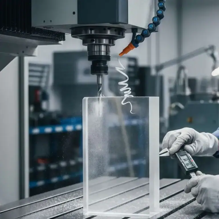
Milling is one of the most widely used subtractive manufacturing processes, where a rotating cutting tool removes material to form precise shapes, surfaces, and features. Whether producing prototypes or high-tolerance production parts, understanding how milling works is essential for choosing the right method and improving manufacturing efficiency.
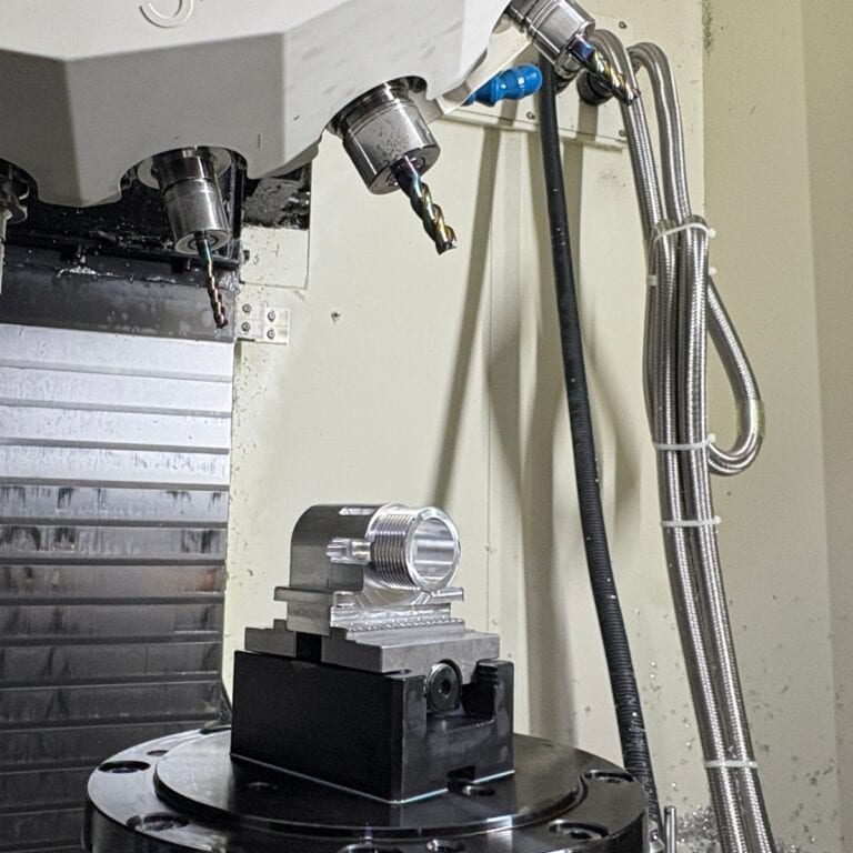
Milling operates by rotating a multi-edge cutter against a fixed or moving workpiece, generating material removal through controlled feed and cutting parameters. Modern CNC milling enhances this process with software-driven accuracy, enabling tolerances as tight as ±0.01 mm and repeatable quality in metal, plastic, and composite materials.
How Milling Works
Understanding how milling works is essential for choosing the right machining strategy. Milling uses a rotating, multi-edge tool to remove material with precision, allowing engineers to create complex shapes, surfaces, and features across virtually any industry.
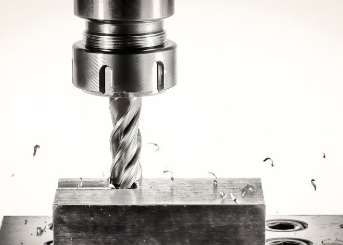
Milling relies on a rotary cutting tool—usually with multiple flutes—that removes material as it spins at speeds often exceeding 6,000–18,000 RPM. The tool moves along programmed paths (X, Y, Z) while the workpiece stays fixed or moves depending on machine configuration.
From my CNC shop experience, the cutting action occurs as the tool meets the workpiece at the rotating tangent, shearing off chips layer by layer. Tool engagement parameters such as axial depth (ap) and radial width (ae) define how aggressive each pass is.
Modern CNC milling uses:
- G-code paths for consistent accuracy
- High-speed machining to reduce heat buildup
- Carbide cutters for rigidity and burr-free edges
Types of Milling Process
Milling operations are the core of modern manufacturing, enabling precise shaping of metal, plastic, and composite parts. Understanding the major milling methods helps engineers choose the right process for accuracy, surface finish, and productivity.
Face Milling
Face milling uses a cutter with inserts on the tool face, making it ideal for creating flat surfaces and achieving Ra 0.8–3.2 µm finishes. Because most cutting happens at the tool’s periphery, it removes large areas quickly—common in housing surfaces, machine bases, and mold plates. In my CNC shop, we use 80–125 mm cutters to reduce cycle time for large aluminum plates.
End Milling
End milling uses a tool with cutting edges on both the end and sides, allowing slotting, pocketing, contouring, and 3D surfaces. It is essential for precision features like pockets, channels, and chamfers. Tools typically range from Ø1–20 mm and work well for tight-tolerance designs.
Peripheral (Side) Milling
Peripheral milling removes material along the cutter’s circumference. It excels at generating long, straight features such as shoulders, steps, and deep grooves. Compared with face milling, it delivers superior dimensional accuracy.
Slot Milling
This method cuts narrow channels with a full-width end mill. It is used for keyways, O-ring grooves, and mechanical guides. Carbide tools ensure stable cutting even in hardened steels (45–55 HRC).
Profile & Contour Milling
Used for 2D/3D shapes, including curved walls, sculpted profiles, and mold surfaces. High-speed machining (HSM) strategies greatly improve tool life and surface finish.
Thread & Gear Milling
These operations create threads and gears with exceptional precision. Thread milling avoids the stress concentration of tapping, while gear milling is common for industrial robotics and transmission systems.
Chamfer & Face Finishing
Used at the end of machining to remove burrs, improve assembly fit, and ensure safety. Typical angles: 45°, 30°, or custom.
Types of Milling Machines
Understanding the different types of milling machines is essential because each machine offers unique capabilities, cutting directions, and productivity advantages. Choosing the right machine directly affects precision, cycle time, and cost—especially in modern CNC-driven manufacturing.
Milling machines differ mainly by spindle orientation, rigidity, and the scale of material removal they can achieve. Here are the most common industrial types:
Vertical Milling Machines (VMC)
These use a vertically oriented spindle, ideal for face milling, pocketing, contouring, and precise 3D shaping. VMCs dominate prototype machining and small-to-medium production because they offer excellent accuracy and easy setup.
In my CNC projects, VMCs handle 80% of aluminum and plastic parts thanks to their versatility.
Horizontal Milling Machines (HMC)
HMCs feature a horizontal spindle, enabling stronger chip evacuation and deeper cuts. They are preferred for steel, cast iron, and large-volume material removal.
HMC users often report 20–40% higher productivity in mass-production environments.
Universal Milling Machines
A hybrid system combining vertical and horizontal capabilities. These machines are popular in tool rooms because operators can switch cutting directions for complex fixturing and multi-angle machining.
Bed Mills
These heavy-duty machines have the table fixed while the spindle moves vertically. Their rigidity makes them suitable for machining large steel components or thick plates that require deep and stable cutting passes.
CNC Milling Machines
Controlled by digital programs, CNC mills allow automated machining with repeatability often within ±0.01 mm. They support multi-axis configurations (3-axis to 5-axis), enabling highly complex geometries.
In our shop, 5-axis CNC reduces machining time for aerospace brackets by up to 50%.
Key Milling Parameters
Understanding key milling parameters is essential for achieving accuracy, tool life, and machining efficiency. Whether you’re optimizing feeds, speeds, or cutting depths, mastering these values ensures better surface quality, longer tool performance, and more predictable results.
Key milling parameters determine how effectively material is removed and how stable the machining process remains:
- Feed Rate (mm/min): Controls how fast the tool moves across the workpiece. Higher feed = faster machining but more tool load.
- Spindle Speed (RPM): Sets cutter rotation speed. Higher RPM improves finish but increases heat.
- Depth of Cut (DOC):
– Axial DOC (AP): Determines how deep the cutter engages vertically.
– Radial DOC (AE): Sets the cutter engagement width and affects tool deflection.
- Cutting Speed (SFM or m/min): Influences chip formation and heat generation.
- Tool Diameter: Larger diameter increases rigidity but limits tight geometries.
- Tool Overhang: Longer overhang increases vibration; keeping it minimal improves accuracy.
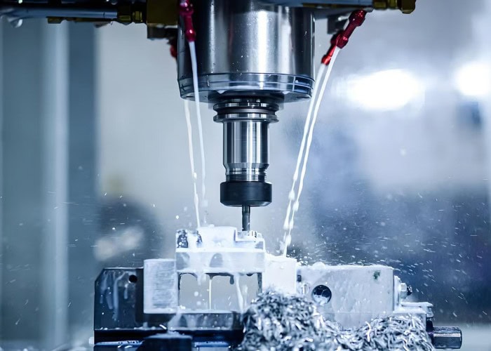
- Coolant Flow: Essential for chip evacuation and heat control.
- Tool Coating: TiN, TiAlN, or DLC coatings help reduce wear, especially in metals.
- Stepover: Determines scallop height in finishing passes; smaller stepover = smoother surfaces.
- Ramp Angle: Defines entry angle for plunging to reduce tool stress.
In my machining projects, properly balancing feed rate, spindle speed, and radial DOC often yields the biggest improvements in both accuracy and tool life, especially for harder materials like stainless steel.
Suitable Materials & Limitations
Milling is highly versatile, capable of shaping metals, plastics, composites, and even woods with precision. However, each material behaves differently under cutting forces and heat. Understanding which materials machine well—and which require caution—helps engineers choose the most efficient and cost-effective approach.
Metals
Metals remain the most frequently milled materials thanks to their strength and predictability under cutting forces.
Common machinable metals include:
- Aluminum (excellent machinability, low tool wear)
- Stainless steel & alloy steels (require rigid setups, generate heat)
- Copper & brass (easy to machine, ideal for precision components)
- Nickel & chrome alloys (harder, require coated carbide tools)
In my shop, aluminum 6061 and 7075 consistently offer the best balance between cutting speed and accuracy.
Plastics
Plastics machine well but require strict temperature control to avoid melting or deformation.
Common milled plastics: ABS, POM, Nylon, PC, PEEK.
For example, PEEK delivers excellent dimensional stability but demands sharp tools and cooling.
Composites
Composites provide high strength-to-weight ratios but tend to cause tool wear due to abrasive fibers.
Suitable composites include FRP, carbon fiber, metal-matrix composites, and ceramic-matrix composites.
Woods
Most hardwoods and softwoods can be milled easily, making CNC milling popular in furniture and mold pattern making.
Ceramics
Ceramics are brittle and prone to chipping. Milling is typically performed in the pre-sintered “green” state to avoid fracturing.
Material Limitations
Some materials pose additional risks:
- Brittle materials(glass, ceramics): prone to cracking and edge chipping
- High-hardness alloys(Inconel, hardened steels): increase tool wear, require low feed rates
- Reactive metals(magnesium, titanium): generate heat and may ignite if not cooled properly
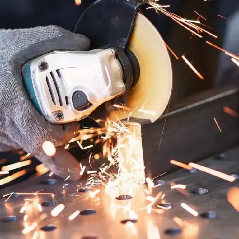
Advantages of Milling
Advantages of milling extend far beyond basic material removal. If you’re choosing a manufacturing method, understanding why milling delivers superior precision, versatility, and production efficiency will help you determine whether it’s the best fit for your parts.
Milling offers:
- High accuracy for complex geometries
- Compatibility with metals, plastics, composites, wood
- Fast production with strong repeatability
- Excellent surface quality that often eliminates secondary finishing
- CNC automation for reduced labor and increased consistency
- Cost-effective batch production
Common Problems & Troubleshooting
| Common Milling Problem | Description | Typical Causes | Solutions / Troubleshooting |
| Chatter (Vibration) | Excessive vibration that leaves marks on the part and damages tools. | Loose tool holding, aggressive cutting parameters, milling corners, long overhang. | Tighten tool setup, reduce spindle speed, increase feed, shorten tool overhang, use more rigid fixturing. |
| Tool Wear | Gradual degradation of the cutting edge leading to poor finish and dimensional errors. | Incorrect speeds/feeds, hard materials, insufficient coolant, improper tool coating. | Optimize cutting parameters, apply proper coolant flow, choose coated carbide tools, schedule tool changes. |
| Workpiece Deformation | Part warping or bending due to heat or cutting forces. | Thin walls, excessive heat buildup, improper clamping, aggressive depth of cut. | Reduce depth of cut, improve cooling, use optimized fixturing, machine symmetrically to balance stresses. |
| Poor Chip Evacuation | Chips re-cut by the tool, causing scratches, tool wear, or tool breakage. | Insufficient coolant flow, wrong tool flute design, deep pockets without chip clearance. | Use high-pressure coolant, choose tools with proper flute geometry, program chip-breaking toolpaths. |
| Tool Collision | Unintended contact between tool and part, causing tool breakage or scrapped parts. | Incorrect toolpath programming, inaccurate tool length measurement, poor setup. | Verify CAM simulation, measure tool length accurately, use machine limits and safe retract heights. |
Applications Across Industries
Milling is used far beyond machine shops. Thanks to its precision, material flexibility, and ability to form complex geometries, milling has become essential across industries like automotive, aerospace, electronics, and medical manufacturing. Here’s how each sector benefits.
Automotive Industry
Precision milling produces engine blocks, transmission housings, brake components, and lightweight aluminum structures. CNC milling ensures tolerances within ±0.01 mm, critical for high-performance engines and EV drivetrain systems.
Aerospace Industry
Aircraft components must be strong and lightweight. Milling is used for structural frames, landing gear, turbine parts, and avionics housings. 5-axis milling allows machining of complex aerodynamic surfaces from aluminum, titanium, and Inconel.
Electronics & Semiconductor
Heat sinks, precision housings, PCB molds, and connector components rely on milling for micro-scale accuracy. Milling achieves tight surface roughness values (Ra < 0.8 µm), which is essential for thermal management parts.
Medical & Dental
Milling produces implants, bone plates, surgical tools, and prosthetic components using stainless steel, titanium, and PEEK. The repeatability of CNC machining ensures consistent quality for devices that require strict biocompatibility.
Mold Making
From injection molds to die-casting and rubber molds, milling enables precise cavity and core shapes. High-speed milling achieves polished surfaces and fine textures directly on the mold.
Woodworking & Plastics Manufacturing
CNC routers mill hardwood, MDF, ABS, polycarbonate, and POM for furniture, prototypes, and custom components. Temperature-controlled milling prevents plastic deformation.
Choosing the Right Milling Method
Choosing the right milling method starts with understanding your material, part geometry, and required surface quality. By matching the process to your design and production goals, you ensure higher accuracy, longer tool life, and more consistent machining results.
Selecting the correct milling method depends on several technical factors:
Material Characteristics
Different materials respond differently to heat, cutting forces, and tool interaction.
- Hard metals (e.g., stainless steel, titanium): require rigid setups, carbide tools, lower feed rates.
- Plastics: need lower cutting heat to prevent melting; sharp tools and high chip evacuation are essential.
- Composites: abrasive; require coated tools and controlled entry angles to prevent delamination.
Material Removal Requirements
Large stock removal favors:
- Large-diameter end mills, multi-flute tools, high feed roughing.
Finishing thin walls or precision details requires:
- Small-diameter tools, lower cutting forces, fine stepovers.
Geometric Complexity
- Simple surfaces: face milling, side milling.
- Complex contours: ball-nose end mills, 5-axis simultaneous milling.
In my machining projects, switching from flat to sculpted surfaces usually reduces spindle speed and increases step-over control to maintain accuracy.
Machine Capability & Cutting Parameters
Spindle RPM, feed rate, tool rigidity, coolant strategy, and machine stability directly determine the achievable quality.
High-speed machines allow small tools to cut efficiently, while older machines need conservative cutting data.
Tool Selection for Each Operation
Tool geometry must match the operation:
- Slotting: 2–3 flute end mills.
- Finishing: 4–6 flute tools with polished edges.
- Deep pockets: long-reach carbide with vibration control.
Proper coatings (TiAlN, DLC, etc.) extend tool life, especially for stainless steel and composites.
FAQs
What Is The Golden Rule Of Milling?
The golden rule of milling is to “climb mill whenever possible.” In my experience, climb milling provides smoother cutting, lower tool wear, and better surface finish. It reduces cutting forces by up to 30% and improves tool life significantly, especially in CNC high-speed machining.
What’s The Difference Between CNC And Milling?
CNC is the automated control system, while milling is the machining process itself. Milling removes material using rotating tools; CNC controls tool paths with precision of ±0.01 mm. In short, CNC is the technology, milling is the operation it performs.
Is The Mill A CNC Machine?
A mill becomes a CNC machine when computer numerical control is added. Traditional mills use manual handwheels, but CNC mills use programmed commands for movements with repeatability of ±0.005–0.02 mm. So, not all mills are CNC, but all CNC mills are milling machines.
What Is The Difference Between CNC Milling And Manual Milling?
CNC milling uses programmed toolpaths for high accuracy and automation, achieving tolerances around ±0.01 mm. Manual milling relies on operator skill, has slower speed, and typical accuracy of ±0.05–0.1 mm. CNC is ideal for complex geometries; manual suits simple or one-off tasks.
What Is AE And AP In Milling?
AE and AP define cutting engagement. AE (Radial Depth Of Cut) controls side engagement and affects tool load; AP (Axial Depth Of Cut) defines vertical cutting depth. For example, AE = 20% tool diameter and AP = 1×D are common high-efficiency milling settings.
Conclusion
Milling is a core subtractive manufacturing process that uses rotating cutters to shape metal, plastic, and composite parts with high precision. By selecting the right machine, operation, and cutting parameters, engineers can achieve tight tolerances, fast production, and reliable quality across industries like automotive, aerospace, electronics, and medical manufacturing.