A micrometer is a precision measuring tool designed to measure very small dimensions with high accuracy—commonly to 0.01mm, and for higher-end models down to 0.001mm. If you’ve ever asked, what is a micrometer and why it matters in machining, the answer lies in its ability to deliver controlled, repeatable measurements where tight tolerances are critical. In CNC machining, I reach for a micrometer when a part’s fit, function, or assembly performance depends on dimensional consistency.
In this guide, how it’s used in real CNC shops, the types engineers rely on, and how measurement accuracy is defined, controlled, and protected on the shop floor.
What Is Micrometer?
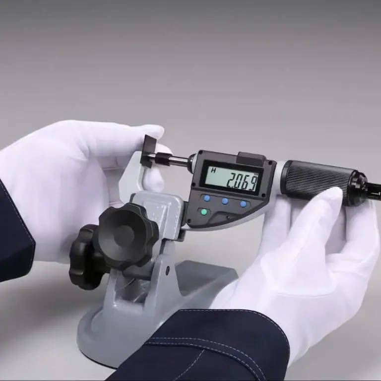
A micrometer is a high-precision measuring instrument used to verify small linear dimensions with excellent accuracy and repeatability. It is designed to measure parts using controlled contact pressure, ensuring stable and consistent measurement results. Micrometers are commonly available in both mechanical (analog) and digital versions and are widely used in precision inspection.
In CNC machining manufacturing, micrometers play a critical role in verifying part dimensions during production and quality control. They are typically used to measure:
-
Outside diameters of shafts, pins, bearing seats, and cylindrical bosses
-
Material thickness such as plates, ribs, steps, or thin walls
-
Depth or internal dimensions when using depth micrometers or inside micrometers
Compared with calipers, micrometers provide significantly higher resolution and measurement consistency. When dimensional tolerances become tighter than about ±0.02mm, calipers often cannot deliver reliable repeatability for quality inspection.
For example, when machining a bearing journal with a tolerance of ±0.005mm, dimensional verification must be extremely precise and stable. While a caliper may display a measurement value, it cannot reliably confirm micron-level accuracy. In such situations, the micrometer becomes an essential inspection tool in CNC machining manufacturing.
Micrometer vs Micron
The terms micrometer and micron are often confused in engineering contexts, but they refer to different things.
A micrometer can mean either:
-
A precision measuring instrument used in machining and inspection
-
A unit of length (also called a micron), written as μm
In measurement units, 1 μm equals 0.001 mm.
When an engineering drawing specifies a tolerance such as ±5 μm, it refers to an allowable dimensional variation of ±0.005 mm. The value describes the tolerance unit, while the micrometer tool is commonly used to verify that dimension during inspection.
What Is an Inside Micrometer and the Micrometer Unit?
The terms inside micrometer and micrometer unit (μm) are often confused in engineering measurement because they refer to different things. One is a precision measuring instrument used in machining inspection, while the other is a unit used to describe extremely small dimensions.
An inside micrometer is a precision measuring tool used to measure internal dimensions such as hole diameters, bores, and bearing housings. It is commonly used in CNC machining and inspection when accurate internal measurements are required.
The micrometer unit, written as μm, equals one-millionth of a meter or 0.001 millimeters. It is widely used in engineering drawings to define very small tolerances. For example, ±5 μm equals ±0.005 mm.
In simple terms, an inside micrometer is a measuring tool, while μm is a measurement unit.
What Is Micrometer Used For?
A micrometer is used to measure very small dimensions with high precision. It is commonly used in machining and inspection to verify that parts meet tolerances in engineering drawings. Because micrometers provide stable contact pressure and fine resolution, they are essential for inspecting critical dimensions in CNC machining.
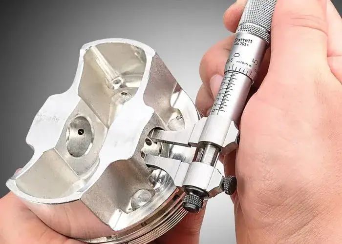
1.Measuring External Diameters
One of the most common uses of a micrometer is measuring the outside diameter of cylindrical parts such as shafts, pins, bearing journals, and precision bosses. In CNC machining, machinists often use an outside micrometer to verify that the diameter of a shaft is within the required tolerance before assembly.
2.Measuring Material Thickness
Micrometers are frequently used to measure the thickness of materials such as metal sheets, plastic components, plates, ribs, or thin walls. Because the measuring faces apply controlled contact pressure, the tool can provide stable and repeatable measurements even for thin or delicate parts.
3.Inspecting Internal Dimensions
When equipped with the correct type, micrometers can also measure internal dimensions. Inside micrometers are commonly used to measure the diameter of bores, holes, and bearing housings. This allows engineers to verify that internal features meet design specifications.
4.Measuring Depth Features
Depth micrometers are designed to measure the depth of slots, pockets, counterbores, or blind holes in machined parts. These measurements are important for verifying machining operations such as milling or drilling.
5.Verifying Tight Tolerances
Micrometers are especially useful when parts require tight dimensional control. Many micrometers provide measurement resolution of 0.01mm or even 0.001mm, making them suitable for precision inspection tasks in CNC machining, aerospace manufacturing, automotive components, and other high-precision industries.
By providing accurate and repeatable measurements, micrometers help engineers and machinists ensure that components meet design requirements and function correctly during assembly.
How Does a Micrometer Work?
Understanding how a micrometer works is essential in precision machining and quality control. Its accuracy comes from a precisely engineered screw mechanism that converts rotation into controlled linear displacement. Even digital micrometers rely on this same mechanical foundation. When engineers understand this principle, they can trust the readings and recognize potential errors such as wear, backlash, or inconsistent measuring force.
A micrometer converts rotational motion into precise linear movement using a finely machined screw. In a standard metric micrometer:
- Screw pitch: 0.5mm per full revolution
- Thimble divisions: 50
- Resolution: 0.01mm per division
Each thimble mark corresponds to a defined spindle movement. This mechanical relationship ensures consistent measurement and high repeatability when proper technique is applied.
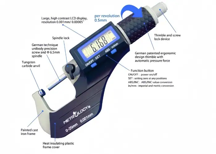
Main Parts of a Micrometer
A micrometer is composed of several precision components that work together to provide highly accurate dimensional measurements. Knowing each component helps you control force, alignment, and repeatability during inspection such as excessive force, misalignment, or incorrect scale interpretation.
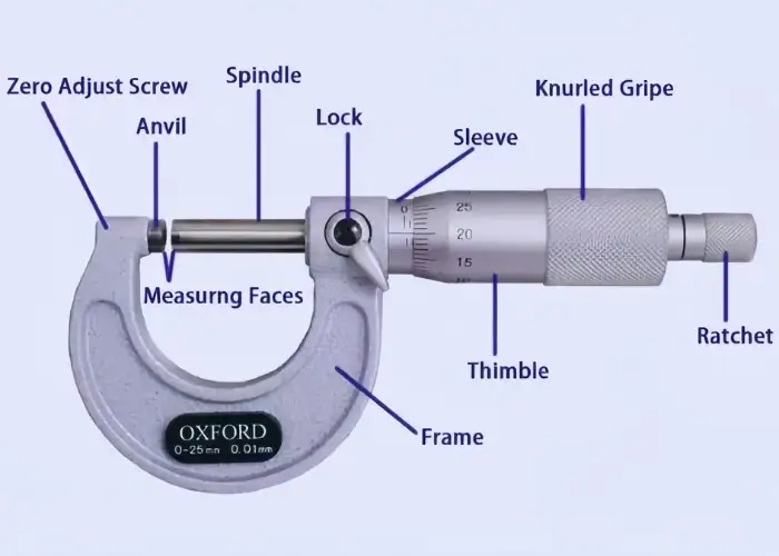
1.Frame
The frame is the rigid C-shaped body that holds the measuring system together. It maintains the alignment between the anvil and spindle and provides the structural stability required for accurate measurement.
High-quality frames are typically made from hardened steel or alloy materials to minimize deformation. Greater rigidity reduces deflection caused by measuring pressure, improving measurement stability.
2.Anvil
The anvil is the fixed measuring surface where the workpiece contacts one side of the tool. It serves as the primary reference point for every measurement.
Because the anvil directly touches the part surface, contamination such as burrs, dust, oil film, or plating residue can introduce measurement error. Keeping the anvil clean and undamaged is essential for reliable results.
3.Spindle
The spindle is the movable measuring face that advances toward the anvil as the thimble rotates. It provides the adjustable contact surface used to clamp the workpiece during measurement.
Spindles are usually hardened and precision-ground. Over time, wear or thread damage inside the spindle mechanism may cause systematic deviation, which is why regular calibration is recommended in precision machining environments.
4.Sleeve / Barrel
The sleeve, also known as the barrel, contains the primary measurement scale. It provides the reference markings used to read the main dimension value.
These markings represent larger measurement increments, while the thimble scale provides finer subdivisions for precise readings.
5.Thimble
The thimble is the rotating component used to move the spindle forward or backward. As it turns, the thimble scale displays fractional measurement increments.
Smooth rotation of the thimble allows precise positioning of the spindle and enables users to measure dimensions with high resolution.
6.Ratchet or Friction Thimble
The ratchet stop controls the measuring force applied to the part. Once the correct contact pressure is reached, the ratchet slips to prevent additional tightening.
This mechanism ensures consistent measuring force, which is critical when measuring thin walls, soft materials, or polished surfaces where excessive pressure could distort the reading.
7.Lock
The spindle lock allows the user to hold the measurement position after the spindle contacts the part. This feature is helpful when measurements need to be recorded or when the micrometer must be removed from the part before reading the scale.
8.Practical Measurement Tip
In real inspection work, measuring force is often underestimated. When measuring thin sections, soft plastics, or highly polished parts, inconsistent pressure alone can create noticeable measurement variation.
Using the ratchet mechanism consistently helps maintain stable and repeatable measurement results.
8 Types Of Micrometers
Micrometers used in precision inspection are commonly divided into eight main types, each designed for specific measurement tasks in CNC machining. These micrometers allow engineers to accurately measure external diameters, internal bores, depths, threads, and complex surfaces. Choosing the correct type improves measurement accuracy, repeatability, and inspection efficiency.
The table below summarizes the 8 types of micrometers and their typical CNC applications:
|
Micrometer Type
|
Typical CNC Application
|
|
1.Outside Micrometer
|
Shafts, pins, external diameters
|
|
2.Digital Micrometer
|
Batch inspection, SPC data logging
|
|
3.Inside Micrometer
|
Bores, bearing housings
|
|
4.Depth Micrometer
|
Pockets, counterbores, step depths
|
|
5.Thread Micrometer
|
Thread pitch diameter
|
|
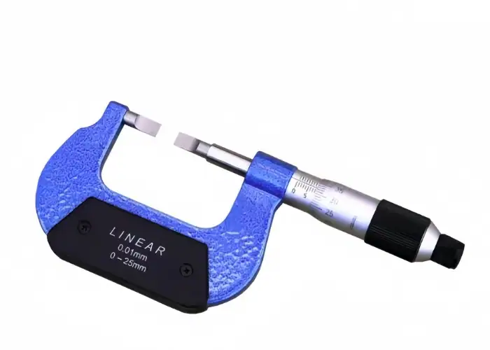
6.Blade Micrometer
|
Narrow grooves and slots
|
|
7.Ball Micrometer
|
Curved or spherical surfaces
|
|
8.Bench Micrometer
|
High-stability inspection setups
|
How to Choose the Right Micrometer Measuring Range for Accurate Inspection?
Choosing the correct micrometer measuring range is one of the most important steps in achieving accurate dimensional inspection. In CNC machining environments, measurement accuracy depends not only on the tool’s resolution but also on selecting a micrometer with an appropriate measuring range for the feature being inspected. Using the correct range improves tool stiffness, alignment stability, and measuring force control, which helps reduce measurement errors and ensures reliable inspection results.
Select the Smallest Suitable Measuring Range
Outside micrometers are commonly manufactured in fixed 25 mm measuring ranges, such as 0–25 mm, 25–50 mm, 50–75 mm, and so on. When measuring a feature, engineers and machinists should always select the smallest range that fully covers the target dimension.
A smaller measuring range provides several advantages. Shorter-frame micrometers are generally stiffer and easier to align, which improves measurement stability. They also allow better control of the measuring force applied through the spindle, helping prevent inconsistent readings.
Why Measuring Range Affects Accuracy?
Longer-range micrometers tend to be less rigid and more sensitive to alignment errors. Even if the instrument has high resolution, excessive frame length can slightly affect stability during measurement. For this reason, choosing a micrometer with the correct measuring range is a simple but highly effective way to improve inspection reliability.
In practical CNC production environments, proper range selection helps machinists achieve more consistent measurements, reduce repeatability errors, and avoid unnecessary adjustments during quality inspection.
5 Factors That Affect Measurement Accuracy in CNC Inspection
Measurement accuracy in CNC inspection is influenced by five key factors: temperature, measuring force, alignment, surface condition, and operator technique. Even when using high-precision instruments such as micrometers, these variables can introduce measurement errors if they are not properly controlled. Understanding and managing these factors helps improve repeatability, reduce dimensional variation, and ensure reliable inspection results.
1.Temperature
Metal expands and contracts with temperature. Steel expands approximately 11μm per meter per °C, which means even small temperature differences can influence dimensional readings in precision inspection.
Freshly machined parts often retain heat from cutting operations. Measuring these parts immediately can produce slightly oversized readings. As the part cools, the dimension may decrease, creating inconsistent measurement results.
For reliable inspection, both the measuring tool and the workpiece should stabilize near room temperature before final measurement. In many inspection environments, 20°C is used as the standard reference temperature.
2.Measuring Force
Measuring force directly influences dimensional readings, especially when inspecting thin walls or softer materials. Excessive spindle pressure can compress the surface slightly and produce a smaller measurement value.
Micrometers include a ratchet stop or friction thimble to ensure consistent contact pressure. Using the ratchet mechanism instead of manually tightening the thimble helps maintain repeatable measuring force and prevents over-tightening.
This control becomes especially important when measuring delicate features such as thin sections, plastic components, or polished surfaces.
3.Alignment
Accurate readings require proper alignment between the micrometer measuring faces and the workpiece surface. If the spindle and anvil contact the part at an angle, the measurement will not represent the true dimension.
Misalignment can occur when the tool is tilted or when the part is not seated correctly. A common technique is to gently rock the micrometer across the measurement point to locate the position where the reading is highest. This position typically represents the true dimension.
4.Surface Condition
Surface condition has a direct impact on measurement accuracy. Burrs, rough machining marks, coolant residue, or plating layers can prevent full contact between the micrometer faces and the part surface.
Even a small burr can change the reading by several microns. Before measuring critical features, the part should be cleaned, wiped free of oil, and lightly deburred. Ensuring smooth contact between the measuring surfaces helps improve measurement reliability.
5.Operator Technique
Operator technique plays a major role in measurement repeatability. Even with the same instrument, inconsistent handling can produce different readings.
Good measurement practice includes aligning the micrometer carefully, using the ratchet mechanism consistently, and repeating the measurement several times to confirm the result. Skilled machinists often develop a consistent measurement routine that minimizes human-induced variation.
Common Sources of Measurement Error
Accurate micrometer readings can be affected by several common inspection errors. In CNC environments, factors such as temperature differences, excessive measuring force, misalignment, surface contamination, or inconsistent operator technique may introduce measurement bias.
The table below summarizes typical error sources, their causes, and the type of reading deviation they can produce during inspection:
| Factor | Typical Cause | Result |
|---|---|---|
| 1.Temperature | Measuring hot parts | Oversized readings |
| 2.Measuring force | Over-tightening spindle | Undersized readings |
| 3.Alignment | Tool not perpendicular | Inconsistent values |
| 4.Surface condition | Burrs or oil film | False measurement |
| 5.Operator technique | Inconsistent contact pressure | Poor repeatability |
This quick reference helps inspectors identify potential sources of measurement error before relying on a reading.
How To Read A Micrometer?
Step-by-Step Micrometer Reading Method
A micrometer combines values from two scales to produce a precise measurement. The sleeve displays the base dimension, while the thimble provides the fine increment. Following a clear sequence helps prevent common reading mistakes.
A typical reading process includes three steps:
1. Read the main dimension on the sleeve scale.
Identify the last visible whole-millimeter mark to the left of the reference line. This represents the base value of the measurement.
2. Add the 0.5 mm mark if it has passed the reference line.
If the half-millimeter mark is visible beyond the reference line, include an additional 0.5 mm in the reading.
3. Add the thimble reading.
The thimble scale provides the fine measurement increment, typically 0.01 mm per division in a metric micrometer. Align the thimble mark with the reference line to determine the decimal value.
Repeating the measurement once or twice helps confirm the reading and reduces the risk of inspection errors.
Micrometer Reading Example
For example, if the sleeve scale shows 12 mm, the 0.5 mm mark is visible, and the thimble aligns at 28 divisions, the final measurement is calculated as:
12 mm + 0.5 mm + 0.28 mm = 12.78 mm
Repeating the measurement helps confirm repeatability and ensures the reading is reliable for precision CNC inspection.
Common Reading Mistakes
Most micrometer errors in CNC inspection do not come from the instrument itself—they come from technique. Even a properly calibrated micrometer can produce incorrect results if the part is not seated correctly, the measuring force is inconsistent, or the reading sequence is rushed. Developing a consistent measurement routine is critical for reliable tolerance control.
When to Choose a Micrometer Over Other Tools?
A micrometer should be selected when high measurement accuracy and reliable inspection results are required. Compared with general measuring tools such as calipers, micrometers provide controlled measuring force, stable contact geometry, and higher repeatability, which makes them more suitable for precision dimensional verification.
Micrometers are commonly used in the following situations:
-
Tight tolerance inspection
When dimensional variation must be controlled within a few microns, micrometers provide the accuracy needed to verify precision CNC components. -
Measuring small diameters or thickness
They are ideal for inspecting shaft diameters, thin walls, precision plates, and other small linear dimensions that require stable measurement. -
Verifying press-fit and bearing seats
Many mechanical assemblies depend on precise fits. Micrometers allow engineers to confirm that shafts and bores meet the required interference or clearance specifications. -
Final inspection and quality control
Micrometers are often used during first-article inspection and final dimensional verification to ensure parts meet engineering drawings and tolerance limits. -
Checking wear or dimensional variation
In maintenance or production environments, micrometers help detect small dimensional changes caused by wear, deformation, or machining drift.
Because of their high accuracy, controlled measuring force, and excellent repeatability, micrometers are essential whenever precise dimensional verification is required in CNC machining and engineering inspection.
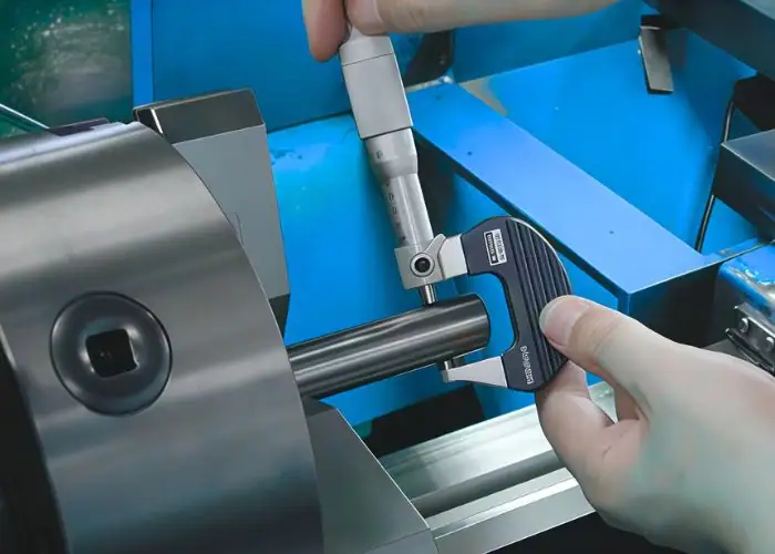
Applications of a Micrometer
A micrometer is widely used in precision measurement where high accuracy and repeatability are required. In modern CNC machining manufacturing, micrometers play an essential role in verifying critical dimensions during production, inspection, and quality control. Their high resolution allows engineers and machinists to confirm whether machined parts meet tight tolerance requirements.
Common applications of micrometers include:
-
Measuring the outside diameters of shafts, pins, bearing seats, and cylindrical features
-
Checking material thickness, such as metal plates, ribs, thin walls, and stepped surfaces
-
Inspecting internal diameters or depths when using inside micrometers or depth micrometers
-
Verifying precision tolerances during machining and final quality inspection
In CNC machining manufacturing, dimensional accuracy directly affects part performance and assembly quality. When tolerances are very tight, such as ±0.01mm or smaller, micrometers provide more stable and reliable measurements than standard calipers.
For example, when machining precision components like bearing journals or sealing surfaces, engineers rely on micrometers to ensure that the final dimensions remain within the specified tolerance range. This helps maintain product quality, reduce machining errors, and ensure consistent performance in mechanical assemblies.
FAQs
How Accurate Is A Micrometer Compared To A Caliper?
A micrometer is generally 5–10 times more accurate than a standard caliper. Most calipers have a resolution of about 0.02 mm and a typical measurement accuracy of ±0.02–0.03 mm, which is sufficient for general dimensional inspection and setup verification.
Micrometers typically achieve ±0.002–0.01 mm accuracy, depending on tool quality and measuring range. This higher precision makes them better suited for checking tight CNC tolerances, such as bearing journals, shaft diameters, and press-fit components.
Why Are Micrometers More Accurate?
Micrometers achieve higher accuracy because of their precision screw mechanism and rigid structural design. The rotating thimble drives a finely threaded spindle that converts rotation into extremely small linear movement. This allows the tool to measure very small dimensional differences with predictable motion.
Most micrometers also include a ratchet stop or friction thimble, which ensures consistent measuring force. This prevents excessive pressure on the part and improves measurement repeatability during inspection.
What Is A Digital Micrometer?
A digital micrometer is a precision measuring tool that displays measurement values on an electronic digital screen instead of a mechanical scale. Internally, the measuring principle is similar to a mechanical micrometer, but the digital display removes scale-reading errors and speeds up measurement during inspection.
Digital micrometers are widely used in CNC machining for batch inspection, first-article verification, and in-process measurement, where speed and data consistency are important. Many models also provide mm/inch switching, zero setting, and data output for SPC systems.
What Is The Symbol For A Micrometer?
The unit symbol for a micrometer is μm, which represents one-millionth of a meter. In metric terms, 1 μm equals 0.001 mm. This unit is commonly used in engineering drawings and tolerance specifications where very small dimensional variation must be controlled.
It is important to note that μm represents the measurement unit, not the measuring tool itself. The micrometer instrument is simply the device used to verify dimensions that are specified in microns.
Conclusion
Micrometers play an important role in precision inspection within CNC machining. Compared with calipers, they provide higher accuracy, better repeatability, and controlled measuring force, making them suitable for verifying tight tolerances and critical dimensions.
At TiRapid,precision inspection and CNC machining work together throughout the manufacturing process. From prototype validation to production, micrometer-level inspection helps ensure dimensional stability and reliable assembly performance. If you are developing tolerance-critical CNC components, feel free to share your drawings with the TiRapid engineering team for technical review.